EP0326080B1 - A multiple-exposure apparatus in a graphic arts copying machine of a slit-exposure type - Google Patents
A multiple-exposure apparatus in a graphic arts copying machine of a slit-exposure type Download PDFInfo
- Publication number
- EP0326080B1 EP0326080B1 EP89101195A EP89101195A EP0326080B1 EP 0326080 B1 EP0326080 B1 EP 0326080B1 EP 89101195 A EP89101195 A EP 89101195A EP 89101195 A EP89101195 A EP 89101195A EP 0326080 B1 EP0326080 B1 EP 0326080B1
- Authority
- EP
- European Patent Office
- Prior art keywords
- photosensitive material
- original
- exposure
- recited
- data
- Prior art date
- Legal status (The legal status is an assumption and is not a legal conclusion. Google has not performed a legal analysis and makes no representation as to the accuracy of the status listed.)
- Expired - Lifetime
Links
Images


Classifications
-
- G—PHYSICS
- G03—PHOTOGRAPHY; CINEMATOGRAPHY; ANALOGOUS TECHNIQUES USING WAVES OTHER THAN OPTICAL WAVES; ELECTROGRAPHY; HOLOGRAPHY
- G03B—APPARATUS OR ARRANGEMENTS FOR TAKING PHOTOGRAPHS OR FOR PROJECTING OR VIEWING THEM; APPARATUS OR ARRANGEMENTS EMPLOYING ANALOGOUS TECHNIQUES USING WAVES OTHER THAN OPTICAL WAVES; ACCESSORIES THEREFOR
- G03B27/00—Photographic printing apparatus
- G03B27/32—Projection printing apparatus, e.g. enlarger, copying camera
- G03B27/50—Projection printing apparatus, e.g. enlarger, copying camera with slit or like diaphragm moving over original for progressive exposure
-
- G—PHYSICS
- G03—PHOTOGRAPHY; CINEMATOGRAPHY; ANALOGOUS TECHNIQUES USING WAVES OTHER THAN OPTICAL WAVES; ELECTROGRAPHY; HOLOGRAPHY
- G03B—APPARATUS OR ARRANGEMENTS FOR TAKING PHOTOGRAPHS OR FOR PROJECTING OR VIEWING THEM; APPARATUS OR ARRANGEMENTS EMPLOYING ANALOGOUS TECHNIQUES USING WAVES OTHER THAN OPTICAL WAVES; ACCESSORIES THEREFOR
- G03B27/00—Photographic printing apparatus
- G03B27/32—Projection printing apparatus, e.g. enlarger, copying camera
- G03B27/52—Details
- G03B27/522—Projection optics
- G03B27/525—Projection optics for slit exposure
Definitions
- the present invention relates to a graphic arts copying machine of a slit-scanning exposure type for use in making intermediate original films, press plates, etc. (see for example US-A-4 674 856) for an offset printing and the like. More particularly, it relates to a so-called multiple-exposure apparatus, incorporated in that machine, for making plural exposed images of the same original onto a photosensitive material such as a master paper for a master plate.
- the multiple-exposures of an original are made on a single master plate material etc., in which two or more exposures of the same original are made on a photosensitive material for a master plate such as a master paper, and the like.
- graphic arts copying machines of a type suitable thereof have been employed to effect such multiple-exposures conveniently or advantageously.
- a multiple-exposure apparatus in a graphic arts copying machine of a slit-exposure type comprising: original holding means capable of horizontally reciprocating; an exposure optical system for exposing an optical image of slitwise segment of said original onto a photosensitive material; moving means for reciprocating said holding means and conveying said photosensitive material relative to said exposure optical system, said moving means adapted to synchronize advancing of said original holding means and said conveying of said photosensitive material; data setting means for setting predetermined data for a predetermined multiple-exposure layout mode of said original on said photosensitive material; means for controlling enabling and disabling of said exposing by said optical system, and said synchronizing by said moving means in an associated relation on the basis of said set data; whereby said multiple-exposures of said original are made on said photosensitive material in said predetermined multiple-exposure layout mode.
- the multiple-exposures of the original can automatically be made on the photosensitive material once the required data are input to the data setting means. Therefore, simplification in the operation of the copying camera can be effected.
- the multiple-exposures in the desired exposure layout or assignment can be automatically attained.
- said predetermined multiple-exposure mode comprises a one in which multiple-exposures of said original are made on said photosensitive material symmetrically relative to the center of a length in a reference direction of said photosensitive material.
- said predetermined data comprises at least said length of said photosensitive material in said reference direction, a length of said original in a prescribed direction, and any two of a number of said multiple-exposures of said original, a gap between said multiple-exposures in said reference direction, and a length of a non-image formation area of said photosensitive material in said reference direction at one edge side thereof.
- uniform printing pressure can be attained by simply mounting the photosensitive material around the plate cylinder of, for example, the offset press machine.
- said predetermined multiple-exposure mode comprises a one in which multiple-exposures of said original are made on said photosensitive material asymmetrically relative to the center of a length in a reference direction of said photosensitive material.
- said predetermined data comprises at least said length of said photosensitive material in said reference direction, a length of said original in a prescribed direction, and any three of a number of said multiple-exposures of said original, a gap between said multiple-exposures in said reference direction, and lengths of non-image formation areas of said photosensitive material in said reference direction at both edge sides thereof.
- said exposure optical system is of a full scale type.
- said moving means comprises a single drive motor adapted to rotate, stop, and reversely rotate; rollers for conveying said photosensitive material; a drive transmission member associated with said drive motor and said rollers; and means, connected with said rollers, for enabling a drive transmission of said drive motor via said drive transmission member to said rollers when said original holding means advances and for disabling the same when said original holding means returns.
- said exposure optical system is of a variable magnification scale type.
- said moving means comprises a single drive motor adapted to rotate, stop, and reversely rotate; rollers for conveying said photosensitive material; a drive transmission member associated with said drive motor and said rollers; means, connected with said rollers, for enabling a drive transmission of said drive motor via said drive transmission member to said rollers when said original holding means advances and for disabling the same when said original holding means returns; and change gears, adapted to be switched in accordance with a drive ratio corresponding to a magnification scale; whereby said photosensitive material is conveyed a distance corresponding in scale change relation to an advancing distance of said original holding means.
- said drive transmission member is an endless belt.
- said means for enabling and disabling said drive transmission comprises a one-way clutch member.
- said moving means comprises rollers for conveying said photosensitive material; and respective drive motors for reciprocating said original holding means and rotating said rollers, one of said drive motors adapted to be driven at different speeds in accordance with a magnification ratio.
- said controlling means comprises means for calculating data for use in said reciprocating of said original holding means and said conveying of said photosensitive material on the basis of said set data.
- said data for use in reciprocating of said original holding means and said conveying of said photosensitive material comprises a data for initially mounting said original on said original holder.
- said data for initially mounting said original on said original holder is a distance from an exposure start line of said original holder to an exposure start line of said original.
- the apparatus according to the invention further comprises display means for displaying said data for initially mounting said original on said original holder.
- the operator is able to readily mount the original on the original holding means, simply viewing the displayed data.
- said controlling means comprises means for lighting and extinguishing a lamp of said exposure optical system, said lighting and extinguishing means being adapted to light said lamp only for respective time periods required for said original holder means to traverse advancing distances.
- the apparatus according to the invention further comprises cutter means for cutting said photosensitive material by said length in said reference direction on the basis of said set data.
- said photosensitive material is a master paper for a master plate for use in offset printing.
- an original holder 10 is provided, capable of horizontally riciprocatory motion and firmly holding an original 12. Beneath the holder 10 is disposed a variable magnification scale exposure optics 14 for focusing an optical image of slitwise segment of an original 12 onto a photosensitive material 13.
- Such variable magnification scale exposure optics is constituted in the manner conventionally known to the graphic arts copying machine art such as that disclosed in U.S. Patent Application No.241,627 (see US-A-4 926 213).
- the optics 14 includes an original illuminating lamp 33, plural lens 50 for determing a light path, image forming lens 51, a set of slit plates 52 for enabling adjustment of width of slit S, etc..
- the image forming lens 51 and the light path lens 50 are independently moved by separate driving members (not shown) in accordance with an input magnification scale.
- a developing processing device 20 is provided to develop and stabilize the photosensitive material 13 already undergone exposure treatment.
- slitwise image segments of the original 12 are successively exposed onto the photosensitive material 13 through the optics 14 while the original holder 1 and the photosensitive material 13 are moved in synchronizm with each other.
- the exposed photosensitive material 13 is then treated with developing processing by the developing processing device 20.
- the size of the photosensitive material 13 depends on the size of a plate cylinder 100 of an offset press machine being employed where the photosensitive material 13 being treated is a printing plate material such as a master paper for a master plate. Precisely, the size of the master paper 13 naturally follows the specified axial and circumferential lengths of the plate cylinder. It is desirable that multiple-exposures of the original 12 be made onto the master paper within an area of such size regularly.
- the photosensitive material when the photosensitive material is mounted around the plate cylinder of the offset press machine, it is desirable that the plural exposed images so made on the photosensitive material be positioned as closely to the axial center of the cylinder as possible. Namely, exposure layout or assignment of the images on the photosensitive material is preferred to be centered on the axial center of the cylinder. The purpose of this is at precluding that adverse effect in printing quality which is caused by the circumstance that printing pressure by the plate cylinder surface against a surface of an object to be printed is different in axial surface points of the cylinder, particularly between the central and end surface points thereof. Hence such layout is usually conducted with reference to the axial center of the cylinder in order to obtain optimum uniformity in the printing pressure.
- the present embodiment is particularly contemplated in which the photosensitive material 13 is mounted around the plate cylinder 100 such that the reference direction V of the photosensitive material 13, i.e., the direction in which plural images are to be exposed thereon in order, agrees with the axial direction of the plate cylinder 100, per Fig. 3.
- the plural images are accordingly exposed on the photosensitive material 13 symmetrically with respect to the center of the material 13 in the reference direction V.
- the multiple-exposure apparatus is incorporated in the aforementioned copying camera, and includes multiple-exposure data inputting device 21 and multiple-exposure operation control device 22.
- the data inputting device 21 is provided on an operation panel 27 of the body of the copying camera.
- An operator inputs to the device by means of ten-key or the like such data as length X in a feeding direction, i.e., the reference direction V, of the photosensitive material 13, length e in a reciprocating direction of the original 12, number n of exposures of the original 12 to be made on the photosensitive material 13, gap G defined among the exposed images of the original 12 on the material 13 in that feeding direction, magnification ratio m, etc..
- the multiple-exposure operation control device 22 performs controls over reciprocating of the original holder 10, conveying of the photosensitive material 13, and synchronized exposing of the same by the focusing optics 14 in all associated manner.
- the device 22 is constituted by a so-called microcomputer including central processing unit (CPU) 23, a read only memory (ROM) 24, and a random access memory (RAM)25. Input and output interface is shown at 26.
- the device 22 is provided with functions I, J, K, L, and M. For the convenience of explanation, these functions are symbolically illustrated as members incorporated in the microcomputer 22.
- the function I is a driving data calculation member, the duty of which is to find values A, A′ for defining a layout of exposed images E1 through E3 on the photosensitive material 13 in Fig. 4, a value a for positioning the original 12 on the holder 10, and data b, c, and d for use in reciprocating the holder 10 etc., as detailed below.
- the photosensitive material 13 is fed in a direction indicated at V in Fig. 4.
- Width Y of the material 13 corresponds to prescribed circumferential length of the plate cylinder of the offset press machine, although the value Y is larger than the latter's by those lengths y1 and y2 which are required to mount the material 13 around the cylinder by connecting them with each other.
- length X in the feeding direction V of the photosensitive material 13 corresponds to prescribed axial length of the plate cylinder.
- these lengths X and Y of the photosensitive material 13 are naturally determined by the axial and circumferential lengths of the plate cylinder which are prescribed by a specification of the press machine being employed.
- the values A and A′ denote widths of non-image areas at leading and trailing edge sides of the photosensitive material 13, respectively, wherein the values A and A′ are equal since the images E1 through E3 are made on the material symmetrically with respect the center of the length X in the present embodiment.
- the width E is m times the length e of the original 12, since the copying camera is of the variable magnification scale type. In case letters or pictures of the original 12 should occupy its whole area, i.
- the original holder 10 advances in a direction denoted at H in Fig. 5A.
- the original 12 is mounted on the holder 10 such that its exposure start edge line 12a is remote from exposure start line 10a of the holder 10 at distance a.
- the distance a is calculated by dividing the thus found value A by the magnification ratio m, and is displayed by a display 28 on the operation panel 27.
- the distance a corresponds to the distance A, since the present invention is applied to the copying camera of the variable magnification type in this embodiment and at the same time the original holder 10 and photosensitive material 13 are permitted to advance in synchronism with each other by means of a transmission endless belt 17 which is rotated by the single driving motor 16.
- the operator viewing the displayed value a, mounts the original 12 onto the holder 10 in the above distance relation.
- Equation (2) is found an advancing distance b of the original holder 10 in the direction H for executing a first exposure of the original 12, per Fig. 5B.
- the data obtained by the function I according to the equation (1) through (4) are stored in its internal memory RAM 25.
- the function J is a synchronous driving control member.
- the function J is in charge of the control over the driving of the motor 16 on the basis of the data obtained above by actuating a motor driving circuitry 31.
- the member J performs the controls of rotating, reversely rotating, and stopping the motor 16 while judging the moving amount of the holder 10 on the basis of pulse signals yielded by pulse generator 16a which is interlockingly connected with the motor 16.
- Conveyer rollers 19 for conveying the photosensitive material 13 past an exposure station F to feeding rollers 36 are rotated by the endless belt 17 and the change gears 18 via a one-way clutch 19a.
- the clutch 19a is designed to connect the drive of the conveyor belt 17 and the rollers 19 when the motor 16 is rotated whereas to disconnect the same when the motor 16 is reversely rotated.
- the photosensitive material 13 is conveyed in synchronization with the advancing of the original holder 10 whereas kept stationary when the original holder 10 is moved backward.
- the rolled photosensitive material 13 is intermittently pulled out and conveyed the lengths B,C, and D, per Fig.4.
- the function K is an exposure operation commencement and termination control member.
- the member K fulfills the duty to adjust the optical system 14 in accordance with the input magnification scale and to control the lighting and extinguishing of an illumination lamp 33 by giving commands to a light source actuating circuitry 32 upon receipt the control signals transmitted by the member J.
- the member K allows the lamp 33 to be lighted for respective time periods required for the original holder 10 to traverse the proceeding distances b, c, and d, so that the same images E1 to E3 of the original 12 are multiple-exposed on the photosensitive material 13 through the focusing optics 14.
- the function L is a feeding rollers controlling member.
- the function of the device L is to control the driving of a motor 35 by applying commands to feeding rollers actuating circuitry 34 upon receiving the control signals delivered from the member J.
- the feeding rollers 36 sandwiches the leading edge of the photosensitive material 13 undergone a first exposure and being carried by the conveyor rollers 19. Then, the rollers 36 stands by, as doing so, until an n-1th exposure is completed. No sooner does commence the final exposure than the rollers 36 begins to feed the photosensitive material 13 into the developing device 20.
- the function M is a cutter control member whose duty is to control the driving of a motor 38 for a cutter 39 by giving commands to a cutter actuating circuitry 37 upon receipt of the control signals applied by the control member J.
- the cutter 39 is actuated by the driving motor 38 to traverse and cut the stationary photosensitive material 13 undergone the final exposure, by the input length X.
- step S1 to the multiple-exposure data setting device 21 are input the length X of the photosensitive material 13, the length e of the original 12, the number n of exposures of the same, the gap G to be defined among the respective exposed images, and the magnification ratio m.
- preset value as the gap G is arranged to be automatically input to the device 21 which is equal to or larger than the slit width S of the copying camera, the operator's inputting work of the gap data G can be effectively omitted. At the same time it is ensured that the exposed images can be concentrated on the center in the reference direction V of the photosensitive material 13 to the utmost.
- step S2 the data A, a, and b, c, and d are all calculated by the driving data calculating member I on the basis of the above inputted data.
- the original disposal data a is displayed by the display 28.
- the operator mounts the original 12 on the original holder 10 according to the displayed data a and then pushes a start key on the operation panel 27.
- step S5 it is judged by the member J whether the n-1th exposure on the photosensitive material 13 is completed. Where that exposure is not terminated, the multiple-exposures of the original 12 onto the photosensitive material 13 are successively performed at step S6, whereas the operation proceeds to step S7 when the n-1 th exposure is completed.
- step S6 the illumination lamp 33 is lighted in synchronization with the commencement of the advancing in the direction H of the original holder 10.
- the rolled photosensitive material 13 is pulled out by the rollers 19.
- the original holder 10, after advancing the distance b, is stopped, per Fig. 5B, and in synchronization with this the photosensitive material 13 is stopped after conveyed the length B.
- the holder 10 is restored the distance c, and stopped to stand by a second exposure, per Fig. 5C.
- the original holder 10 again advances the distance c, and at the same time the photosensitive material 13 is conveyed the distance C and then stopped. Subsequently, the original holder 10 is again returned the distance c to stand by a third exposure.
- step S6 the rollers 26 is not actuated to feed the photosensitive material 13, sandwiching the leading edge thereof, as illustrated in Fig. 7C.
- step S7 the rollers 36 is actuated to feed the photosensitive material 13 into the developing device 20, and at the same time a third (final) exposure is conducted.
- step S8 the original holder 10 proceeds the distance d, per Fig. 4D, and the photosensitive material 13 is synchronously conveyed the length D and stopped.
- the length D is determined to be equal to the one B for the first exposure.
- the exposed photosensitive material 13 is cut by the cutter 39 by the present length X, per Fig. 7D.
- the original holder 10 is restored to the initial start position shown in Fig. 5A, and stopped.
- the plural exposed images E1 through E3 are made on one sheet of photosensitive material 13 of the above preset size such that the exposed assignment or layout thereof is symmetrical with respect to the center of the length X of the photosensitive material 13.
- the multiple-exposure data are preset the length X of the photosensitive material 13, the length e of the original 12, the number n of the exposures, the gap G, and the magnification ratio m.
- the value A (A′) for defining the non-image formation length in the direction X may be replaced for one of the number n and the gap G as input data. This is because, once any two data out of the three data the number n, gap G, and the length A are preset, the other can be found according to equation (1).
- the magnification scale m is unneccessay to input.
- the width G is determined to be equal to or larger than the slit exposure width S of the reason above.
- a blank S/2m is laid on the original 10 and accordingly exposed letters or pictures should occupy each of the image-formation areas E1 through E3 with a blank m times the former, no gap G is necessary to provide, as depicted in Fig. 8.
- the present embodiment is contemplated in which the photosensitive material 13 is mounted around the plate cylinder 100 such that the reference direction V of the photosensitive material 13, i.e., the direction in which plural images are to be exposed thereon in order, agrees with the circumferential direction of the plate cylinder 100, per Fig. 9. Accordingly, it is unnecessary to expose the plural images on the photosensitive material 13 symmetrically with respect to the center of the material 13 in the reference direction V. To attain the uniform printing pressure at issue, the operator simply accords the center in a direction normal to the direction V of the photosensitive material 13, with the axial center of the plate cylinder 100, in mounting the former around the latter.
- the operator inputs to the data inputting device 21 by means of ten-key or the like such data as the length X of the photosensitive material 13, the length e of the original 10, the number n of the exposures, the width A of the non-image area at leading edge side of the photosensitive material 13, the gap G, and the magnification scale m.
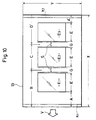
- the function I of the multiple-exposure control device 22 Based on the inputted data, the function I of the multiple-exposure control device 22 performs calculations to find the value A′ of the non-image area on the trailing edge side for defining a layout of the exposed images E1 through E3 on the photosensitive material 13 as shown in Fig. 10, and the data b, c, and d′ for use in reciprocating the original holder 10 as illustrated in Figs.
- A A′
- widths x1 and x2 are provided on the non-image areas A and A′, respectively, which are required to mount the photosensitive material 13 around the plate cylinder 100 in connecting both the leading and trailing edges of the material 13. In this case, since the widths x1 and x2 are provided, the following equations are established: A ⁇ x1 (x1 > 0) A′ ⁇ X2 (X2 > 0)
- condition x2 ⁇ S i.e., A′ ⁇ S is required dependent on exposed image-formation state of the photosensitive material 13, or the like.
- the width x2 > 0, by way of example.
- step S1 to the multiple-exposure data setting device 21 are input the width A of the non-image area on the leading edge side of the photosensitive material 13, the length X of the photosensitive material 13, the length e of the original 12, the number n of exposures of the same, the gap G to be defined among the respective exposed images, and the magnification ratio m.
- the operator's inputting work of these data can be effectively omitted.
- the required number n of the exposures is fixed as in the case of a double-exposure dedicated copying camera, the number being 2, that fixed number n should be automatically inputted to the device 21.
- the data a, A′, a1, and b, c, and d′ are all calculated by the driving data calculating member I on the basis of the above inputted data.
- the original disposal data a is displayed by the display 28.
- the operator mounts the original 12 on the original holder 10 according to the displayed data a and then pushes a start key on the operation panel 27.
- step S5 it is judged by the member J whether the n-1th exposure has been made on the photosensitive material 13. Where that exposure is not terminated, the multiple-exposures of the original 12 onto the photosensitive material 13 are successively performed at step S6, whereas the operation proceeds to step S7 when the n-1 th exposure is completed.
- step S6 the illumination lamp 33 is lighted in synchronization with the commencement of the advancing in the direction H of the original holder 10.
- the rolled photosensitive material 13 is pulled out by the rollers 19.
- the original holder 10, after advancing the distance b, is stopped, per Fig. 11B, and in synchronization with this the photosensitive material 13 is stopped after conveyed the length B.
- the holder 10 is restored the distance c, and stopped to stand by a second exposure, per Fig. 11C.
- the original holder 10 again advances the distance c, and at the same time the photosensitive material 13 is conveyed the distance C and then stopped. Subsequently, the original holder 10 is again returned the distance c to stand by a third exposure.
- step S6 the rollers 36 is not actuated to feed the photosensitive material 13, sandwiching the leading edge thereof, as illustrated in Fig. 7C.
- step S7 the rollers 36 is actuated to feed the photosensitive material 13 into the developing device 20, and at the same time a third (final) exposure is conducted.
- the original holder 10 proceeds the distance d′, per Fig. 11D, and the photosensitive material 13 is synchronously conveyed the length D′ and stopped.
- the length D′ is determined to be unequal to the one B for the first exposure, unlike the first embodiment.
- the exposed photosensitive material 13 is cut by the cutter 39 by the preset length X, per Fig. 7D.
- the original holder 10 is restored to the initial start position shown in Fig. 11A, and stopped.
- the plural exposed images E1 through E3 are made on one sheet of photosensitive material 13 of the above preset size, as illustrated in Fig. 10.
- the multiple-exposure data are preset the length X of the photosensitive material 13, the length e of the original 12, the number n of the exposures, the width A of the photosensitive material 13, the gap G, and the magnification ratio m.
- the value A′ for defining one of the non-image formation length in the direction V may be replaced for one of the value A, the number n and the gap G as input data. This is because, once any three data out of the four data the number n, gap G, and the lengths A, A′ are preset, the rest can be found according to equation (5). Where the present invention is applied to the full scale dedicated copying camera, the magnification scale m is unnecessary to input.
- This embodiment is contemplated in which the invention is applied to the graphic arts copying camera of the full scale, i.e. equal magnification ratio, dedicated type.
- the values b, c, and d for determining the moving amounts of the original holder 10 are set equal to those B, C, and D of the conveying distances for the photosensitive material 13, respectively. Thus, both the holder 10 and the photosensitive material 13 are moved the same amount by the single driving motor 16.
- the first sensor Q0 detects original position P0 of an object to be detected T of the holder 10.
- the second sensor Q1 detects a first position P1 thereof to which the object T of the holder 10 is returned after the first and second exposures and from which the object T advances for the second and third exposures.
- the third sensor Q2 detects a second position P2 to which the object T proceeds for the first and second exposures, and the fourth sensor Q3 a third position P3 which the object T reaches the final exposure.
- the amount b of the holder 1 for the first exposure is defined as a distance which the object T of the holder 10 traverses in moving from the original point P0 to the second position P2, the amount c for the second exposure a distance from the position P1 to position P2, the amount d for the final exposure a distance from the position P1 to the position P3.
- the multiple-exposure operation control device 22 can be brief or concise as compared with that of the first embodiment, and therefore the instant invention can be put into practice more conveniently or advantageously.
- the single motor 16 and change gears 18 are provided for effecting variable magnification recording of the original on the photosensitive material.
- one of the motors preferably the one for the original holder, is designed to be driven at different speeds in accordance with the input magnification ratio.
Landscapes
- Physics & Mathematics (AREA)
- General Physics & Mathematics (AREA)
- Optics & Photonics (AREA)
- Projection-Type Copiers In General (AREA)
- Exposure And Positioning Against Photoresist Photosensitive Materials (AREA)
- Light Sources And Details Of Projection-Printing Devices (AREA)
Description
- The present invention relates to a graphic arts copying machine of a slit-scanning exposure type for use in making intermediate original films, press plates, etc. (see for example US-A-4 674 856) for an offset printing and the like. More particularly, it relates to a so-called multiple-exposure apparatus, incorporated in that machine, for making plural exposed images of the same original onto a photosensitive material such as a master paper for a master plate.
- Generally, when the subject to be printed is reasonably small, the multiple-exposures of an original are made on a single master plate material etc., in which two or more exposures of the same original are made on a photosensitive material for a master plate such as a master paper, and the like. Conventionally, graphic arts copying machines of a type suitable thereof have been employed to effect such multiple-exposures conveniently or advantageously.
- In this connection, U. S. Patent Application Serial No. 059,260 (see the parallel application published as JP-A-62-287255) discloses such multiple-exposure system.
- Heretofore, however, no attempt has been made to concretely propose that multiple-exposure apparatus in a graphic arts copying machine of a slit-exposure type in which the multiple-exposures of the original can automatically be made on the photosensitive material once the required data are input to the data setting means.
- With a view to solving the aforementioned problem, it is an objective of the invention to provide a novel and improved multiple-exposure apparatus in a graphic arts copying machine of a slit-exposure type, in which the multiple-exposures of the original can automatically be made on the photosensitive material once the required data are input to the data setting means.
- To accomplish the above objective, there is provided according to the invention, a multiple-exposure apparatus in a graphic arts copying machine of a slit-exposure type comprising: original holding means capable of horizontally reciprocating; an exposure optical system for exposing an optical image of slitwise segment of said original onto a photosensitive material; moving means for reciprocating said holding means and conveying said photosensitive material relative to said exposure optical system, said moving means adapted to synchronize advancing of said original holding means and said conveying of said photosensitive material; data setting means for setting predetermined data for a predetermined multiple-exposure layout mode of said original on said photosensitive material; means for controlling enabling and disabling of said exposing by said optical system, and said synchronizing by said moving means in an associated relation on the basis of said set data; whereby said multiple-exposures of said original are made on said photosensitive material in said predetermined multiple-exposure layout mode.
- Thus, according to the invention, the multiple-exposures of the original can automatically be made on the photosensitive material once the required data are input to the data setting means. Therefore, simplification in the operation of the copying camera can be effected.
- Furthermore, the multiple-exposures in the desired exposure layout or assignment can be automatically attained.
- Preferably, said predetermined multiple-exposure mode comprises a one in which multiple-exposures of said original are made on said photosensitive material symmetrically relative to the center of a length in a reference direction of said photosensitive material.
- In a preferred embodiment, said predetermined data comprises at least said length of said photosensitive material in said reference direction, a length of said original in a prescribed direction, and any two of a number of said multiple-exposures of said original, a gap between said multiple-exposures in said reference direction, and a length of a non-image formation area of said photosensitive material in said reference direction at one edge side thereof.
- Hence, since the multiple-exposures of said original are made on said photosensitive material symmetrically relative to the center of a length in a reference direction of said photosensitive material according to the preferred embodiment of the invention, uniform printing pressure can be attained by simply mounting the photosensitive material around the plate cylinder of, for example, the offset press machine.
- Preferably, said predetermined multiple-exposure mode comprises a one in which multiple-exposures of said original are made on said photosensitive material asymmetrically relative to the center of a length in a reference direction of said photosensitive material.
- In another preferred embodiment, said predetermined data comprises at least said length of said photosensitive material in said reference direction, a length of said original in a prescribed direction, and any three of a number of said multiple-exposures of said original, a gap between said multiple-exposures in said reference direction, and lengths of non-image formation areas of said photosensitive material in said reference direction at both edge sides thereof.
- In still another preferred embodiment, said exposure optical system is of a full scale type.
- In a yet preferred embodiment, said moving means comprises a single drive motor adapted to rotate, stop, and reversely rotate; rollers for conveying said photosensitive material; a drive transmission member associated with said drive motor and said rollers; and means, connected with said rollers, for enabling a drive transmission of said drive motor via said drive transmission member to said rollers when said original holding means advances and for disabling the same when said original holding means returns.
- Preferably, said exposure optical system is of a variable magnification scale type.
- In a further preferred embodiment, said moving means comprises a single drive motor adapted to rotate, stop, and reversely rotate; rollers for conveying said photosensitive material; a drive transmission member associated with said drive motor and said rollers; means, connected with said rollers, for enabling a drive transmission of said drive motor via said drive transmission member to said rollers when said original holding means advances and for disabling the same when said original holding means returns; and change gears, adapted to be switched in accordance with a drive ratio corresponding to a magnification scale; whereby said photosensitive material is conveyed a distance corresponding in scale change relation to an advancing distance of said original holding means.
- Preferably, said drive transmission member is an endless belt.
- Still preferably, said means for enabling and disabling said drive transmission comprises a one-way clutch member.
- Yet preferably, said moving means comprises rollers for conveying said photosensitive material; and respective drive motors for reciprocating said original holding means and rotating said rollers, one of said drive motors adapted to be driven at different speeds in accordance with a magnification ratio.
- Preferably, said controlling means comprises means for calculating data for use in said reciprocating of said original holding means and said conveying of said photosensitive material on the basis of said set data.
- Still preferably, said data for use in reciprocating of said original holding means and said conveying of said photosensitive material comprises a data for initially mounting said original on said original holder.
- Yet preferably, said data for initially mounting said original on said original holder is a distance from an exposure start line of said original holder to an exposure start line of said original.
- In a preferred embodiment, the apparatus according to the invention further comprises display means for displaying said data for initially mounting said original on said original holder.
- Hence, according to the preferred embodiment of the invention, the operator is able to readily mount the original on the original holding means, simply viewing the displayed data.
- Preferably, said controlling means comprises means for lighting and extinguishing a lamp of said exposure optical system, said lighting and extinguishing means being adapted to light said lamp only for respective time periods required for said original holder means to traverse advancing distances.
- In another embodiment, the apparatus according to the invention further comprises cutter means for cutting said photosensitive material by said length in said reference direction on the basis of said set data.
- Preferably, said photosensitive material is a master paper for a master plate for use in offset printing.
- For the purpose of illustrating the invention, there are shown in the drawing several forms which are presently preferred, it being understood, however, that the invention is not limited to the precise arrangements and instrumentalities shown.
- Fig. 1 is a schematic view illustrating an embodiment of a multiple-exposure apparatus according to the invention;
- Fig. 2 is a schematic view depicting a slit-scanning exposure type copying camera which incorporates each of the apparatuses according to embodiments of the invention;
- Fig. 3 is a schematic view showing a mode in which a sheet of exposed photosensitive material is mounted around a plate cylinder of an offset press machine such that a reference direction of the material agrees with the axial direction of the cylinder;
- Fig. 4 is an explanatory view illustrating an example of a layout or assignment of multiple-exposures according to a first embodiment of the invention;
- Fig. 5A through 5D are explanatory views depicting a mode in which the original holder is driven to reciprocate for enabling a multiple-exposure of the original;
- Figs. 6A and 6B are flowcharts showing the procedure of a multiple-exposure operation;
- Figs. 7A through 7D are explanatory views illustrating a mode in which the photosensitive material is conveyed;
- Fig. 8 is an explanatory view showing a variant of the layout of assignment of the multiple-exposure;
- Fig. 9 is a schematic view illustrating another mode, in which a sheet of exposed photosensitive material is mounted around the plate cylinder such that the reference direction of the material accords with the circumferential direction of the cylinder;
- Fig. 10 is a schematic top plan view depicting an example of the multiple-exposure layout conducted by the multiple-exposure apparatus according to another embodiment of the invention;
- Figs.11A through 11D are views explaining another mode in which the original holder is driven to reciprocate for enabling the multiple-exposure layout of Fig. 10.
- Referring to the drawings, there are described preferred embodiments of the invention below.
- In a graphic arts slit-exposure copying camera to which is applied the apparatus of the present embodiment, an
original holder 10 is provided, capable of horizontally riciprocatory motion and firmly holding an original 12. Beneath theholder 10 is disposed a variable magnificationscale exposure optics 14 for focusing an optical image of slitwise segment of an original 12 onto aphotosensitive material 13. Such variable magnification scale exposure optics is constituted in the manner conventionally known to the graphic arts copying machine art such as that disclosed in U.S. Patent Application No.241,627 (see US-A-4 926 213). Precisely, Theoptics 14 includes an originalilluminating lamp 33,plural lens 50 for determing a light path,image forming lens 51, a set of slit plates 52 for enabling adjustment of width of slit S, etc.. Theimage forming lens 51 and thelight path lens 50 are independently moved by separate driving members (not shown) in accordance with an input magnification scale. Adrive 15, which includes asingle motor 16 and changegears 18, permits theholder 10 andphotosensitive material 13 to move in synchronism with each other. A developingprocessing device 20 is provided to develop and stabilize thephotosensitive material 13 already undergone exposure treatment. Thus, slitwise image segments of the original 12 are successively exposed onto thephotosensitive material 13 through theoptics 14 while the original holder 1 and thephotosensitive material 13 are moved in synchronizm with each other. The exposedphotosensitive material 13 is then treated with developing processing by the developingprocessing device 20. - The size of the
photosensitive material 13 depends on the size of aplate cylinder 100 of an offset press machine being employed where thephotosensitive material 13 being treated is a printing plate material such as a master paper for a master plate. Precisely, the size of themaster paper 13 naturally follows the specified axial and circumferential lengths of the plate cylinder. It is desirable that multiple-exposures of the original 12 be made onto the master paper within an area of such size regularly. - Furthermore, when the photosensitive material is mounted around the plate cylinder of the offset press machine, it is desirable that the plural exposed images so made on the photosensitive material be positioned as closely to the axial center of the cylinder as possible. Namely, exposure layout or assignment of the images on the photosensitive material is preferred to be centered on the axial center of the cylinder. The purpose of this is at precluding that adverse effect in printing quality which is caused by the circumstance that printing pressure by the plate cylinder surface against a surface of an object to be printed is different in axial surface points of the cylinder, particularly between the central and end surface points thereof. Hence such layout is usually conducted with reference to the axial center of the cylinder in order to obtain optimum uniformity in the printing pressure.
- The present embodiment is particularly contemplated in which the
photosensitive material 13 is mounted around theplate cylinder 100 such that the reference direction V of thephotosensitive material 13, i.e., the direction in which plural images are to be exposed thereon in order, agrees with the axial direction of theplate cylinder 100, per Fig. 3. The plural images are accordingly exposed on thephotosensitive material 13 symmetrically with respect to the center of the material 13 in the reference direction V. - The multiple-exposure apparatus according to the invention is incorporated in the aforementioned copying camera, and includes multiple-exposure
data inputting device 21 and multiple-exposureoperation control device 22. - The
data inputting device 21 is provided on anoperation panel 27 of the body of the copying camera. An operator inputs to the device by means of ten-key or the like such data as length X in a feeding direction, i.e., the reference direction V, of thephotosensitive material 13, length e in a reciprocating direction of the original 12, number n of exposures of the original 12 to be made on thephotosensitive material 13, gap G defined among the exposed images of the original 12 on thematerial 13 in that feeding direction, magnification ratio m, etc.. - The multiple-exposure
operation control device 22 performs controls over reciprocating of theoriginal holder 10, conveying of thephotosensitive material 13, and synchronized exposing of the same by the focusingoptics 14 in all associated manner. Thedevice 22 is constituted by a so-called microcomputer including central processing unit (CPU) 23, a read only memory (ROM) 24, and a random access memory (RAM)25. Input and output interface is shown at 26. Thedevice 22 is provided with functions I, J, K, L, and M. For the convenience of explanation, these functions are symbolically illustrated as members incorporated in themicrocomputer 22. - The function I is a driving data calculation member, the duty of which is to find values A, A′ for defining a layout of exposed images E1 through E3 on the
photosensitive material 13 in Fig. 4, a value a for positioning the original 12 on theholder 10, and data b, c, and d for use in reciprocating theholder 10 etc., as detailed below. - In this embodiment, the
photosensitive material 13 is fed in a direction indicated at V in Fig. 4. Width Y of thematerial 13 corresponds to prescribed circumferential length of the plate cylinder of the offset press machine, although the value Y is larger than the latter's by those lengths y1 and y2 which are required to mount thematerial 13 around the cylinder by connecting them with each other. Meanwhile, length X in the feeding direction V of thephotosensitive material 13 corresponds to prescribed axial length of the plate cylinder. Thus, these lengths X and Y of thephotosensitive material 13 are naturally determined by the axial and circumferential lengths of the plate cylinder which are prescribed by a specification of the press machine being employed. - The values A and A′ denote widths of non-image areas at leading and trailing edge sides of the
photosensitive material 13, respectively, wherein the values A and A′ are equal since the images E1 through E3 are made on the material symmetrically with respect the center of the length X in the present embodiment. Each width in the feeding direction of image-formation areas E1 through E3 on thematerial 13 as indicated at E. The width E is m times the length e of the original 12, since the copying camera is of the variable magnification scale type. In case letters or pictures of the original 12 should occupy its whole area, i. e., no blank is laid thereon and accordingly exposed letters or pictures should occupy all of the image-formation areas E1 through E3, the width G is determined to be equal to or larger than slit-exposure width S of the copying camera. This is because adjacent or adjoining portions of the image-formation areas are exposed to the light diffracting from the exposure slit to thereby cancel part of the expected images or at least adversely affect the same if the gap G is smaller than the slit width, or all the more if no gap is provided. Accordingly, the width A, A′ is found based on the following equation:
where n is a number of multiple-exposures of the original, and G = S. - The
original holder 10 advances in a direction denoted at H in Fig. 5A. The original 12 is mounted on theholder 10 such that its exposure startedge line 12a is remote from exposure startline 10a of theholder 10 at distance a. - The distance a is calculated by dividing the thus found value A by the magnification ratio m, and is displayed by a
display 28 on theoperation panel 27. The distance a corresponds to the distance A, since the present invention is applied to the copying camera of the variable magnification type in this embodiment and at the same time theoriginal holder 10 andphotosensitive material 13 are permitted to advance in synchronism with each other by means of a transmissionendless belt 17 which is rotated by thesingle driving motor 16. The operator, viewing the displayed value a, mounts the original 12 onto theholder 10 in the above distance relation. - The function I finds data b to d for driving the
original holder 10 to reciprocate as shown in Fig. 5A through 5D, according to the following equations:


where e is a length of the original 12 in a moving direction H of theholder 10, and corresponds to the width E of the image-formation area E1 through E3 of Fig. 4, whereas g is a value corresponding to the gap G defined among the images E1 to E3 so that gm = G. - According to equation (2), is found an advancing distance b of the
original holder 10 in the direction H for executing a first exposure of the original 12, per Fig. 5B. - Likewise, according to equation (3), is calculated a distance c which the
holder 10 traverses to move backward and forward for another exposure, per Fig. 5C. - According to equation (4), is found a distance d which the
holder 10 advances to effect a final exposure of the original 12, per Fig. 5D. - The data obtained by the function I according to the equation (1) through (4) are stored in its
internal memory RAM 25. - The function J is a synchronous driving control member. The function J is in charge of the control over the driving of the
motor 16 on the basis of the data obtained above by actuating amotor driving circuitry 31. The member J performs the controls of rotating, reversely rotating, and stopping themotor 16 while judging the moving amount of theholder 10 on the basis of pulse signals yielded bypulse generator 16a which is interlockingly connected with themotor 16. -
Conveyer rollers 19 for conveying thephotosensitive material 13 past an exposure station F to feedingrollers 36 are rotated by theendless belt 17 and the change gears 18 via a one-way clutch 19a. The clutch 19a is designed to connect the drive of theconveyor belt 17 and therollers 19 when themotor 16 is rotated whereas to disconnect the same when themotor 16 is reversely rotated. Thus, thephotosensitive material 13 is conveyed in synchronization with the advancing of theoriginal holder 10 whereas kept stationary when theoriginal holder 10 is moved backward. The rolledphotosensitive material 13 is intermittently pulled out and conveyed the lengths B,C, and D, per Fig.4. These lengths B, C, and D are determined to be equal to ones m times the advancing distances b, c, and d of theoriginal holder 10, respectively, which is enabled by the change gears 18 that are switched in accordance with the reduction ratio corresponding to the input magnification scale m by the commands applied by the member J. Naturally, nochange gear 18 is necessary to provide where the copying camera is of a full scale dedicated type. - The function K is an exposure operation commencement and termination control member. The member K fulfills the duty to adjust the
optical system 14 in accordance with the input magnification scale and to control the lighting and extinguishing of anillumination lamp 33 by giving commands to a lightsource actuating circuitry 32 upon receipt the control signals transmitted by the member J. The member K allows thelamp 33 to be lighted for respective time periods required for theoriginal holder 10 to traverse the proceeding distances b, c, and d, so that the same images E1 to E3 of the original 12 are multiple-exposed on thephotosensitive material 13 through the focusingoptics 14. - The function L is a feeding rollers controlling member. The function of the device L is to control the driving of a
motor 35 by applying commands to feedingrollers actuating circuitry 34 upon receiving the control signals delivered from the member J. Thus, under the control of the member L, the feedingrollers 36 sandwiches the leading edge of thephotosensitive material 13 undergone a first exposure and being carried by theconveyor rollers 19. Then, therollers 36 stands by, as doing so, until an n-1th exposure is completed. No sooner does commence the final exposure than therollers 36 begins to feed thephotosensitive material 13 into the developingdevice 20. - The function M is a cutter control member whose duty is to control the driving of a
motor 38 for acutter 39 by giving commands to acutter actuating circuitry 37 upon receipt of the control signals applied by the control member J. Under the control of the member M, thecutter 39 is actuated by the drivingmotor 38 to traverse and cut the stationaryphotosensitive material 13 undergone the final exposure, by the input length X. - Description is hereinbelow made as to procedures of the multiple-exposure operation per Fig. 6A and 6B.
- At step S1, to the multiple-exposure
data setting device 21 are input the length X of thephotosensitive material 13, the length e of the original 12, the number n of exposures of the same, the gap G to be defined among the respective exposed images, and the magnification ratio m. - Where that preset value as the gap G is arranged to be automatically input to the
device 21 which is equal to or larger than the slit width S of the copying camera, the operator's inputting work of the gap data G can be effectively omitted. At the same time it is ensured that the exposed images can be concentrated on the center in the reference direction V of thephotosensitive material 13 to the utmost. - Where the required number n of the exposures is fixed as in the case of a double-exposure dedicated copying camera, the number being 2, that fixed number n should be automatically inputted to the
device 21. - At step S2, the data A, a, and b, c, and d are all calculated by the driving data calculating member I on the basis of the above inputted data.
- At step S3, the original disposal data a is displayed by the
display 28. At step S4, the operator mounts the original 12 on theoriginal holder 10 according to the displayed data a and then pushes a start key on theoperation panel 27. - At step S5, it is judged by the member J whether the n-1th exposure on the
photosensitive material 13 is completed. Where that exposure is not terminated, the multiple-exposures of the original 12 onto thephotosensitive material 13 are successively performed at step S6, whereas the operation proceeds to step S7 when the n-1 th exposure is completed. - In detail, at step S6 the
illumination lamp 33 is lighted in synchronization with the commencement of the advancing in the direction H of theoriginal holder 10. At the same time, the rolledphotosensitive material 13 is pulled out by therollers 19. However, it is not until the leading edge of thephotosensitive material 13 is conveyed the length A that the first image E1 starts being exposed and recorded thereon, as readily appreciated from Fig. 7B. Theoriginal holder 10, after advancing the distance b, is stopped, per Fig. 5B, and in synchronization with this thephotosensitive material 13 is stopped after conveyed the length B. Next, theholder 10 is restored the distance c, and stopped to stand by a second exposure, per Fig. 5C. - To effect the second exposure, the
original holder 10 again advances the distance c, and at the same time thephotosensitive material 13 is conveyed the distance C and then stopped. Subsequently, theoriginal holder 10 is again returned the distance c to stand by a third exposure. - During step S6, the
rollers 26 is not actuated to feed thephotosensitive material 13, sandwiching the leading edge thereof, as illustrated in Fig. 7C. - At step S7, the
rollers 36 is actuated to feed thephotosensitive material 13 into the developingdevice 20, and at the same time a third (final) exposure is conducted. To attain the final exposure, step S8, theoriginal holder 10 proceeds the distance d, per Fig. 4D, and thephotosensitive material 13 is synchronously conveyed the length D and stopped. The length D is determined to be equal to the one B for the first exposure. - At step S9, the exposed
photosensitive material 13 is cut by thecutter 39 by the present length X, per Fig. 7D. Theoriginal holder 10 is restored to the initial start position shown in Fig. 5A, and stopped. In consequence, the plural exposed images E1 through E3 are made on one sheet ofphotosensitive material 13 of the above preset size such that the exposed assignment or layout thereof is symmetrical with respect to the center of the length X of thephotosensitive material 13. - In this embodiment, as the multiple-exposure data are preset the length X of the
photosensitive material 13, the length e of the original 12, the number n of the exposures, the gap G, and the magnification ratio m. The value A (A′) for defining the non-image formation length in the direction X, however, may be replaced for one of the number n and the gap G as input data. This is because, once any two data out of the three data the number n, gap G, and the length A are preset, the other can be found according to equation (1). Where the present invention is applied to the full scale dedicated copying camera, the magnification scale m is unneccessay to input. - In this embodiment, the width G is determined to be equal to or larger than the slit exposure width S of the reason above. However, insofar as a blank = S/2m is laid on the original 10 and accordingly exposed letters or pictures should occupy each of the image-formation areas E1 through E3 with a blank m times the former, no gap G is necessary to provide, as depicted in Fig. 8. In order to effect the exposure mode of Fig. 8, the above driving data etc. are found based on G = 0 in equations (1) through (4).
- The present embodiment is contemplated in which the
photosensitive material 13 is mounted around theplate cylinder 100 such that the reference direction V of thephotosensitive material 13, i.e., the direction in which plural images are to be exposed thereon in order, agrees with the circumferential direction of theplate cylinder 100, per Fig. 9. Accordingly, it is unnecessary to expose the plural images on thephotosensitive material 13 symmetrically with respect to the center of the material 13 in the reference direction V. To attain the uniform printing pressure at issue, the operator simply accords the center in a direction normal to the direction V of thephotosensitive material 13, with the axial center of theplate cylinder 100, in mounting the former around the latter. - Differences of the second embodiment from the first embodiment are described below.
- In this embodiment, the operator inputs to the
data inputting device 21 by means of ten-key or the like such data as the length X of thephotosensitive material 13, the length e of the original 10, the number n of the exposures, the width A of the non-image area at leading edge side of thephotosensitive material 13, the gap G, and the magnification scale m. - Based on the inputted data, the function I of the multiple-
exposure control device 22 performs calculations to find the value A′ of the non-image area on the trailing edge side for defining a layout of the exposed images E1 through E3 on thephotosensitive material 13 as shown in Fig. 10, and the data b, c, and d′ for use in reciprocating theoriginal holder 10 as illustrated in Figs. 11A through 11D, according to the above equations (2) and (3) and further to the following equations:

where A = A′, and a1 is a value obtained by dividing the width A′ by the magnification scale m (a1m = A′). Per Fig. 10, widths x1 and x2 are provided on the non-image areas A and A′, respectively, which are required to mount thephotosensitive material 13 around theplate cylinder 100 in connecting both the leading and trailing edges of thematerial 13. In this case, since the widths x1 and x2 are provided, the following equations are established:

- Such width x2, however, is not always necessary depending upon the type of the plate cylinder, so that x2 = 0, i.e., A′= 0 if unnecessary. Furthermore, condition x2 ≧ S, i.e., A′ ≧ S is required dependent on exposed image-formation state of the
photosensitive material 13, or the like. In this embodiment, explanation is made as to the case where the width x2 > 0, by way of example. Needless to say, the required data can be found according to the above equations on condition A′ = 0. - Description is herebelow made as to procedures of the multiple-exposure operation according to the present embodiment per Fig. 6A and 6B, like the first embodiment.
- At step S1, to the multiple-exposure
data setting device 21 are input the width A of the non-image area on the leading edge side of thephotosensitive material 13, the length X of thephotosensitive material 13, the length e of the original 12, the number n of exposures of the same, the gap G to be defined among the respective exposed images, and the magnification ratio m. - Where the values A and G as fixed are arranged to be automatically input to the
device 21, the operator's inputting work of these data can be effectively omitted. Where the required number n of the exposures is fixed as in the case of a double-exposure dedicated copying camera, the number being 2, that fixed number n should be automatically inputted to thedevice 21. - At step S2, the data a, A′, a1, and b, c, and d′ are all calculated by the driving data calculating member I on the basis of the above inputted data.
- At step S3, the original disposal data a is displayed by the
display 28. At step S4, the operator mounts the original 12 on theoriginal holder 10 according to the displayed data a and then pushes a start key on theoperation panel 27. - At step S5, it is judged by the member J whether the n-1th exposure has been made on the
photosensitive material 13. Where that exposure is not terminated, the multiple-exposures of the original 12 onto thephotosensitive material 13 are successively performed at step S6, whereas the operation proceeds to step S7 when the n-1 th exposure is completed. - In detail, at step S6 the
illumination lamp 33 is lighted in synchronization with the commencement of the advancing in the direction H of theoriginal holder 10. At the same time, the rolledphotosensitive material 13 is pulled out by therollers 19. However, it is not until the leading edge of thephotosensitive material 13 is conveyed the length A that the first image E1 starts being exposed and recorded thereon, as readily appreciated from Fig. 7B. Theoriginal holder 10, after advancing the distance b, is stopped, per Fig. 11B, and in synchronization with this thephotosensitive material 13 is stopped after conveyed the length B. Next, theholder 10 is restored the distance c, and stopped to stand by a second exposure, per Fig. 11C. - To effect the second exposure, the
original holder 10 again advances the distance c, and at the same time thephotosensitive material 13 is conveyed the distance C and then stopped. Subsequently, theoriginal holder 10 is again returned the distance c to stand by a third exposure. - During step S6, the
rollers 36 is not actuated to feed thephotosensitive material 13, sandwiching the leading edge thereof, as illustrated in Fig. 7C. - At step S7, the
rollers 36 is actuated to feed thephotosensitive material 13 into the developingdevice 20, and at the same time a third (final) exposure is conducted. To attain the final exposure, theoriginal holder 10 proceeds the distance d′, per Fig. 11D, and thephotosensitive material 13 is synchronously conveyed the length D′ and stopped. The length D′ is determined to be unequal to the one B for the first exposure, unlike the first embodiment. - At step S9, the exposed
photosensitive material 13 is cut by thecutter 39 by the preset length X, per Fig. 7D. Theoriginal holder 10 is restored to the initial start position shown in Fig. 11A, and stopped. In consequence, the plural exposed images E1 through E3 are made on one sheet ofphotosensitive material 13 of the above preset size, as illustrated in Fig. 10. - In this embodiment, as the multiple-exposure data are preset the length X of the
photosensitive material 13, the length e of the original 12, the number n of the exposures, the width A of thephotosensitive material 13, the gap G, and the magnification ratio m. The value A′ for defining one of the non-image formation length in the direction V, however, may be replaced for one of the value A, the number n and the gap G as input data. This is because, once any three data out of the four data the number n, gap G, and the lengths A, A′ are preset, the rest can be found according to equation (5). Where the present invention is applied to the full scale dedicated copying camera, the magnification scale m is unnecessary to input. - This embodiment is contemplated in which the invention is applied to the graphic arts copying camera of the full scale, i.e. equal magnification ratio, dedicated type.
- Differences of the current embodiment from the first embodiment are described below.
- The values b, c, and d for determining the moving amounts of the
original holder 10 are set equal to those B, C, and D of the conveying distances for thephotosensitive material 13, respectively. Thus, both theholder 10 and thephotosensitive material 13 are moved the same amount by thesingle driving motor 16. - To this end, it is possible to replace the
pulse generator 16a with first through fourth sensors Q0 - Q3 for detecting positions of theoriginal holder 10 in order to determine the advancing amounts b, c, and d of theholder 10, per Fig. 2. - The first sensor Q0 detects original position P0 of an object to be detected T of the
holder 10. The second sensor Q1 detects a first position P1 thereof to which the object T of theholder 10 is returned after the first and second exposures and from which the object T advances for the second and third exposures. The third sensor Q2 detects a second position P2 to which the object T proceeds for the first and second exposures, and the fourth sensor Q3 a third position P3 which the object T reaches the final exposure. - The amount b of the holder 1 for the first exposure is defined as a distance which the object T of the
holder 10 traverses in moving from the original point P0 to the second position P2, the amount c for the second exposure a distance from the position P1 to position P2, the amount d for the final exposure a distance from the position P1 to the position P3. - It is possible to slide the positions of the sensors Q2 and Q3 in order to suitably change the same depending on the size e of the original 12.
- Thus, in this embodiment, the multiple-exposure
operation control device 22 can be brief or concise as compared with that of the first embodiment, and therefore the instant invention can be put into practice more conveniently or advantageously. - Furthermore, since the full scale dedicated copying camera is employed, no change gear is necessary to provide. Thus, the simplification of the arrangement can be further promoted in this embodiment.
- In the above embodiments, the
single motor 16 and change gears 18 are provided for effecting variable magnification recording of the original on the photosensitive material. To the same end, however, it is possible to omit the provisions of the gears and the endless belt, and to instead provide discrete driving motors for reciprocating theoriginal holder 10 and rotating the conveying rollers for thephotosensitive material 13. In that case, one of the motors, preferably the one for the original holder, is designed to be driven at different speeds in accordance with the input magnification ratio. - While the preferred embodiments of the present invention have been described above, it should be understood that various modifications may be made herein without departing from the scope of the appended claims.
- The features disclosed in the foregoing description, in the claims and/or in the accompanying drawings may, both separately and in any combination thereof, be material for realising the invention in diverse forms thereof.
Claims (17)
- A multiple-exposure apparatus for a graphic arts copying machine, said apparatus comprising:
original holding means (10) adapted for horizontal reciprocating motion;
an optical exposure system (14) for exposing an optical image of a slitwise segment of said original (12) onto a photosensitive material (13);
moving means (15) for reciprocating said holding means (10) and conveying said photosensitive material (13) relative to said optical exposure system (14), said moving means (15) being adapted to advance said original holding means (10) and to convey said photosensitive material (13) in synchronism,
characterized in
that there are provided data setting means (21) for setting predetermined data for a predetermined multiple-exposure layout mode of said original (12) onto said photosensitive material (13);
that there are provided controlling means (22) for controlling the operation of said optical system (14) and said moving means (15) in an associated relationship as a function of said predetermined data set by said data setting means (21), whereby multiple-exposures of said original are made on said photosensitive material (13) in said predetermined multiple-exposure layout mode;
that said predetermined multiple-exposure mode is one in which multiple-exposures of said original (12) are made onto said photosensitive material (13) symmetrically relative to a center of a length of said photosensitive material (13) along a predefined reference direction (V) of said photosensitive material (13); and in
that said predetermined data comprise at least said length (X) of said photosensitive material (13) in said reference direction, a length of said original (12) in a prescribed direction (Y), and any two of the following three parameters, (1) a number (n) of said multiple-exposures of said original (12), (2) a gap (6) on said photosensitive material (13) between said multiple-exposures in said reference direction (V), and (3) a length of a non-image formation area of said photosensitive material (13) in said reference direction (V) at one side edge thereof. - A multiple-exposure apparatus for a graphic arts copying machine, said apparatus comprising:
original holding means (10) adapted for horizontal reciprocating motion;
an optical exposure system (14) for exposing an optical image of a slitwise segment of said original (12) onto a photosensitive material (13);
moving means (15) for reciprocating said holding means (10) and conveying said photosensitive material (13) relative to said optical exposure system (14), said moving means (15) being adapted to advance said original holding means (10) and to convey said photosensitive material (13) in synchronism,
characterized in
that there are provided data setting means (21) for setting predetermined data for a predetermined multiple-exposure layout mode of said original (12) onto said photosensitive material (13);
that there are provided controlling means (22) for controlling the operation of said optical system (14) and said moving means (15) in an associated relationship as a function of said predetermined data set by said data setting means (21), whereby multiple-exposures of said original are made on said photosensitive material (13) in said predetermined multiple-exposure layout mode;
that said predetermined multiple-exposure mode is one in which multiple-exposures of said original (12) are made onto said photosensitive material (13) asymmetrically relative to a center of a length of said photosensitive material (13) along a predefined reference direction (V) of said photosensitive material (13); and in
that said predetermined data comprise at least said length (X) of said photosensitive material (13) in said reference direction, a length of said original (12) in a prescribed direction (Y), and any three of the following three parameters, (1) a number (n) of said multiple-exposures of said original (12), (2) a gap on said photosensitive material (13) between said multiple-exposures in said reference direction (V), and (3) lengths of a non-image formation areas of said photosensitive material (13) in said reference direction (V) at both side edges thereof. - An apparatus as recited in claim 1 or 2, wherein said exposure optical system (14) is of a full scale type.
- An apparatus as recited in one of the preceding claims, wherein said moving means (15) comprises a single drive motor (16) adapted to rotate, stop, and reversely rotate; rollers (19) for conveying said photosensitive material (13); a drive transmission member (17) associated with said drive motor (16) and said rollers (19); and means (19a), connected with said rollers (19), for enabling a drive transmission of said drive motor (16) via said drive transmission member (17) to said rollers (19) when said original holding means (10) advances and disabling the same when said original holding means (10) returns.
- An apparatus as recited in claim 4, wherein said drive transmission member is an endless belt (17).
- An apparatus as recited in claim 1 or 2, wherein said exposure optical system (14) is of a variable magnification scale type.
- An apparatus as recited in claim 6, wherein said moving means (15) comprises a single drive motor (16) adapted to rotate, stop, and reversely rotate; rollers (19) for conveying said photosensitive material 813); a drive transmission member (17) associated with said drive motor (16) and said rollers (19); and means (19a), connected with said rollers (19), for enabling a drive transmission of said drive motor (16) via said drive transmission member (17) to said rollers (19) when said original holding means (10) advances and disabling the same when said original holding means (10) returns; and change gears (18), adapted to be switched in accordance with a drive ratio corresponding to a magnification scale; whereby said photosensitive material (13) is conveyed through a distance corresponding in scale relation to an advancing distance of said original holding means (10).
- An apparatus as recited in claim 7, wherein said drive transmission member is an endless belt (17).
- An apparatus as recited in claim 7, wherein said means for enabling and disabling said drive transmission comprises a one-way clutch member (19a).
- An apparatus as recited in claim 6, wherein said moving means (15) comprises rollers (19) for conveying said photosensitive material (13); and respective drive motors for reciprocating said original holding means (10) and rotating said rollers (19), one of said drive motors adapted to be driven at different speeds in accordance with a magnification ratio.
- An apparatus as recited in one of the preceding claims, wherein said controlling means (22) comprises means for calculating data for controlling said reciprocating of said original holding means (10) and said conveying of said photosensitive material (13) on the basis of said set data.
- An apparatus as recited in claim 11, wherein said data for use in reciprocating of said original holding means (10) and said conveying of said photosensitive material (13) comprises the datum necessary for initially placing said original (12) on said original holder (10).
- An apparatus as recited in claim 12, wherein said data for initially placing said original (12) on said original holder (10) is a distance from an exposure start line of said original holder (10) to an exposure start line of said original (12).
- An apparatus as recited in claim 13, further comprising display means (28) for displaying said data for initially placing said original (12) on said original holder (10).
- An apparatus as recited in one of the preceding claims, wherein said controlling means (22) comprises means (32) for lighting and extinguishing a lamp (33) of said exposure optical system (14), said lighting and extinguishing means (32) being adapted to light said lamp (33) only for respective time periods required for said original holder means (10) to traverse predefined advancing distances.
- An apparatus as recited in one of the preceding claims, further comprising cutter means (39) for cutting said photosensitive material (13) by said length in said reference direction (V) on the basis of said set predetermined data.
- An apparatus as recited in one of the preceding claims, wherein said photosensitive material (13) is a master paper for a master plate for use in offset printing.
Applications Claiming Priority (2)
| Application Number | Priority Date | Filing Date | Title |
|---|---|---|---|
| JP15668/88 | 1988-01-25 | ||
| JP63015668A JPH0758398B2 (en) | 1988-01-25 | 1988-01-25 | Slit scanning exposure type copying camera |
Publications (3)
| Publication Number | Publication Date |
|---|---|
| EP0326080A2 EP0326080A2 (en) | 1989-08-02 |
| EP0326080A3 EP0326080A3 (en) | 1991-10-02 |
| EP0326080B1 true EP0326080B1 (en) | 1995-03-15 |
Family
ID=11895122
Family Applications (1)
| Application Number | Title | Priority Date | Filing Date |
|---|---|---|---|
| EP89101195A Expired - Lifetime EP0326080B1 (en) | 1988-01-25 | 1989-01-24 | A multiple-exposure apparatus in a graphic arts copying machine of a slit-exposure type |
Country Status (4)
| Country | Link |
|---|---|
| US (1) | US4914473A (en) |
| EP (1) | EP0326080B1 (en) |
| JP (1) | JPH0758398B2 (en) |
| DE (1) | DE68921654T2 (en) |
Families Citing this family (6)
| Publication number | Priority date | Publication date | Assignee | Title |
|---|---|---|---|---|
| JP2508820B2 (en) * | 1988-10-29 | 1996-06-19 | 岩崎通信機株式会社 | Electrophotographic plate making machine |
| JPH0812381B2 (en) * | 1989-12-20 | 1996-02-07 | 大日本スクリーン製造株式会社 | Scanning exposure type camera for multi-sided mounting |
| JPH03191337A (en) * | 1989-12-20 | 1991-08-21 | Dainippon Screen Mfg Co Ltd | Scanning exposing type camera |
| US5274419A (en) * | 1989-12-20 | 1993-12-28 | Dainippon Screen Mfg. Co., Ltd. | Camera and photosensitive material feed unit useful therefor |
| JPH05204120A (en) * | 1991-02-19 | 1993-08-13 | Seiko Epson Corp | Image forming device |
| JP2901777B2 (en) * | 1991-03-28 | 1999-06-07 | 大日本スクリーン製造株式会社 | Scanning exposure equipment |
Citations (2)
| Publication number | Priority date | Publication date | Assignee | Title |
|---|---|---|---|---|
| JPS62287255A (en) * | 1986-06-05 | 1987-12-14 | Dainippon Screen Mfg Co Ltd | Multiplane exposing method for plate making copying machine |
| US4926213A (en) * | 1987-09-11 | 1990-05-15 | Dainippon Screen Mfg. Co., Ltd. | Apparatus for holding sensitized material in slitwise exposure type copying camera |
Family Cites Families (8)
| Publication number | Priority date | Publication date | Assignee | Title |
|---|---|---|---|---|
| US3598489A (en) * | 1969-01-02 | 1971-08-10 | Spaco Inc | Projection system |
| JPS4813446B1 (en) * | 1969-03-10 | 1973-04-27 | ||
| US4076404A (en) * | 1972-04-19 | 1978-02-28 | Canon Kabushiki Kaisha | Method of and apparatus for electronic color photography and photosensitive member used for the same |
| JPS57198469A (en) * | 1981-06-01 | 1982-12-06 | Ricoh Co Ltd | Exposing method for photosensitive element |
| JPS591050A (en) * | 1982-06-26 | 1984-01-06 | Tokyu Kk | Packing device of backup material |
| US4660957A (en) * | 1983-11-25 | 1987-04-28 | Canon Kabushiki Kaisha | Image forming apparatus with two mode original handling system |
| JPS614065A (en) * | 1984-06-19 | 1986-01-09 | Iwatsu Electric Co Ltd | Exposure device of plate making machine |
| JPS61273531A (en) * | 1985-05-29 | 1986-12-03 | Minolta Camera Co Ltd | Image forming device |
-
1988
- 1988-01-25 JP JP63015668A patent/JPH0758398B2/en not_active Expired - Lifetime
-
1989
- 1989-01-24 DE DE68921654T patent/DE68921654T2/en not_active Expired - Fee Related
- 1989-01-24 EP EP89101195A patent/EP0326080B1/en not_active Expired - Lifetime
- 1989-01-24 US US07/300,917 patent/US4914473A/en not_active Expired - Fee Related
Patent Citations (2)
| Publication number | Priority date | Publication date | Assignee | Title |
|---|---|---|---|---|
| JPS62287255A (en) * | 1986-06-05 | 1987-12-14 | Dainippon Screen Mfg Co Ltd | Multiplane exposing method for plate making copying machine |
| US4926213A (en) * | 1987-09-11 | 1990-05-15 | Dainippon Screen Mfg. Co., Ltd. | Apparatus for holding sensitized material in slitwise exposure type copying camera |
Also Published As
| Publication number | Publication date |
|---|---|
| DE68921654T2 (en) | 1995-07-27 |
| JPH0758398B2 (en) | 1995-06-21 |
| JPH01189657A (en) | 1989-07-28 |
| US4914473A (en) | 1990-04-03 |
| EP0326080A2 (en) | 1989-08-02 |
| EP0326080A3 (en) | 1991-10-02 |
| DE68921654D1 (en) | 1995-04-20 |
Similar Documents
| Publication | Publication Date | Title |
|---|---|---|
| DE69736823T2 (en) | Image generation apparatus with amplitude and phase detection of register errors | |
| EP0308967B1 (en) | Photographic printing method and apparatus therefor | |
| DE69314714T2 (en) | Method and device for reading an image | |
| US4468115A (en) | Travelling lamp house for 3-D photographic printer | |
| DE19502567C2 (en) | Imaging device | |
| CA1335162C (en) | Method of controlling variation of density of images in 3-d pictures | |
| EP0326080B1 (en) | A multiple-exposure apparatus in a graphic arts copying machine of a slit-exposure type | |
| US5111236A (en) | Multiple-print 3-D printer and process | |
| US5497217A (en) | Method of copying a photograph by using a copier with border eliminating mode | |
| EP0509170B1 (en) | 3-D camera, preloaded and integrated high-speed printing system | |
| EP0328267B1 (en) | Printer for three dimensional lenticular print material | |
| GB2101344A (en) | Variable magnification photocopying | |
| US4884106A (en) | Multi-image reproduction apparatus | |
| DE69806877T2 (en) | Method and apparatus for positioning a sheet of photosensitive material in a photographic printer | |
| US4641951A (en) | Method and apparatus for electrophotographically reproducing a desired portion of an original on copying paper | |
| JPS61201261A (en) | Controller for feed timing of transfer paper | |
| EP0434058B1 (en) | Camera and photosensitive material feed unit useful therefor | |
| JPS6352381B2 (en) | ||
| JPH1177979A (en) | Image input method and image input device | |
| US4959689A (en) | Electrophotographic plate-making machine with independent motors for moving the copy holder, conveying rollers and focus region rollers | |
| JP2613458B2 (en) | Focus position indexing exposure device for slit scanning exposure type copying camera | |
| JPH01128069A (en) | Trialingly photographed image exposing device for slit scan exposure type copying camera | |
| JPH01217461A (en) | Photographic printing processor | |
| JP2698136B2 (en) | Image forming device | |
| KR830000445B1 (en) | Photo typewriter |
Legal Events
| Date | Code | Title | Description |
|---|---|---|---|
| PUAI | Public reference made under article 153(3) epc to a published international application that has entered the european phase |
Free format text: ORIGINAL CODE: 0009012 |
|
| AK | Designated contracting states |
Kind code of ref document: A2 Designated state(s): DE FR GB |
|
| PUAL | Search report despatched |
Free format text: ORIGINAL CODE: 0009013 |
|
| AK | Designated contracting states |
Kind code of ref document: A3 Designated state(s): DE FR GB |
|
| 17P | Request for examination filed |
Effective date: 19920304 |
|
| 17Q | First examination report despatched |
Effective date: 19930816 |
|
| GRAA | (expected) grant |
Free format text: ORIGINAL CODE: 0009210 |
|
| AK | Designated contracting states |
Kind code of ref document: B1 Designated state(s): DE FR GB |
|
| ET | Fr: translation filed | ||
| REF | Corresponds to: |
Ref document number: 68921654 Country of ref document: DE Date of ref document: 19950420 |
|
| PLBE | No opposition filed within time limit |
Free format text: ORIGINAL CODE: 0009261 |
|
| STAA | Information on the status of an ep patent application or granted ep patent |
Free format text: STATUS: NO OPPOSITION FILED WITHIN TIME LIMIT |
|
| 26N | No opposition filed | ||
| PGFP | Annual fee paid to national office [announced via postgrant information from national office to epo] |
Ref country code: FR Payment date: 19980109 Year of fee payment: 10 |
|
| PGFP | Annual fee paid to national office [announced via postgrant information from national office to epo] |
Ref country code: GB Payment date: 19980115 Year of fee payment: 10 |
|
| PGFP | Annual fee paid to national office [announced via postgrant information from national office to epo] |
Ref country code: DE Payment date: 19980202 Year of fee payment: 10 |
|
| PG25 | Lapsed in a contracting state [announced via postgrant information from national office to epo] |
Ref country code: GB Free format text: LAPSE BECAUSE OF NON-PAYMENT OF DUE FEES Effective date: 19990124 |
|
| GBPC | Gb: european patent ceased through non-payment of renewal fee |
Effective date: 19990124 |
|
| PG25 | Lapsed in a contracting state [announced via postgrant information from national office to epo] |
Ref country code: FR Free format text: LAPSE BECAUSE OF NON-PAYMENT OF DUE FEES Effective date: 19990930 |
|
| PG25 | Lapsed in a contracting state [announced via postgrant information from national office to epo] |
Ref country code: DE Free format text: LAPSE BECAUSE OF NON-PAYMENT OF DUE FEES Effective date: 19991103 |
|
| REG | Reference to a national code |
Ref country code: FR Ref legal event code: ST |