EP0326045A2 - A field spraying device - Google Patents
A field spraying device Download PDFInfo
- Publication number
- EP0326045A2 EP0326045A2 EP89101021A EP89101021A EP0326045A2 EP 0326045 A2 EP0326045 A2 EP 0326045A2 EP 89101021 A EP89101021 A EP 89101021A EP 89101021 A EP89101021 A EP 89101021A EP 0326045 A2 EP0326045 A2 EP 0326045A2
- Authority
- EP
- European Patent Office
- Prior art keywords
- hose
- spraying device
- spray
- nozzles
- manner
- Prior art date
- Legal status (The legal status is an assumption and is not a legal conclusion. Google has not performed a legal analysis and makes no representation as to the accuracy of the status listed.)
- Granted
Links
- 238000005507 spraying Methods 0.000 title claims abstract description 28
- 239000007921 spray Substances 0.000 claims abstract description 12
- 239000012858 resilient material Substances 0.000 claims abstract description 3
- 239000004033 plastic Substances 0.000 claims description 4
- 229920003023 plastic Polymers 0.000 claims description 4
- 230000000717 retained effect Effects 0.000 claims description 3
- 239000007788 liquid Substances 0.000 abstract description 18
- 239000000463 material Substances 0.000 abstract description 7
- 230000000694 effects Effects 0.000 abstract description 3
- 241000196324 Embryophyta Species 0.000 description 6
- 238000007599 discharging Methods 0.000 description 5
- 239000004698 Polyethylene Substances 0.000 description 2
- -1 polyethylene Polymers 0.000 description 2
- 229920000573 polyethylene Polymers 0.000 description 2
- 230000008093 supporting effect Effects 0.000 description 2
- 108091006146 Channels Proteins 0.000 description 1
- 241001052209 Cylinder Species 0.000 description 1
- 229920004934 Dacron® Polymers 0.000 description 1
- 229910000831 Steel Inorganic materials 0.000 description 1
- 238000005452 bending Methods 0.000 description 1
- 208000018747 cerebellar ataxia with neuropathy and bilateral vestibular areflexia syndrome Diseases 0.000 description 1
- 238000000151 deposition Methods 0.000 description 1
- 239000000203 mixture Substances 0.000 description 1
- 229920000728 polyester Polymers 0.000 description 1
- 239000005020 polyethylene terephthalate Substances 0.000 description 1
- 230000035939 shock Effects 0.000 description 1
- 239000010959 steel Substances 0.000 description 1
- 238000003756 stirring Methods 0.000 description 1
- 239000000725 suspension Substances 0.000 description 1
- 238000009827 uniform distribution Methods 0.000 description 1
Images
Classifications
-
- A—HUMAN NECESSITIES
- A01—AGRICULTURE; FORESTRY; ANIMAL HUSBANDRY; HUNTING; TRAPPING; FISHING
- A01B—SOIL WORKING IN AGRICULTURE OR FORESTRY; PARTS, DETAILS, OR ACCESSORIES OF AGRICULTURAL MACHINES OR IMPLEMENTS, IN GENERAL
- A01B59/00—Devices specially adapted for connection between animals or tractors and agricultural machines or implements
- A01B59/06—Devices specially adapted for connection between animals or tractors and agricultural machines or implements for machines mounted on tractors
- A01B59/061—Devices specially adapted for connection between animals or tractors and agricultural machines or implements for machines mounted on tractors specially adapted for enabling connection or disconnection controlled from the driver's seat
- A01B59/062—Devices specially adapted for connection between animals or tractors and agricultural machines or implements for machines mounted on tractors specially adapted for enabling connection or disconnection controlled from the driver's seat the connection comprising a rigid interface frame on the tractor
-
- A—HUMAN NECESSITIES
- A01—AGRICULTURE; FORESTRY; ANIMAL HUSBANDRY; HUNTING; TRAPPING; FISHING
- A01M—CATCHING, TRAPPING OR SCARING OF ANIMALS; APPARATUS FOR THE DESTRUCTION OF NOXIOUS ANIMALS OR NOXIOUS PLANTS
- A01M7/00—Special adaptations or arrangements of liquid-spraying apparatus for purposes covered by this subclass
- A01M7/0003—Atomisers or mist blowers
- A01M7/0014—Field atomisers, e.g. orchard atomisers, self-propelled, drawn or tractor-mounted
-
- A—HUMAN NECESSITIES
- A01—AGRICULTURE; FORESTRY; ANIMAL HUSBANDRY; HUNTING; TRAPPING; FISHING
- A01M—CATCHING, TRAPPING OR SCARING OF ANIMALS; APPARATUS FOR THE DESTRUCTION OF NOXIOUS ANIMALS OR NOXIOUS PLANTS
- A01M7/00—Special adaptations or arrangements of liquid-spraying apparatus for purposes covered by this subclass
- A01M7/005—Special arrangements or adaptations of the spraying or distributing parts, e.g. adaptations or mounting of the spray booms, mounting of the nozzles, protection shields
- A01M7/006—Mounting of the nozzles
-
- A—HUMAN NECESSITIES
- A01—AGRICULTURE; FORESTRY; ANIMAL HUSBANDRY; HUNTING; TRAPPING; FISHING
- A01M—CATCHING, TRAPPING OR SCARING OF ANIMALS; APPARATUS FOR THE DESTRUCTION OF NOXIOUS ANIMALS OR NOXIOUS PLANTS
- A01M7/00—Special adaptations or arrangements of liquid-spraying apparatus for purposes covered by this subclass
- A01M7/005—Special arrangements or adaptations of the spraying or distributing parts, e.g. adaptations or mounting of the spray booms, mounting of the nozzles, protection shields
- A01M7/0064—Protection shields
Definitions
- the invention relates to a spraying device comprisising an elongated spray beam with a plurality of spray nozzles.
- the known spray beams are encumbered with the drawback that they must be situated relatively far from the crop so as to achieve a substantially uniform discharging of the spraying material. A consequence thereof is an increased risk of undesired wind movement.
- a spraying device of the above type is according to the invention characterized by comprising an at least partially inflatable hose connectable to a compressed-air source, said hose comprising one or more slotted discharge openings extending in the longitudinal direction of the hose.
- the slotted discharge opening(s) may be pivotally mounted by utilizing the feature that the hose is made of a resilient material.
- the invention utilizes the feature that the resilient top portion allows a turning movement in such a manner that the discharging direction can be adjusted. Addition strictlyally, it is possible to take the wind velocity, the velocity of the vehicle etc. into account. In other words it is possible to improve the horrtion of the sprayed materials simultaneously with taking optimum care of the crop.
- the spraying is more or less sensitive to wind, especially when small nozzles and high pressures are involved.
- large nozzles or low pressures are recommended in connection with sprayings where the surrounding wind is higher than 4-6 m/sec because the drop size is thereby increased.
- the latter is substantially caused by large drops possessing a higher energy than small drops.
- the large drops have a substantially better chance of coming into contact with the article to be sprayed.
- the air-liquid system has the effect that even the small wind-sensitive drops are fed with part of the energy of the controlled air flow, which prevents the surrounding air from removing the drops from the article to be sprayed.
- the system allows a spraying by means of small nozzles spraying only small amounts of liquid even at wind velocities exceeding 6 m/sec. As a result the capacity is higher than previously known.
- a movable slot system allows a spraying against the wind irrespective of the fact whether the vehicle follows the direction of the wind or not.
- the spraying device provides an artificial wind which is utilized for stirring up the crop in such a manner that the spraying liquid can come into contact with the ground.
- a blower 2 (an axial blower) is used, and it is mounted on a centrally situated lift vehicle 4 on the spraying device in such a manner that the blower 2 follows a beam 26 up and down.
- the tractor 1 carries the entire spraying device in a conventional three-point suspension.
- the spraying device comprises a frame 6 and a container 8 with the spraying liquid.
- the frame 6 is made of square steel pipes, cf. Figure 3.
- Two vertical side members 10 are secured to the frame 6, the lift vehicle 4 driving up and down the side members 10 by means of a hydraulic cylinder 11.
- the lift vehicle 4 is futhermore provided with a projecting fork 15 supporting the beam 26.
- the beam 26 can be bent in two or more points in such a manner that it can be turned towards the container 8 and the tractor 1.
- the beam 26 is provided with nozzles 12 at regular intervals of approximately 0.5 m.
- the nozzles 12 communicate with a liquid distributor pipe 17.
- the nozzles 12 and the air blown out of an elongated slot 13 must follow one another if the direction is varied.
- the continuous slot 13 is provided at the bottom of the beam 26, said slot only being interrupted in the bending points of the beam 26.
- the slot 13 is situated on a pipe 14 and can be turned about said pipe in order to alter the angular position depending on whether it should be directed slightly for-ward or backward.
- the angular position of the pipe 14 is controlled by a hydraulic cylinder 16, one end of which is connected to a rod 14 a projecting from the turnable pipe 14, and the opposite end of which is connected to the central beam 26 a .
- Hydraulic hoses (not shown) are connected to the hydraulic cylinders 16.
- the pipe 14 is furthermore provided with several fittings supporting the nozzles 12 in such a manner that the liquid is sprayed into the air flow approximately 200-300 mm below the nozzle openings with the effect that the liquid drops sprayed out do not just flow away.
- the slot 13 is preferably formed by means of rigid plastic members.
- the plastic members are shaped in such a manner that the rim of a flexible tarpaulin 18 can be pulled into two grooves and retained therein.
- the tarpaulin 18 is made of plastics, where a rope is welded into each side, for instance in such a manner that the two ropes can be inserted in the grooves and retained therein.
- the tarpaulin 18 is of a varying width and forms a elongated bag and is for instance made of DACRON (polyester canvas), PVC or polyethylene.
- a pipe of a diameter of approximately 100 mm at the end is provided. The diameter increases towards the center, and at the blower 2 it is about 500 mm.
- the axial blower 2 with a vertical axis is situated at the center next to a T-shaped distributor pipe 3 of polyethylene distributing the air to the two channels formed by the elongated bags.
- the blower 2 is hydraulicly driven in such a manner that it is possible to vary the velocity of the air from the slot from 0 to 30 m/sec.
- Each beam section is connected with a hose (not shown) feeding the liquid to be sprayed, said hose being connected to the distributor pipe 17.
- the hydraulic cylinders turning the beam sections are connected to hydraulic hoses (not shown).
- the hydraulic hoses are fed by a hydraulic pump (not shown) and driven by the power output of the tractor.
- the hydraulic pump also feeds a hydraulic motor driving the axial blower 2.
- the blower 2 discharges about 1500 m3 per h per m of beam.
- a plurality of hydraulic cylinders 16 are furthermore situated along the beam 26 for the adjustment of the direction of the nozzles 12 and the air slot 13, respectively.
- the beam 26 is suspended in a trapezoidal beam system at 24, cf. FR-PS No. 1564543. Springs are futhermore provided which absorb possible shocks during the driving.
- the invention thus provides a spraying device which is more flexible than previously known devices, and which improves the utilization of the materials sprayed out simultaneously with taking optimum care of the crop.
Landscapes
- Life Sciences & Earth Sciences (AREA)
- Zoology (AREA)
- Engineering & Computer Science (AREA)
- Environmental Sciences (AREA)
- Pest Control & Pesticides (AREA)
- Wood Science & Technology (AREA)
- Insects & Arthropods (AREA)
- Mechanical Engineering (AREA)
- Soil Sciences (AREA)
- Catching Or Destruction (AREA)
- Pens And Brushes (AREA)
- Financial Or Insurance-Related Operations Such As Payment And Settlement (AREA)
- Special Spraying Apparatus (AREA)
- Soil Working Implements (AREA)
- Nozzles (AREA)
Abstract
Description
- The invention relates to a spraying device comprising an elongated spray beam with a plurality of spray nozzles.
- The known spray beams are encumbered with the drawback that they must be situated relatively far from the crop so as to achieve a substantially uniform discharging of the spraying material. A consequence thereof is an increased risk of undesired wind movement.
- A spraying device of the above type is according to the invention characterized by comprising an at least partially inflatable hose connectable to a compressed-air source, said hose comprising one or more slotted discharge openings extending in the longitudinal direction of the hose.
- As a result a very uniform discharging of the material is obtained, and the spray beam can be situated close to the ground and the crop, respectively. As a result the wind movement is reduced.
- Moreover according to the invention the slotted discharge opening(s) may be pivotally mounted by utilizing the feature that the hose is made of a resilient material. In other words the invention utilizes the feature that the resilient top portion allows a turning movement in such a manner that the discharging direction can be adjusted. Additionally, it is possible to take the wind velocity, the velocity of the vehicle etc. into account. In other words it is possible to improve the utilization of the sprayed materials simultaneously with taking optimum care of the crop.
- The invention is described in greater detail below with reference to the accompanying drawing, in which
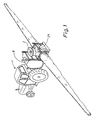
- Figure 1 illustrates a field spraying device according to the invention,
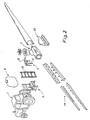
- Figure 2 is an exploded view of the spraying device of Figure 1,
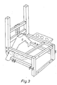
- Figure 3 illustrates the frame of Figure 2 on a larger scale,
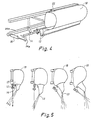
- Figure 4 illustrates a portion of the beam on a larger scale, and
- Figure 5 illustrates the inflatable hose with the longitudinal slot together with the nozzles for the liquid to be sprayed.
- As the crops differ it is necessary to have a possibility of attacking the plants in such a manner that the highest amount of liquid from the air flow comes into contact with the plants. In connection with sturdy, upright crops the spraying material must come into contact with the ground, and consequently the latter requires an air flow along the growing direction of the plants in order to ensure a maximum depositing of the spraying liquid.
- Thin, short crops come often into contact with a high amount of spraying liquid when the air-liquid flow follows a maximum distance from the top to the bottom of the plant to be sprayed. Weed control on ground without crops or with short crops at an early stage of the growth thereof also requires a rearward discharging or discharging at a predetermined angle of the air-liquid mixture. The air and the liquid cause the small plants to move in such a manner that both the bottom and the top side of the blades come into contact with the air-liquid flow. In addition it is of extreme importance that it is possible to spray along the inclination of the crop, because then it is possible to come into contact with and to deposit the liquid on the ground.
- The spraying is more or less sensitive to wind, especially when small nozzles and high pressures are involved. Usually large nozzles or low pressures are recommended in connection with sprayings where the surrounding wind is higher than 4-6 m/sec because the drop size is thereby increased. The latter is substantially caused by large drops possessing a higher energy than small drops. Accordingly, the large drops have a substantially better chance of coming into contact with the article to be sprayed. The air-liquid system has the effect that even the small wind-sensitive drops are fed with part of the energy of the controlled air flow, which prevents the surrounding air from removing the drops from the article to be sprayed.
- The system allows a spraying by means of small nozzles spraying only small amounts of liquid even at wind velocities exceeding 6 m/sec. As a result the capacity is higher than previously known.
- A movable slot system allows a spraying against the wind irrespective of the fact whether the vehicle follows the direction of the wind or not.
- The spraying device according to the invention provides an artificial wind which is utilized for stirring up the crop in such a manner that the spraying liquid can come into contact with the ground. A blower 2 (an axial blower) is used, and it is mounted on a centrally situated lift vehicle 4 on the spraying device in such a manner that the
blower 2 follows abeam 26 up and down. The tractor 1 carries the entire spraying device in a conventional three-point suspension. The spraying device comprises a frame 6 and acontainer 8 with the spraying liquid. The frame 6 is made of square steel pipes, cf. Figure 3. Twovertical side members 10 are secured to the frame 6, the lift vehicle 4 driving up and down theside members 10 by means of a hydraulic cylinder 11. The lift vehicle 4 is futhermore provided with a projecting fork 15 supporting thebeam 26. As a result theentire beam 26 can be moved up and down, which allows a variation of the height above the ground between 300 and 1900 mm. Thebeam 26 can be bent in two or more points in such a manner that it can be turned towards thecontainer 8 and the tractor 1. Thebeam 26 is provided withnozzles 12 at regular intervals of approximately 0.5 m. Thenozzles 12 communicate with aliquid distributor pipe 17. Thenozzles 12 and the air blown out of anelongated slot 13 must follow one another if the direction is varied. Thecontinuous slot 13 is provided at the bottom of thebeam 26, said slot only being interrupted in the bending points of thebeam 26. Theslot 13 is situated on apipe 14 and can be turned about said pipe in order to alter the angular position depending on whether it should be directed slightly for-ward or backward. The angular position of thepipe 14 is controlled by ahydraulic cylinder 16, one end of which is connected to arod 14a projecting from theturnable pipe 14, and the opposite end of which is connected to thecentral beam 26a. Hydraulic hoses (not shown) are connected to thehydraulic cylinders 16. Thepipe 14 is furthermore provided with several fittings supporting thenozzles 12 in such a manner that the liquid is sprayed into the air flow approximately 200-300 mm below the nozzle openings with the effect that the liquid drops sprayed out do not just flow away. Theslot 13 is preferably formed by means of rigid plastic members. The plastic members are shaped in such a manner that the rim of aflexible tarpaulin 18 can be pulled into two grooves and retained therein. Thetarpaulin 18 is made of plastics, where a rope is welded into each side, for instance in such a manner that the two ropes can be inserted in the grooves and retained therein. Thetarpaulin 18 is of a varying width and forms a elongated bag and is for instance made of DACRON (polyester canvas), PVC or polyethylene. A pipe of a diameter of approximately 100 mm at the end is provided. The diameter increases towards the center, and at theblower 2 it is about 500 mm. As a result, a uniform distribution of the air along theslot 13 is obtained. An air "carpet" must exist along the entire slot and in the same direction. Theaxial blower 2 with a vertical axis is situated at the center next to a T-shaped distributor pipe 3 of polyethylene distributing the air to the two channels formed by the elongated bags. Theblower 2 is hydraulicly driven in such a manner that it is possible to vary the velocity of the air from the slot from 0 to 30 m/sec. - At the innermost 2 m the air is removed through the side of the T-shaped member 3, a
separate bag 20 being situated at said member. - Each beam section is connected with a hose (not shown) feeding the liquid to be sprayed, said hose being connected to the
distributor pipe 17. The hydraulic cylinders turning the beam sections are connected to hydraulic hoses (not shown). The hydraulic hoses are fed by a hydraulic pump (not shown) and driven by the power output of the tractor. The hydraulic pump also feeds a hydraulic motor driving theaxial blower 2. Theblower 2 discharges about 1500 m³ per h per m of beam. As stated previously, a plurality ofhydraulic cylinders 16 are furthermore situated along thebeam 26 for the adjustment of the direction of thenozzles 12 and theair slot 13, respectively. - At the top the
bag 18 is secured to thebeam 26 by means of a number offittings 22, cf. Figure 4. - The
beam 26 is suspended in a trapezoidal beam system at 24, cf. FR-PS No. 1564543. Springs are futhermore provided which absorb possible shocks during the driving. - The invention thus provides a spraying device which is more flexible than previously known devices, and which improves the utilization of the materials sprayed out simultaneously with taking optimum care of the crop.
Claims (5)
Applications Claiming Priority (2)
| Application Number | Priority Date | Filing Date | Title |
|---|---|---|---|
| DK033688A DK167104B1 (en) | 1988-01-25 | 1988-01-25 | SPRAYER |
| DK336/88 | 1988-01-25 |
Publications (3)
| Publication Number | Publication Date |
|---|---|
| EP0326045A2 true EP0326045A2 (en) | 1989-08-02 |
| EP0326045A3 EP0326045A3 (en) | 1991-09-18 |
| EP0326045B1 EP0326045B1 (en) | 1994-10-19 |
Family
ID=8092388
Family Applications (1)
| Application Number | Title | Priority Date | Filing Date |
|---|---|---|---|
| EP89101021A Expired - Lifetime EP0326045B1 (en) | 1988-01-25 | 1989-01-20 | A field spraying device |
Country Status (6)
| Country | Link |
|---|---|
| US (1) | US4927080A (en) |
| EP (1) | EP0326045B1 (en) |
| AT (1) | ATE112931T1 (en) |
| AU (1) | AU617744B2 (en) |
| DE (1) | DE68918875T2 (en) |
| DK (1) | DK167104B1 (en) |
Cited By (6)
| Publication number | Priority date | Publication date | Assignee | Title |
|---|---|---|---|---|
| WO1993006721A1 (en) * | 1991-09-30 | 1993-04-15 | Her Majesty The Queen In The Right Of Canada As Represented By The Minister Of Forestry | Spraying apparatus |
| WO1998006257A1 (en) * | 1996-08-02 | 1998-02-19 | Hedegaard Albert | Method and sprayer boom for spraying a field crop with a plant protective liquid |
| EP0841006A1 (en) * | 1996-11-11 | 1998-05-13 | Greenland Nieuw-Vennep B.V. | Apparatus and method for applying liquid such as pesticides to the land |
| FR2853207A1 (en) * | 2003-04-07 | 2004-10-08 | Centre Nat Machinisme Agricole | Spray boom for agricultural vehicle has extruded metal section with integral channels for fluids and electrical connections |
| WO2017179973A1 (en) * | 2016-04-10 | 2017-10-19 | Henricus Johannes Godefridus Maria Hoeben | Spraying device for spraying liquid onto crops |
| EP3636074A1 (en) * | 2018-10-08 | 2020-04-15 | Blue River Technology Inc. | Nozzles with interchangeable inserts for precision application of crop protectant |
Families Citing this family (26)
| Publication number | Priority date | Publication date | Assignee | Title |
|---|---|---|---|---|
| US5176322A (en) * | 1986-08-29 | 1993-01-05 | Sartor Giuseppe M | Crop-spraying apparatus |
| FR2649336B2 (en) * | 1989-01-06 | 1994-06-03 | Tecnoma | DEVICE FOR SENDING A TREATMENT PRODUCT TO PLANTS |
| CA2002372C (en) * | 1989-11-07 | 1993-05-11 | Roger Reiter | Spray shield |
| US5098018A (en) * | 1990-09-28 | 1992-03-24 | Kibbuts Degania Bet | Crop spray apparatus having independently controlled drive assembly, operator's cab and spray device |
| US5680991A (en) * | 1992-07-29 | 1997-10-28 | Truitt; Archie Arthur | Air distribution system and sprayer incorporating an air distribution system |
| US5305548A (en) * | 1992-11-12 | 1994-04-26 | Siebol James R | Orchard heat exchanger |
| IL107455A (en) * | 1993-11-01 | 1998-03-10 | Durand Wayland | Orchard or grove sprayer |
| DK139693D0 (en) * | 1993-12-17 | 1993-12-17 | Hardi Int As | AIR CONDITION FOR AN AGRICULTURAL SPRAY |
| US5680993A (en) * | 1995-06-05 | 1997-10-28 | National Research Council Of Canada | Liquid atomizing device with controlled atomization and spray dispersion |
| US5961044A (en) * | 1997-07-31 | 1999-10-05 | Rite-Hite Holding Corporation | Misting apparatus and method |
| CA2277243C (en) | 1999-06-30 | 2007-08-07 | Bernard Panneton | Method and apparatus for spraying trees, plants and bushes |
| US6622935B1 (en) | 2000-08-23 | 2003-09-23 | American Tank & Equipment Co., Inc. | Articulated crop spraying apparatus |
| US6726120B2 (en) | 2001-12-19 | 2004-04-27 | Deere & Company | Automatic wind-drift compensation system for agricultural sprayers |
| US7121040B2 (en) * | 2002-07-08 | 2006-10-17 | The United States Of America As Represented By The Secretary Of Agriculture | Combination foliage compaction and treatment method and apparatus |
| AU2003901817A0 (en) * | 2003-04-16 | 2003-05-01 | The Crown in Right of the State of Queensland acting through the Department of Primary Industries & Fisheries (Forestry) | Hand operated agricultural chemical applicator |
| CA2433293A1 (en) * | 2003-06-25 | 2004-12-25 | H. William B. Wilt | Freely swinging self-levelling spray boom |
| JP4622313B2 (en) * | 2003-08-26 | 2011-02-02 | トヨタ自動車株式会社 | Moving body |
| US7225999B2 (en) * | 2004-09-23 | 2007-06-05 | The United States Of America As Represented By The Secretary Of The Navy | Spray array apparatus |
| EP2552594A4 (en) | 2010-04-02 | 2016-06-29 | Sta Rite Ind Llc | Air aspiration device |
| PT2590505E (en) * | 2010-07-06 | 2014-10-03 | Henricus Johannes Godefridus Maria Hoeben | Field crop spray apparatus for spraying crops with liquids |
| WO2015062964A1 (en) * | 2013-10-30 | 2015-05-07 | Agco Netherlands Bv | Agricultural sprayer boom |
| US9572308B1 (en) | 2014-05-30 | 2017-02-21 | K-B Agri Tech, LLC | Spray boom nozzle spoiler device and system |
| US10464080B1 (en) | 2017-01-16 | 2019-11-05 | Mark T. Hagberg | Retractable spray shield for agricultural use |
| US10315211B1 (en) | 2017-01-16 | 2019-06-11 | Mark T. Hagberg | Retractable spray shield for agricultural use |
| EP3679775A1 (en) * | 2019-01-08 | 2020-07-15 | Reichsgraf von Kesselstatt GmbH | Three-point combination frame |
| US20220331820A1 (en) * | 2021-04-20 | 2022-10-20 | Texas Transland LLC | Stainless Steel Spray Boom for Aerial Spraying |
Citations (2)
| Publication number | Priority date | Publication date | Assignee | Title |
|---|---|---|---|---|
| EP0272740A1 (en) | 1986-12-23 | 1988-06-29 | Van den Munckhof, Peter Marie Josef | Spray device |
| EP0278926A2 (en) | 1987-02-13 | 1988-08-17 | SIAPA Società Italo-Americana Prodotti Antiparassitari S.p.A. | Foldable spray boom for air atomization of chemical products on crop fields |
Family Cites Families (7)
| Publication number | Priority date | Publication date | Assignee | Title |
|---|---|---|---|---|
| US2836932A (en) * | 1955-09-01 | 1958-06-03 | Edwin B Potter | Portable crop saver |
| US3472454A (en) * | 1967-10-26 | 1969-10-14 | Subscription Television Inc | Low volume sprayer system |
| FR1564543A (en) * | 1968-01-04 | 1969-04-25 | ||
| US4274589A (en) * | 1977-07-29 | 1981-06-23 | A.C. Sprayers Inc. | Spraying apparatus employing a skirt structure |
| IL65871A0 (en) * | 1982-05-25 | 1982-08-31 | Degania Sprayers | Apparatus for spraying of field crops and the like |
| US4619216A (en) * | 1984-10-05 | 1986-10-28 | Crear Iii William | Sailboat luff system |
| US4583319A (en) * | 1985-06-27 | 1986-04-22 | Arcadian Corporation | Method of and apparatus for spraying foliar composition |
-
1988
- 1988-01-25 DK DK033688A patent/DK167104B1/en not_active IP Right Cessation
-
1989
- 1989-01-18 AU AU28593/89A patent/AU617744B2/en not_active Ceased
- 1989-01-20 EP EP89101021A patent/EP0326045B1/en not_active Expired - Lifetime
- 1989-01-20 AT AT89101021T patent/ATE112931T1/en not_active IP Right Cessation
- 1989-01-20 DE DE68918875T patent/DE68918875T2/en not_active Expired - Fee Related
- 1989-01-23 US US07/299,415 patent/US4927080A/en not_active Expired - Lifetime
Patent Citations (2)
| Publication number | Priority date | Publication date | Assignee | Title |
|---|---|---|---|---|
| EP0272740A1 (en) | 1986-12-23 | 1988-06-29 | Van den Munckhof, Peter Marie Josef | Spray device |
| EP0278926A2 (en) | 1987-02-13 | 1988-08-17 | SIAPA Società Italo-Americana Prodotti Antiparassitari S.p.A. | Foldable spray boom for air atomization of chemical products on crop fields |
Non-Patent Citations (1)
| Title |
|---|
| AGRICULTURAL MACHINERY JOURNAL, vol. 41, no. 2, February 1987 (1987-02-01), pages 28 |
Cited By (14)
| Publication number | Priority date | Publication date | Assignee | Title |
|---|---|---|---|---|
| WO1993006721A1 (en) * | 1991-09-30 | 1993-04-15 | Her Majesty The Queen In The Right Of Canada As Represented By The Minister Of Forestry | Spraying apparatus |
| US5246166A (en) * | 1991-09-30 | 1993-09-21 | Her Majesty The Queen In The Right Of Canada As Represented By The Minister Of Forestry | Spraying apparatus |
| US5443210A (en) * | 1991-09-30 | 1995-08-22 | Her Majesty The Queen In The Right Of Canada, As Represented By The Minister Of Energy, Mines, Resources And Forestry | Spraying apparatus |
| AU663892B2 (en) * | 1991-09-30 | 1995-10-26 | Her Majesty The Queen In The Right Of Canada As Represented By The Minister Of Forestry | Spraying apparatus |
| WO1998006257A1 (en) * | 1996-08-02 | 1998-02-19 | Hedegaard Albert | Method and sprayer boom for spraying a field crop with a plant protective liquid |
| US6126084A (en) * | 1996-08-02 | 2000-10-03 | Hedegaard; Albert | Method and sprayer boom for spraying a field crop with a plant protective liquid |
| NL1004495C2 (en) * | 1996-11-11 | 1998-05-14 | Greenland Nieuw Vennep Bv | Device and method for applying liquid on land, such as pesticides. |
| EP0841006A1 (en) * | 1996-11-11 | 1998-05-13 | Greenland Nieuw-Vennep B.V. | Apparatus and method for applying liquid such as pesticides to the land |
| FR2853207A1 (en) * | 2003-04-07 | 2004-10-08 | Centre Nat Machinisme Agricole | Spray boom for agricultural vehicle has extruded metal section with integral channels for fluids and electrical connections |
| EP1468605A1 (en) * | 2003-04-07 | 2004-10-20 | Centre National Du Machinisme Agricole, Du Genie Rural, Des Eaux Et Des Forets (Cemagref) | Spray boom |
| WO2017179973A1 (en) * | 2016-04-10 | 2017-10-19 | Henricus Johannes Godefridus Maria Hoeben | Spraying device for spraying liquid onto crops |
| EP3636074A1 (en) * | 2018-10-08 | 2020-04-15 | Blue River Technology Inc. | Nozzles with interchangeable inserts for precision application of crop protectant |
| US11071293B2 (en) | 2018-10-08 | 2021-07-27 | Blue River Technology Inc. | Nozzles with interchangeable inserts for precision application of crop protectant |
| US11992004B2 (en) | 2018-10-08 | 2024-05-28 | Blue River Technology Inc. | Nozzles with interchangeable inserts for precision application of crop protectant |
Also Published As
| Publication number | Publication date |
|---|---|
| EP0326045B1 (en) | 1994-10-19 |
| US4927080A (en) | 1990-05-22 |
| DK33688A (en) | 1989-07-26 |
| DK167104B1 (en) | 1993-08-30 |
| ATE112931T1 (en) | 1994-11-15 |
| EP0326045A3 (en) | 1991-09-18 |
| AU617744B2 (en) | 1991-12-05 |
| DE68918875D1 (en) | 1994-11-24 |
| AU2859389A (en) | 1989-07-27 |
| DE68918875T2 (en) | 1995-06-08 |
| DK33688D0 (en) | 1988-01-25 |
Similar Documents
| Publication | Publication Date | Title |
|---|---|---|
| EP0326045A2 (en) | A field spraying device | |
| US7080961B1 (en) | Distribution assembly for particulate material | |
| US4798325A (en) | Method and apparatus for applying liquid and dry lawn treatment materials | |
| US5897057A (en) | Controlled atmosphere transfer system | |
| CZ173496A3 (en) | Agricultural sprinkling unit and a system for producing air jet of the agricultural sprinkling unit | |
| AU2010101181A4 (en) | Horticulture Tree Sprayer Function and Simple Adjustment | |
| US20060131444A1 (en) | Spraying apparatus | |
| US6820828B1 (en) | Circle irrigation chemical application | |
| US4709860A (en) | System for applying pesticides without drift | |
| US4659013A (en) | Spray unit for controlled droplet atomization | |
| AU2007100326A4 (en) | Horticulture tree spray system | |
| US5419493A (en) | Agricultural chemical distributor | |
| US5520335A (en) | Spray hood and assembly including the spray hood | |
| US5993903A (en) | Apparatus and method for treating seed | |
| US5435493A (en) | Manure distributor with atop discharge pipes and manure spreader incorporating the same | |
| US5402945A (en) | Method for spraying plants and apparatus for its practice | |
| US5383599A (en) | Agricultural air/liquid sprayer having an inflatable spraying sleeve | |
| EP0319531A4 (en) | Crop-spraying apparatus | |
| EP0549058A1 (en) | Tunnel-like spray device | |
| US4892256A (en) | Up-spray deflector cup for spraying the underside of plant foliage | |
| US4669662A (en) | Mobile spray apparatus | |
| US4168801A (en) | Discharge assembly for liquid manure spreader | |
| US3228144A (en) | Apparatus for applying finely divided material to plants | |
| US10136575B2 (en) | Product row banding assembly for air delivery machines | |
| EP0404927B1 (en) | Agricultural machine comprising a harrow and sow device |
Legal Events
| Date | Code | Title | Description |
|---|---|---|---|
| PUAI | Public reference made under article 153(3) epc to a published international application that has entered the european phase |
Free format text: ORIGINAL CODE: 0009012 |
|
| AK | Designated contracting states |
Kind code of ref document: A2 Designated state(s): AT BE CH DE ES FR GB IT LI NL SE |
|
| PUAL | Search report despatched |
Free format text: ORIGINAL CODE: 0009013 |
|
| AK | Designated contracting states |
Kind code of ref document: A3 Designated state(s): AT BE CH DE ES FR GB IT LI NL SE |
|
| 17P | Request for examination filed |
Effective date: 19911016 |
|
| 17Q | First examination report despatched |
Effective date: 19911209 |
|
| RAP1 | Party data changed (applicant data changed or rights of an application transferred) |
Owner name: HARDI INTERNATIONAL A/S |
|
| GRAA | (expected) grant |
Free format text: ORIGINAL CODE: 0009210 |
|
| AK | Designated contracting states |
Kind code of ref document: B1 Designated state(s): AT BE CH DE ES FR GB IT LI NL SE |
|
| PG25 | Lapsed in a contracting state [announced via postgrant information from national office to epo] |
Ref country code: ES Free format text: THE PATENT HAS BEEN ANNULLED BY A DECISION OF A NATIONAL AUTHORITY Effective date: 19941019 Ref country code: LI Effective date: 19941019 Ref country code: CH Effective date: 19941019 Ref country code: AT Effective date: 19941019 |
|
| REF | Corresponds to: |
Ref document number: 112931 Country of ref document: AT Date of ref document: 19941115 Kind code of ref document: T |
|
| REF | Corresponds to: |
Ref document number: 68918875 Country of ref document: DE Date of ref document: 19941124 |
|
| ET | Fr: translation filed | ||
| ITF | It: translation for a ep patent filed | ||
| PG25 | Lapsed in a contracting state [announced via postgrant information from national office to epo] |
Ref country code: SE Effective date: 19950119 |
|
| REG | Reference to a national code |
Ref country code: CH Ref legal event code: PL |
|
| PLBE | No opposition filed within time limit |
Free format text: ORIGINAL CODE: 0009261 |
|
| STAA | Information on the status of an ep patent application or granted ep patent |
Free format text: STATUS: NO OPPOSITION FILED WITHIN TIME LIMIT |
|
| 26N | No opposition filed | ||
| PGFP | Annual fee paid to national office [announced via postgrant information from national office to epo] |
Ref country code: BE Payment date: 19990209 Year of fee payment: 11 |
|
| PG25 | Lapsed in a contracting state [announced via postgrant information from national office to epo] |
Ref country code: BE Free format text: LAPSE BECAUSE OF NON-PAYMENT OF DUE FEES Effective date: 20000131 |
|
| BERE | Be: lapsed |
Owner name: HARDI INTERNATIONAL A/S Effective date: 20000131 |
|
| REG | Reference to a national code |
Ref country code: GB Ref legal event code: IF02 |
|
| PGFP | Annual fee paid to national office [announced via postgrant information from national office to epo] |
Ref country code: GB Payment date: 20060103 Year of fee payment: 18 |
|
| PGFP | Annual fee paid to national office [announced via postgrant information from national office to epo] |
Ref country code: FR Payment date: 20060131 Year of fee payment: 18 Ref country code: NL Payment date: 20060131 Year of fee payment: 18 Ref country code: IT Payment date: 20060131 Year of fee payment: 18 |
|
| PGFP | Annual fee paid to national office [announced via postgrant information from national office to epo] |
Ref country code: DE Payment date: 20060323 Year of fee payment: 18 |
|
| PG25 | Lapsed in a contracting state [announced via postgrant information from national office to epo] |
Ref country code: DE Free format text: LAPSE BECAUSE OF NON-PAYMENT OF DUE FEES Effective date: 20070801 |
|
| GBPC | Gb: european patent ceased through non-payment of renewal fee |
Effective date: 20070120 |
|
| NLV4 | Nl: lapsed or anulled due to non-payment of the annual fee |
Effective date: 20070801 |
|
| REG | Reference to a national code |
Ref country code: FR Ref legal event code: ST Effective date: 20070930 |
|
| PG25 | Lapsed in a contracting state [announced via postgrant information from national office to epo] |
Ref country code: GB Free format text: LAPSE BECAUSE OF NON-PAYMENT OF DUE FEES Effective date: 20070120 |
|
| PG25 | Lapsed in a contracting state [announced via postgrant information from national office to epo] |
Ref country code: NL Free format text: LAPSE BECAUSE OF NON-PAYMENT OF DUE FEES Effective date: 20070801 |
|
| PG25 | Lapsed in a contracting state [announced via postgrant information from national office to epo] |
Ref country code: FR Free format text: LAPSE BECAUSE OF NON-PAYMENT OF DUE FEES Effective date: 20070131 |
|
| PG25 | Lapsed in a contracting state [announced via postgrant information from national office to epo] |
Ref country code: IT Free format text: LAPSE BECAUSE OF NON-PAYMENT OF DUE FEES Effective date: 20070120 |