EP0325694A2 - Kompressor - Google Patents
Kompressor Download PDFInfo
- Publication number
- EP0325694A2 EP0325694A2 EP88116326A EP88116326A EP0325694A2 EP 0325694 A2 EP0325694 A2 EP 0325694A2 EP 88116326 A EP88116326 A EP 88116326A EP 88116326 A EP88116326 A EP 88116326A EP 0325694 A2 EP0325694 A2 EP 0325694A2
- Authority
- EP
- European Patent Office
- Prior art keywords
- housing
- compressor
- pin
- apertures
- sidewall
- Prior art date
- Legal status (The legal status is an assumption and is not a legal conclusion. Google has not performed a legal analysis and makes no representation as to the accuracy of the status listed.)
- Granted
Links
Images


Classifications
-
- F—MECHANICAL ENGINEERING; LIGHTING; HEATING; WEAPONS; BLASTING
- F04—POSITIVE - DISPLACEMENT MACHINES FOR LIQUIDS; PUMPS FOR LIQUIDS OR ELASTIC FLUIDS
- F04B—POSITIVE-DISPLACEMENT MACHINES FOR LIQUIDS; PUMPS
- F04B39/00—Component parts, details, or accessories, of pumps or pumping systems specially adapted for elastic fluids, not otherwise provided for in, or of interest apart from, groups F04B25/00 - F04B37/00
- F04B39/14—Provisions for readily assembling or disassembling
-
- F—MECHANICAL ENGINEERING; LIGHTING; HEATING; WEAPONS; BLASTING
- F04—POSITIVE - DISPLACEMENT MACHINES FOR LIQUIDS; PUMPS FOR LIQUIDS OR ELASTIC FLUIDS
- F04B—POSITIVE-DISPLACEMENT MACHINES FOR LIQUIDS; PUMPS
- F04B39/00—Component parts, details, or accessories, of pumps or pumping systems specially adapted for elastic fluids, not otherwise provided for in, or of interest apart from, groups F04B25/00 - F04B37/00
- F04B39/12—Casings; Cylinders; Cylinder heads; Fluid connections
- F04B39/127—Mounting of a cylinder block in a casing
-
- F—MECHANICAL ENGINEERING; LIGHTING; HEATING; WEAPONS; BLASTING
- F05—INDEXING SCHEMES RELATING TO ENGINES OR PUMPS IN VARIOUS SUBCLASSES OF CLASSES F01-F04
- F05C—INDEXING SCHEME RELATING TO MATERIALS, MATERIAL PROPERTIES OR MATERIAL CHARACTERISTICS FOR MACHINES, ENGINES OR PUMPS OTHER THAN NON-POSITIVE-DISPLACEMENT MACHINES OR ENGINES
- F05C2201/00—Metals
- F05C2201/04—Heavy metals
- F05C2201/0469—Other heavy metals
- F05C2201/0475—Copper or alloys thereof
- F05C2201/0478—Bronze (Cu/Sn alloy)
-
- Y—GENERAL TAGGING OF NEW TECHNOLOGICAL DEVELOPMENTS; GENERAL TAGGING OF CROSS-SECTIONAL TECHNOLOGIES SPANNING OVER SEVERAL SECTIONS OF THE IPC; TECHNICAL SUBJECTS COVERED BY FORMER USPC CROSS-REFERENCE ART COLLECTIONS [XRACs] AND DIGESTS
- Y10—TECHNICAL SUBJECTS COVERED BY FORMER USPC
- Y10S—TECHNICAL SUBJECTS COVERED BY FORMER USPC CROSS-REFERENCE ART COLLECTIONS [XRACs] AND DIGESTS
- Y10S417/00—Pumps
- Y10S417/902—Hermetically sealed motor pump unit
Definitions
- the present invention relates generally to a hermetic compressor assembly and, more particularly, to such a compressor assembly having a compressor mechanism mounted in a hermetically sealed housing, wherein it is desired to mount the compressor mechanism to provide an air gap between the rotor and stator components of the compressor motor, and to prevent relative movement between the compressor mechanism and the housing due to torque forces produced by the motor.
- a typical hermetic compressor assembly comprises a compressor mechanism and an electric motor situated within a hermetically housing.
- the electric motor comprises a stator member and a rotatable rotor operably spaced from the stator by an annular air gap.
- the compressor mechanism is a rotary compressor
- a cylinder block or main bearing flange is circumferentially mounted to the inside wall of the housing and a crankshaft is journalled in bearings on opposite sides of the cylinder block.
- One end of the crankshaft is press fit into the center of the rotor which, in turn, is spaced from the stator.
- the motor stator is circumferentially friction fit against the inside wall of the housing.
- a scotch yoke compressor comprising a crankcase having a circumferential flange member mountable to the interior wall of the housing.
- a crankshaft with a rotor attached thereto is journalled in axially aligned bearings in the housing.
- the motor stator is mounted to the crankcase member to facilitate axial alignment of the rotor and stator prior to mounting the compressor mechanism assembly within the housing.
- dynamic operation of the motor during starting and stopping imparts a torque force to the crankcase and mounting flange, which tends to cause relative rotational movement between the crankcase and the housing. It is desirable to avoid such rotational movement between the crankcase and housing due to the fact that, for a direct suction compressor wherein a suction tube extends from the housing to the crankcase, damage may result to the suction tube due to stress placed thereon.
- the present invention overcomes the disadvantages of the above-described prior art mounting methods for hermetically sealed compressors by providing an improved compressor mounting system for mounting a compressor cylinder block or crankcase within a sealed housing to provide an air gap between the motor stator and rotor and to prevent rotation of the compressor mechanism within the housing.
- the invention provides a hermetically sealed compressor assembly comprising a housing wherein a compressor mechanism, including a frame member, is enclosed therein.
- a compressor mechanism including a frame member
- An aperture is provided in the sidewall of the housing and a radially outwardly opening hole is provided in the frame member.
- a pin member is received within the hole and extends radially outwardly through the aperture and is welded thereto.
- the invention provides, in one form thereof, a mounting apparatus for mounting a compressor mechanism within a housing.
- a plurality of mounting pins received within holes in the compressor mechanism frame extend radially outwardly through oversized apertures in the housing sidewall.
- the compressor mechanism is properly oriented to provide an air gap between the motor rotor and stator by positioning the pins within the oversized apertures and then welding the pins to the housing when the proper orientation is achieved.
- a compressor mechanism axially supported in the housing is prevented from rotating by a single pin extending radially outwardly from a hole in the compressor mechanism frame into an aperture in the housing sidewall to which the pin is welded.
- An advantage of the structure of the present invention is that a proper air gap between the motor rotor and stator is easily achieved during compressor assembly.
- Another advantage of the mounting system of the present invention is that a better weld connection is achieved between the mounting pin and compressor housing than is possible between the compressor crankcase and housing.
- a still further advantage of the mounting system of the present invention is that the use of three circumferentially spaced mounting pins does not allow the compressor mechanism to move with respect to the housing.
- a still further advantage of the mounting system of the present invention is that rotational movement of the compressor mechanism with respect to the housing is prevented by the use of a single mounting pin, which also prevents binding of the compressor crankcase in the housing which produces undesirable noise.
- Another advantage of the mounting system of the present invention is that rotational forces imparted to the compressor mechanism and causing relative rotational movement between the compressor mechanism and the housing are prevented from placing stress on the suction line adapter.
- Another advantage of the mounting system of the present invention is that machining tolerances of various compressor assembly components are compensated for in assembly by the provision of a mounting pin selectively positionable within an oversized aperture.
- the mounting apparatus of the present invention in one form thereof, relates to a compressor assembly comprising a compressor mechanism within a hermetically sealed housing having a sidewall, where the compressor mechanism includes a frame member.
- the invention provides for an aperture in the sidewall, a radially outwardly opening hole in the frame member, a pin member received within the hole and extending radially outwardly substantially through the aperture, and means for attaching the pin member to the housing at the location of the aperture such that the housing remains hermetically sealed.
- a hermetically sealed rotary compressor including a cylindrical housing having a sidewall.
- a compressor mechanism having a frame member and an electric motor having a stator secured to the housing.
- the motor also includes a rotatable rotor operably associated with the stator and separated therefrom by an annular air gap.
- a crankshaft is rotatably connected to the rotor and is journalled in the frame member.
- the invention relates specifically to a mounting apparatus for mounting the frame member to the sidewall to provide for the air gap, and comprises a plurality of radially outwardly opening holes in the frame member spaced circumferentially thereabout.
- a plurality of apertures are provided in the sidewall and are spaced circumferentially thereabout, whereby each aperture corresponds to and is substantially aligned with a respective aperture.
- a plurality of pin members are provided, each being associated with a respective hole and aperture pair. Each pin member is received within the hole and extends radially outwardly through a corresponding aperture. The pin member is shaped and sized to be selectively positioned within the aperture.
- the present invention also includes weldment means for attaching the pin members to the housing with the pin members selectively positioned within the aperture such that said air gap is provided.
- the means for attaching the pin members includes a connection between each one of the pin members and its corresponding aperture about the perimeter thereof such that the housing remains hermetically sealed.
- the present invention further provides, in one form thereof, a compressor assembly comprising a hermetically sealed cylindrical housing having a cylindrical sidewall about a vertical main axis.
- a compressor mechanism within the housing includes a frame member and an electric motor mounted to the frame member.
- the invention more specifically provides for mounting the compressor mechanism within a housing by an apparatus comprising means for axially supporting the frame member within the housing.
- means are provided for preventing rotational movement of the frame member with respect to the vertical axis which ordinarily results from torque forces imparted to the frame member by dynamic operation of the motor.
- the preventing means comprises a pin member received within a hole defined by the frame member and which extends through an aperture in the housing sidewall. The pin member is sealingly connected to the housing at the location of the aperture.
- a method of assembling a hermetically sealed rotary compressor is provided according to the present invention, in one form thereof, wherein the compressor includes a housing having a cylindrical sidewall, a compressor mechanism having a frame member and a crankshaft journalled therein.
- An electric motor is provided having a stator and a rotatable rotor separated one from the other by a desired annular air gap.
- the rotor is operably coupled to the crankshaft.
- the method of the present invention in one form thereof, comprises steps of mounting the stator within the housing and placing the compressor mechanism, together with the rotor operably coupled thereto, within the housing such that the rotor and the stator are separated by the desired annular air gap.
- a further step is to provide a plurality of apertures in the sidewall of the housing spaced circumferentially thereabout.
- Another step is to provide a plurality of holes in the frame member, opening radially outwardly at circumferentially spaced locations corresponding to the apertures.
- Yet another step of the assembly method is to provide a plurality of pin members each having a first frame end and a second housing end.
- the frame end of each one of the pin members is inserted into a respective hole such that the housing end extends radially outwardly into a corresponding aperture in the housing.
- a welding step is also performed wherein the housing end of each pin member is welded to the housing at the location of a corresponding aperture such that a hermetic seal is maintained for the housing. Accordingly, the compressor mechanism is mounted to the sidewall to achieve a desired air gap between the rotor and the stator.
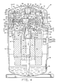
- a compressor having a housing generally designated at 310.
- the housing has a top portion 312, a lower portion 314 and a central portion 316.
- the three housing portions are hermetically secured together as by welding or brazing.
- a flange 318 is welded to the bottom of housing 310 for mounting the compressor.
- a motor Located inside the hermetically sealed housing is a motor generally designated at 320 having a stator 322 and a rotor 324 operably spaced from one another by an annular air gap 325.
- the stator is provided with windings 326.
- the stator is secured to the housing 310 by an interference fit such as by shrink fitting.
- the rotor 324 has a central aperture 328 provided therein into which is secured a crankshaft 330 by an interference fit.
- a terminal cluster 332 is provided on the top portion 312 of the compressor for connecting the compressor to a source of electric power.
- a post 334 is welded to top portion 312 for mounting a protective cover (not shown) for terminal cluster 332.
- a refrigerant discharge tube 336 extends through top portion 312 of the housing and has an end 338 thereof extending into the interior of the compressor as shown.
- the tube is sealingly connected to housing 310 at 340 as by soldering.
- a suction tube 342 extends into the interior of compressor housing 310 and is sealed thereto as by soldering, brazing, or welding.
- Suction tube 342 further extends into and is sealingly received within a suction inlet opening 343.
- the outer end 344 of suction tube 342 is connected to accumulator 346 which has support plates 348 disposed therein for supporting a filtering mesh 350.
- a bracket 352 secures accumulator 346 to the outside wall of housing 310.
- Crankshaft 330 is provided with an eccentric portion 354 which revolves around the crankshaft axis as crankshaft 330 is rotatably driven by rotor 324.
- Counterweights 356 and 358 are provided to balance eccentric 354 and are secured to respective end rings 360 and 362 of rotor 324 by riveting.
- Crankshaft 330 is journalled in a main bearing 364 having a cylindrical journal portion 366 and a generally flat planar mounting portion 368 including flanges 372.
- Planar portion 368 is secured to housing 310 by means of three mounting pin assemblies 370, in accord with the present invention, as will be described in more detail with reference to Figs. 2 and 3.
- a second bearing or journal 374 is also shown disposed in the lower part of housing 310.
- Outboard bearing 374 is provided with a journal portion 376 having aperture 378 therein and a generally planar portion 380.
- Crankshaft 330 has a lower portion 382 journalled in journal portion 376 of outboard bearing 374 as illustrated in Fig. 1.
- Cylinder block 384 Located intermediate main bearing 364 and outboard bearing 374 is a compressor cylinder block 384.
- Cylinder block 384 includes a cylinder therein, referred to herein as compression chamber 385.
- Compressor cylinder block 384, outboard bearing 374, and main bearing 364 are secured together by means of twelve bolts 386, two of which are indicated in Fig. 1.
- twelve bolts 386 two of which are indicated in Fig. 1.
- six threaded holes 388 are provided in cylinder block 384 for securing bearings 364, 374 and cylinder block 384 together. Of the twelve bolts 386, six of them secure outboard bearing 374 to cylinder block 384 and are threaded into holes 388.
- main bearing 364 secures main bearing 364 to cylinder block 384 and are also threaded into holes 388.
- An upper discharge muffler plate 390 is secured to main bearing 364 and a lower discharge muffler plate 392 is secured to outboard bearing 374 by bolts 386, as indicated in Fig. 1.
- cylinder block 384 has a vane slot 394 provided in the cylindrical sidewall 396 thereof into which is received a sliding vane 398.
- Roller 400 is provided which surrounds eccentric portion 354 of crankshaft 330 and revolves around the axis of crankshaft 330 and is driven by eccentric 354. Tip 402 of sliding vane 398 is in continuous engagement with roller 400 as vane 398 is urged against the roller by spring 404 received in spring pocket 406.
- spring 404 received in spring pocket 406.
- roller 400 the compression volume enclosed by roller 400, cylinder wall 396, and sliding vane 398 will decrease in size as roller 400 revolves clockwise around compression chamber 385. Refrigerant contained in that volume will therefore be compressed and after compression will exit through a relief 410 in sidewall 396.
- a discharge muffling system is provided in the embodiment of Figs. 1 and 2, whereby compressed gas exiting through relief 410 passes through main bearing 364 and outboard bearing 374 into mufflers defined by upper muffler plate 390 and lower muffler 392, respectively. The gas from the mufflers is then discharged into the interior of housing 310.
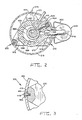
- flanges 372 are provided with radially outwardly opening holes 412 in a radially outward facing flange surface 414.
- Corresponding apertures 416 are provided in central portion 316 of housing 310 such that holes 412 and respective apertures 416 are substantially axially aligned.
- a scroll pin 418 is frictionally slidably engaged within each hole 412 and extends radially outwardly into a corresponding aligned aperture 416.
- aperture 416 is oversized with respect to the diameter of scroll pin 418 to allow for selective positioning of scroll pin 418 within aperture 416.
- an annular clearance of .030 is provided where the diameter of the pin is 3/8 inches and the diameter of the aperture is 7/16 inches.
- the rotary compressor within housing 310 is selectively positioned and mounted to achieve a proper air gap 325 between rotor 324 and stator 320.
- scroll pins 418 are attached, as by welding, to central portion 316 of the housing, as indicated in Fig. 2 by weldment 420.
- Weldment 420 extends between scroll pin 418 and central portion 316 at the location of aperture 416, to ensure that housing 310 remains hermetically sealed. It is appreciated that weldment 420 may alternatively take the form of brazing, epoxy, or the like, without departing from the spirit and scope of the present invention.
- Scroll pin 418 as defined herein, comprises a spirally wound band of cold rolled steel, or the like. While such a wound, cylindrical pin exhibits superior welding properties in the present application, it is appreciated that other pins may be used without departing from the scope of the present invention.
- the disclosed preferred embodiment of the present invention provides three equally circumferentially spaced mounting pin assemblies 370 for mounting the compressor mechanism within the housing. In such an arrangement the compressor mechanism is restrained against movement, while the housing is permitted to radially expand and contract in response to varying housing temperature and pressure conditions.
- the present invention also contemplates a method for assembling a rotary compressor within a housing to ensure a desired annular air gap between a motor stator and rotor. More specifically, with reference to Figs. 1-3, the method of the present invention comprises mounting stator 322 within central portion 316 as by a friction fit. The rotary compressor mechanism, together with rotor 324 coupled thereto, is then inserted into the housing such that the rotor and stator are separated by a desired annular air gap. The desired air gap may be maintained during assembly by means of a locating pin temporarily received within suction inlet opening 343, and a gap collar, such as a thin cylindrical metal shell located between the rotor and stator.
- a plurality of circumferentially spaced apertures 416 are provided in the sidewall of central portion 316.
- the method also includes the provision of a plurality of holes 412 in main bearing 364 such that the holes open radially outwardly at circumferentially spaced locations corresponding to apertures 416. Holes 412 and apertures 416 are generally aligned when the rotary compressor is in proper position within the housing. Scroll pins 418 are then inserted through apertures 416 into holes 412, with a portion of the pin remaining within aperture 416 or protruding slightly therefrom. After the compressor mechanism is selectively positioned to achieve the desired annular air gap, pins 418 are welded to central portion 316 of the housing so as to provide a hermetic seal to the housing.
- a compressor assembly 10 having a housing generally designated at 12.
- the housing has a top portion 14, a central portion 16, and a bottom portion 18.
- the three housing portions are hermetically secured together as by welding or brazing.
- a mounting flange 20 is welded to the bottom portion 18 for mounting the compressor in a vertically upright position.
- an electric motor generally designated at 22 having a stator 24 and a rotor 26.
- the stator is provided with windings 28.
- Rotor 26 has a central aperture 30 provided therein into which is secured a crankshaft 32 by an interference fit.
- a terminal cluster 34 is provided in central portion 16 of housing 12 for connecting the compressor to a source of electric power. Where electric motor 22 is a three-phase motor, bidirectional operation of compressor assembly 10 is achieved by changing the connection of power at terminal cluster 34.
- Compressor assembly 10 also includes an oil sump 36 located in bottom portion 18.
- An oil sight glass 38 is provided in the sidewall of bottom portion 18 to permit viewing of the oil level in sump 36.
- a centrifugal oil pick-up tube 40 is press fit into a counterbore 42 in the end of crankshaft 32.
- Oil pick-up tube 40 is of conventional construction and includes a vertical paddle (not shown) enclosed therein.
- Compressor mechanism 44 comprises a crankcase 46 including a plurality of mounting lugs 48 to which motor stator 24 is attached such that there is an annular air gap 50 between stator 24 and rotor 26.
- Crankcase 46 also includes a circumferential mounting flange 52 axially supported within an annular ledge 54 in central portion 16 of the housing.
- a bore 236 extends through flange 52 to provide communication between the top and bottom ends of housing 12 for return of lubricating oil and equalization of discharge pressure within the entire housing interior.
- Compressor mechanism 44 takes the form of a reciprocating piston, scotch yoke compressor. More specifically, crankcase 46 includes four radially disposed cylinders, two of which are shown in Fig. 4 and designated as cylinder 56 and cylinder 58. The four radially disposed cylinders open into and communicate with a central suction cavity 60 defined by inside cylindrical wall 62 in crankcase 46. A relatively large pilot hole 64 is provided in a top surface 66 of crankcase 46. Various compressor components, including the crankshaft, are assembled through pilot hole 64. A top cover such as cage bearing 68 is mounted to the top surface of crankcase 46 by means of a plurality of bolts 70 extending through bearing 68 into top surface 66. When bearing 68 is assembled to crankcase 46, an O-ring seal 72 isolates suction cavity 60 from a discharge pressure space 74 defined by the interior of housing 12.
- Crankcase 46 further includes a bottom surface 76 and a bearing portion 78 extending therefrom.
- a sleeve bearing assembly comprising a pair of sleeve bearings 80 and 82. Two sleeve bearings are preferred rather than a single longer sleeve bearing to facilitate easy assembly into bearing portion 78.
- a sleeve bearing 84 is provided in cage bearing 68, whereby sleeve bearings 80, 82, and 84 are in axial alignment.
- Sleeve bearings 80, 82, and 84 are manufactured from steel-backed bronze.
- a sleeve bearing as referred to herein, is defined as a generally cylindrical bearing surrounding and providing radial support to a cylindrical portion of a crankshaft, as opposed to a thrust bearing which provides axial support for the weight of the crankshaft and associated parts.
- a sleeve bearing for example, may comprise a steel-backed bronze sleeve insertable into a crankcase, or a machined cylindrical surface made directly in the crankcase casting or another frame member.
- crankshaft 32 there is provided thereon journal portions 86 and 88, wherein journal portion 86 is received within sleeve bearings 80 and 82, and journal portion 88 is received within sleeve bearing 84. Accordingly, crankshaft 32 is rotatably journalled in crankcase 46 and extends through a suction cavity 60.
- Crankshaft 32 includes a counterweight portion 90 and an eccentric portion 92 located opposite one another with respect to the central axis of rotation of crankshaft 32 to thereby counterbalance one another. The weight of crankshaft 32 and rotor 26 is supported on thrust surface 93 of crankcase 46.
- Eccentric portion 92 is operably coupled by means of a scotch yoke mechanism 94 to a plurality of reciprocating piston assemblies corresponding to, and operably disposed within, the four radially disposed cylinders in crankcase 46.
- piston assemblies 96 and 98 representative of four radially disposed piston assemblies operable in compressor assembly 10, are associated with cylinders 56 and 58, respectively.
- Scotch yoke mechanism 94 comprises a slide block 100 including a cylindrical bore 102 in which eccentric portion 92 is journalled.
- cylindrical bore 102 is defined by a steel backed bronze sleeve bearing press fit within slide block 100.
- a reduced diameter portion 103 in crankshaft 32 permits easy assembly of slide block 100 onto eccentric portion 92.
- Scotch yoke mechanism 94 also includes a pair of yoke members 104 and 106 which cooperate with slide block 100 to convert orbiting motion of eccentric portion 92 to reciprocating movement of the four radially disposed piston assemblies.
- Fig. 4 shows yoke member 106 coupled to piston assemblies 96 and 98, whereby when piston assembly 96 is at a bottom dead center (BDC) position, piston assembly 98 will be at a top dead center (TDC) position.
- each piston assembly comprises a piston member 108 having an annular piston ring 110 to allow piston member 108 to reciprocate within a cylinder to compress gaseous refrigerant therein.
- Suction ports 112 extending through piston member 108 allow suction gas within suction cavity 60 to enter cylinder 56 on the compression side of piston 108.
- Suction valve assembly 114 is also associated with each piston assembly, and will now be described with respect to piston assembly 96 shown in Fig. 4.
- Suction valve assembly 116 comprises a flat, disk-shaped suction valve 116 which in its closed position covers suction ports 112 on a top surface 118 of piston member 108.
- Suction valve 116 opens and closes by virtue of its own inertia as piston assembly 96 reciprocates in cylinder 56. More specifically, suction valve 116 rides along a cylindrical guide member 120 and is limited in its travel to an open position by an annular valve retainer 122.
- valve retainer 122, suction valve 116, and guide member 120 are secured to top surface 118 of piston member 108 by a threaded bolt 124 having a buttonhead 128. Threaded bolt 124 is received within a threaded hole 126 in yoke member 106 to secure piston assembly 96 thereto. As shown with respect to the attachment of piston assembly 98 to yoke member 106, an annular recess 130 is provided in each piston member and a complementary boss 132 is provided on the corresponding yoke member, whereby boss 132 is received within recess 130 to promote positive, aligned engagement therebetween.
- Valve plate 136 includes a coined recess 140 into which buttonhead 128 of threaded bolt 124 is received when piston assembly 98 is positioned at top dead center (TDC).
- a discharge valve assembly 142 is situated on a top surface 144 of valve plate 136.
- compressed gaseous refrigerant is discharged through valve plate 136 past an open discharge valve 146 that is limited in its travel by a discharge valve retainer 148.
- Guide pins 150 and 152 extend between valve plate 136 and cylinder head cover 134, and guidingly engage holes in discharge valve 146 and discharge valve retainer 148 at diametrically opposed locations therein.
- Valve retainer 148 is biased against cylinder head cover 134 to normally retain discharge valve 146 against top surface 144 at the diametrically opposed locations.
- excessively high mass flow rates of discharge gas or hydraulic pressures caused by slugging may cause valve 146 and retainer 148 to be guidedly lifted away from top surface 144 along guide pins 150 and 152.
- a discharge space 154 is defined by the space between top surface 144 of valve plate 136 and the underside of cylinder head cover 134.
- Cover 134 is mounted about its perimeter to crankcase 46 by a plurality of bolts 135, shown in Fig. 5.
- Discharge gas within discharge space 154 associated with each respective cylinder passes through a respective connecting passage 156, thereby providing communication between discharge space 154 and a top annular muffling chamber 158.
- passage 156 may comprise a plurality of bores 230.
- Chamber 158 is defined by an annular channel 160 formed in top surface 66 of crankcase 46, and cage bearing 68.
- connecting passage 156 passes not only through crankcase 46, but also through holes in valve plate 136 and valve plate gasket 138.
- Top muffling chamber 158 communicates with a bottom muffling chamber 162 by means of passageways extending through crankcase 46.
- Chamber 162 is defined by an annular channel 164 and a muffler cover plate 166.
- Cover plate 166 is mounted against bottom surface 76 at a plurality of circumferentially spaced locations by bolts 168 and threaded holes 169 (Fig. 6).
- Bolts 168 may also take the form of large rivets or the like.
- Compressor assembly 10 of Fig. 4 also includes a lubrication system associated with oil pick-up tube 40 previously described.
- Oil pick-up tube 40 acts as an oil pump to pump lubricating oil from sump 36 upwardly through an axial oil passageway 174 extending through crankshaft 32.
- An optional radial oil passageway 176 communicating with passageway 174 may be provided to initially supply oil to sleeve bearing 82.
- the disclosed lubrication system also includes annular grooves 178 and 180 formed in crankshaft 32 at locations along the crankshaft adjacent opposite ends of suction cavity 60 within sleeve bearings 80 and 84. Oil is delivered into annular grooves 178, 180 behind annular seals 182, 184, respectively retained therein.
- Seals 182, 184 prevent high pressure gas within discharge pressure space 74 in the housing from entering suction cavity 60 past sleeve bearings 84 and 80, 82, respectively. Also, oil delivered to annular grooves 178, 180 behind seals 182 and 184 lubricate the seals as well as the sleeve bearings.
- Another feature of the disclosed lubrication system of compressor assembly 10 in Fig. 4 is the provision of a pair of radially extending oil ducts 186 from axial oil passageway 174 to a corresponding pair of openings 188 on the outer cylindrical surface of eccentric portion 92.
- a counterweight 190 is attached to the top of shaft 32 by means of an off-center mounting bolt 192.
- An extruded hole 194 through counterweight 190 aligns with axial oil passageway 174, which opens on the top of crankshaft 32 to provide an outlet for oil pumped from sump 36.
- An extruded portion 196 of counterweight 190 extends slightly into passageway 174 which, together with bolt 192, properly aligns counterweight 190 with respect to eccentric portion 92.
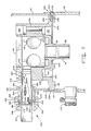
- Figs. 6 and 7 Specific reference will now be made to Figs. 6 and 7 for a more detailed description of the mounting pin assembly of the alternative embodiment, whereby rotational movement of crankcase 46 within housing 12 is prevented.
- mounting flange 52 is axially supported within annular ledge 54.
- the outside diameter of flange 52 is spaced slightly, i.e., .005 - .010 inches, from central portion 16 at annulus 248 to prevent binding when expansion and contraction of the housing occurs due to pressure and temperature conditions.
- a clamping force at 249 is avoided so as to reduce stresses and associated noise.
- a single mounting pin assembly 250 is provided diametrically opposed from a suction fitting assembly 252.
- Mounting pin assembly 250 comprises a radially outwardly opening hole 254 in flange 52.
- An aperture 256 in substantial alignment with hole 254 is provided in central portion 16 of the housing.
- a notched pin 258 is frictionally engaged within hole 254 and extends into aperture 256.
- a connection is made between pin 258 and central portion 16 at aperture 256, represented in Fig. 4 by weldment 260.
- weldment 260 may alternatively comprise brazing material, epoxy, or the like.
- a housing fitting assembly 262 comprising a housing fitting member 264, a removable outer fitting member 266, and a threaded nut 268.
- Housing fitting member 264 is received within an aperture 265 in top portion 14 of the housing, and is sealingly attached thereto as by welding, brazing, soldering, or the like.
- Outer member 266 includes a nipple 270 over which suction tubing of a refrigeration system may be received and brazed or soldered thereto. Threaded nut 268 is rotatable, yet axially retained, on outer fitting member 266.
- Suction fitting assembly 252 further includes a suction tube insert 272 comprising a short length of cylindrical tubing having a first end 274 and a second end 276.
- a ringlike flange 278, such as a washer, is secured to the outside diameter of end 274 and extends radially outwardly therefrom.
- Flange 278 is secured to end 274 by means of brazing or welding.
- Housing fitting assembly 262, and particularly housing member 264 and outer member 266, define a fitting bore 280 in which suction tube insert 272 axially resides. More specifically, the diameter of insert 272 is less than the diameter of bore 280 such that an annular clearance 282 is provided therebetween. In the preferred embodiment, clearance 282 is .050 inches circumferentially about insert 272.
- suction inlet opening 232 and fitting bore 280 will be axially aligned to permit extension of suction tube insert 272 therebetween.
- second end 276 of insert 272 is sealingly slidably engaged within opening 232, as by a slip fit.
- An annular seal 284 is provided in the sidewall of opening 232 so that tube insert 272 may be inserted a selective depth into opening 232 while maintaining a proper seal. In this way, variations in radial spacing between crankcase 46 and central portion 14 of the housing may be compensated for.
- mounting pin assembly 250 provides for a limited degree of rotational alignment. Compensation for misalignment between suction inlet opening 232 and fitting bore 280 along the axial direction with respect to compressor housing 12 is provided by the disclosed structure whereby flange 278 is retained within fitting bore 280. Flange 278 extends radially outwardly from insert 272 and is received between outer fitting member 266 and housing fitting member 264. Furthermore, an annular space 286 is provided between the outside diameter of flange 278 and the inside diameter of threaded nut 268.
- annular space 286 and annular clearance 282 permits random movement of tube insert 272 within bore 280, whereby the axis of insert tube 272 is substantially parallel to and selectively spaced relative to the axis of fitting bore 280.
- This freedom of motion of tube insert 272 within fitting bore 280 translates to approximately .100 inches of compensation for misalignment of suction inlet opening 232 and fitting bore 280 along the vertical axis of the housing.
- Suction fitting 252 provides a sealing arrangement whereby flange 278 is sealingly retained between housing fitting member 264 and outer fitting member 266.
- annular sealing ring 288 is interposed between sealing surface 290 of outer member 266, and flange 278.
- annular sealing ring 292 is interposed between a sealing surface 294 of housing member 264, and flange 278.
- annular sealing rings 288, 292 are retained within grooves in sealing surfaces 290, 294, respectively. Accordingly, flange 278 is sealingly secured between housing fitting member 264 and outer fitting member 266 when threaded nut 268 draws the two members together.
- the disclosed suction fitting assembly further comprises a conical screen filter 296 including a mounting ring 298 at the base end thereof.
- Mounting ring 298 slip fits into a counterbore 300 provided in first end 274 of suction tube insert 272. In such an arrangement, filter 296 may be easily removed for cleaning or replacement.
- Fig. 7 also shows a discharge fitting 302 provided in central portion 16 of housing 12 located directly beneath suction fitting assembly 252.
- the location of discharge fitting 302 in a central or lower portion of the housing provides an advantage in that the fitting acts as a dam and limits to about 20 lbs. the amount of refrigerant charge that will be retained by the compressor and required to be pumped out upon startup.
Landscapes
- Engineering & Computer Science (AREA)
- Mechanical Engineering (AREA)
- General Engineering & Computer Science (AREA)
- Compressor (AREA)
Applications Claiming Priority (2)
| Application Number | Priority Date | Filing Date | Title |
|---|---|---|---|
| US147692 | 1988-01-25 | ||
| US07/147,692 US4846635A (en) | 1988-01-25 | 1988-01-25 | Hermetic compressor mounting pin |
Publications (3)
| Publication Number | Publication Date |
|---|---|
| EP0325694A2 true EP0325694A2 (de) | 1989-08-02 |
| EP0325694A3 EP0325694A3 (en) | 1990-04-18 |
| EP0325694B1 EP0325694B1 (de) | 1992-02-12 |
Family
ID=22522529
Family Applications (1)
| Application Number | Title | Priority Date | Filing Date |
|---|---|---|---|
| EP88116326A Expired - Lifetime EP0325694B1 (de) | 1988-01-25 | 1988-10-03 | Kompressor |
Country Status (7)
| Country | Link |
|---|---|
| US (1) | US4846635A (de) |
| EP (1) | EP0325694B1 (de) |
| JP (1) | JPH0792059B2 (de) |
| AU (1) | AU598165B2 (de) |
| BR (1) | BR8806928A (de) |
| CA (1) | CA1324362C (de) |
| DE (1) | DE3868397D1 (de) |
Cited By (2)
| Publication number | Priority date | Publication date | Assignee | Title |
|---|---|---|---|---|
| EP0507091A1 (de) * | 1991-03-26 | 1992-10-07 | Whirlpool Europe B.V. | Hermetische Motor-Verdichter-Einheit mit verbessertem Motortragegestell oder -Stützträger |
| US10012081B2 (en) | 2015-09-14 | 2018-07-03 | Torad Engineering Llc | Multi-vane impeller device |
Families Citing this family (22)
| Publication number | Priority date | Publication date | Assignee | Title |
|---|---|---|---|---|
| US4842492A (en) * | 1988-01-25 | 1989-06-27 | Tecumseh Products Company | Compressor discharge muffler having cover plate |
| US4934905A (en) * | 1989-04-28 | 1990-06-19 | Tecumseh Products Company | Oil turbulence minimizer for a hermetic compressor |
| US5245960A (en) * | 1992-07-22 | 1993-09-21 | Outboard Marine Corporation | Integral bracket and idler assembly |
| US5405252A (en) * | 1993-01-06 | 1995-04-11 | Nikkanen; Erik | Metering pump |
| US5575629A (en) * | 1994-05-02 | 1996-11-19 | Delaware Capital Formation, Inc. | Vapor control system |
| US5591019A (en) * | 1996-02-28 | 1997-01-07 | Delaware Capital Formation, Inc. | Vapor recovery pump |
| US5752812A (en) * | 1996-02-28 | 1998-05-19 | Delaware Capital Formation, Inc. | Vapor recovery pump |
| US6092996A (en) * | 1997-03-03 | 2000-07-25 | Luk Fahrzeug-Hydraulik Gmbh & Co. Kg | Compressor, particularly for an air conditioning system in a motor vehicle |
| US5984653A (en) | 1997-07-07 | 1999-11-16 | Tecumseh Products Company | Mechanism and method for aligning a fixed scroll in a scroll compressor |
| IT245312Y1 (it) * | 1998-05-28 | 2002-03-20 | Zanussi Elettromecc | Motocompressore ermetico con dispositivi perfezionatidi comando e di controllo |
| DE19925616C1 (de) * | 1999-06-04 | 2000-06-08 | Guenther Engineering Gmbh | Hubkolbenhermetikkompressor |
| JP4153131B2 (ja) * | 1999-09-14 | 2008-09-17 | サンデン株式会社 | 電動圧縮機 |
| US6857366B1 (en) | 1999-11-02 | 2005-02-22 | Erik Nikkanen | Printing press ink transfer mechanism and employment of same |
| US7023167B2 (en) * | 2002-05-02 | 2006-04-04 | Smith Otto J M | Control arrangement for an induction motor compressor having at least three windings, a torque-augmentation circuit a starting capacitor and a resistive element |
| JP2004270614A (ja) * | 2003-03-11 | 2004-09-30 | Sanden Corp | 電動圧縮機 |
| JP2007146736A (ja) * | 2005-11-28 | 2007-06-14 | Sanyo Electric Co Ltd | ロータリコンプレッサ |
| US20080219862A1 (en) * | 2007-03-06 | 2008-09-11 | Lg Electronics Inc. | Compressor |
| US8177536B2 (en) | 2007-09-26 | 2012-05-15 | Kemp Gregory T | Rotary compressor having gate axially movable with respect to rotor |
| TWM472176U (zh) * | 2013-11-07 | 2014-02-11 | Jia Huei Microsystem Refrigeration Co Ltd | 迴轉式壓縮機改良 |
| JP2016148278A (ja) * | 2015-02-12 | 2016-08-18 | カルソニックカンセイ株式会社 | 電動コンプレッサ |
| CN106050621B (zh) * | 2016-07-18 | 2020-01-14 | 珠海格力电器股份有限公司 | 压缩机及其壳体总成 |
| JP6648785B2 (ja) * | 2018-07-11 | 2020-02-14 | 株式会社富士通ゼネラル | 圧縮機 |
Citations (4)
| Publication number | Priority date | Publication date | Assignee | Title |
|---|---|---|---|---|
| US1614676A (en) * | 1922-02-04 | 1927-01-18 | Arthur J Kercher | Refrigerating apparatus |
| US2100799A (en) * | 1934-11-01 | 1937-11-30 | Walter J Sugden | Motor compressor |
| US4470772A (en) * | 1982-05-20 | 1984-09-11 | Tecumseh Products Company | Direct suction radial compressor |
| US4601644A (en) * | 1984-11-13 | 1986-07-22 | Tecumseh Products Company | Main bearing for a rotary compressor |
Family Cites Families (29)
| Publication number | Priority date | Publication date | Assignee | Title |
|---|---|---|---|---|
| US3127092A (en) * | 1964-03-31 | Motor mounting | ||
| US1527162A (en) * | 1921-06-14 | 1925-02-24 | Gray & Davis Corp | Process of making dynamo-electric machines |
| US2130276A (en) * | 1934-10-31 | 1938-09-13 | Gen Motors Corp | Refrigerating apparatus |
| US2178811A (en) * | 1935-11-30 | 1939-11-07 | Westinghouse Electric & Mfg Co | Compression apparatus |
| US2312514A (en) * | 1938-11-03 | 1943-03-02 | Kingston Products Corp | Pump |
| US2369282A (en) * | 1943-02-06 | 1945-02-13 | Curtis Pump Co | Submerged booster pump construction |
| US2439241A (en) * | 1943-02-06 | 1948-04-06 | Curtis Pump Co | Pump assembly |
| US2612843A (en) * | 1946-03-16 | 1952-10-07 | Smith Corp A O | In-line centrifugal pump with fabricated volutes |
| US2575889A (en) * | 1946-03-26 | 1951-11-20 | Rolls Royce | Burner assembly for the combustion chambers of internal-combustion turbines |
| US2517367A (en) * | 1946-09-24 | 1950-08-01 | Winkler Margenthaler Inc | Gas compressor |
| US2465554A (en) * | 1946-10-21 | 1949-03-29 | Roy Maurice | Portable electric air pump |
| US2630964A (en) * | 1949-12-14 | 1953-03-10 | Gen Electric | Compressor mounting |
| US2610993A (en) * | 1951-07-12 | 1952-09-16 | Gen Electric | Adjustable magnetic shunt for permanent magnet generators |
| US2786624A (en) * | 1955-03-24 | 1957-03-26 | Lamb Electric Company | Sub-assembly for electric motor fan unit |
| US3162360A (en) * | 1962-05-14 | 1964-12-22 | Carrier Corp | Compressor venting system |
| US3185099A (en) * | 1963-03-18 | 1965-05-25 | Watts Regulator Co | Motor mounting arrangement for liquid circulator |
| US3539272A (en) * | 1968-12-26 | 1970-11-10 | Laval Turbine California Inc D | Canister pump assembly |
| US3568712A (en) * | 1969-04-01 | 1971-03-09 | Gen Electric | Suction valve for rotary compressor |
| US3853430A (en) * | 1972-08-08 | 1974-12-10 | Trw Inc | Cable-suspended, liner-supported submersible pump installation with locking discharge head |
| US3870440A (en) * | 1974-03-11 | 1975-03-11 | Gen Electric | Hermetically sealed compressor suction tube assembly |
| DK318576A (da) * | 1975-08-04 | 1977-02-05 | Lennox Ind Inc | Indretning til dempning af vibrationer ved kompressorer |
| US4201519A (en) * | 1977-05-03 | 1980-05-06 | Niedermeyer Karl O | Through flow sump pump |
| US4134036A (en) * | 1977-06-03 | 1979-01-09 | Cooper Industries, Inc. | Motor mounting device |
| US4399669A (en) * | 1979-01-29 | 1983-08-23 | Carrier Corporation | Motor compressor unit |
| JPS5910791A (ja) * | 1982-07-08 | 1984-01-20 | Toshiba Corp | 密閉形圧縮機の製造方法 |
| US4547131A (en) * | 1983-07-25 | 1985-10-15 | Copeland Corporation | Refrigeration compressor and method of assembling same |
| US4838769A (en) * | 1988-01-25 | 1989-06-13 | Tecumseh Products Company | High side scotch yoke compressor |
| US4834627A (en) * | 1988-01-25 | 1989-05-30 | Tecumseh Products Co. | Compressor lubrication system including shaft seals |
| US4842492A (en) * | 1988-01-25 | 1989-06-27 | Tecumseh Products Company | Compressor discharge muffler having cover plate |
-
1988
- 1988-01-25 US US07/147,692 patent/US4846635A/en not_active Expired - Lifetime
- 1988-10-03 DE DE8888116326T patent/DE3868397D1/de not_active Expired - Fee Related
- 1988-10-03 EP EP88116326A patent/EP0325694B1/de not_active Expired - Lifetime
- 1988-10-14 CA CA000580211A patent/CA1324362C/en not_active Expired - Fee Related
- 1988-12-07 AU AU26628/88A patent/AU598165B2/en not_active Ceased
- 1988-12-23 JP JP63323782A patent/JPH0792059B2/ja not_active Expired - Fee Related
- 1988-12-28 BR BR888806928A patent/BR8806928A/pt not_active IP Right Cessation
Patent Citations (4)
| Publication number | Priority date | Publication date | Assignee | Title |
|---|---|---|---|---|
| US1614676A (en) * | 1922-02-04 | 1927-01-18 | Arthur J Kercher | Refrigerating apparatus |
| US2100799A (en) * | 1934-11-01 | 1937-11-30 | Walter J Sugden | Motor compressor |
| US4470772A (en) * | 1982-05-20 | 1984-09-11 | Tecumseh Products Company | Direct suction radial compressor |
| US4601644A (en) * | 1984-11-13 | 1986-07-22 | Tecumseh Products Company | Main bearing for a rotary compressor |
Non-Patent Citations (2)
| Title |
|---|
| PATENT ABSTRACTS OF JAPAN, unexamined applications, M field, vol. 11, no. 54, February 19, 1987 THE PATENT OFFICE JAPANESE GOVERNMENT, page 53 M 563 * |
| PATENT ABSTRACTS OF JAPAN, unexamined applications, M field, vol. 8, no. 227, October 18, 1984 THE PATENT OFFICE JAPANESE GOVERNMENT, page 87 M 332 * |
Cited By (2)
| Publication number | Priority date | Publication date | Assignee | Title |
|---|---|---|---|---|
| EP0507091A1 (de) * | 1991-03-26 | 1992-10-07 | Whirlpool Europe B.V. | Hermetische Motor-Verdichter-Einheit mit verbessertem Motortragegestell oder -Stützträger |
| US10012081B2 (en) | 2015-09-14 | 2018-07-03 | Torad Engineering Llc | Multi-vane impeller device |
Also Published As
| Publication number | Publication date |
|---|---|
| DE3868397D1 (de) | 1992-03-26 |
| JPH0792059B2 (ja) | 1995-10-09 |
| JPH02140474A (ja) | 1990-05-30 |
| EP0325694B1 (de) | 1992-02-12 |
| EP0325694A3 (en) | 1990-04-18 |
| BR8806928A (pt) | 1989-08-29 |
| AU2662888A (en) | 1989-08-17 |
| US4846635A (en) | 1989-07-11 |
| AU598165B2 (en) | 1990-06-14 |
| CA1324362C (en) | 1993-11-16 |
Similar Documents
| Publication | Publication Date | Title |
|---|---|---|
| EP0325694B1 (de) | Kompressor | |
| EP0325833B1 (de) | Vertikaler Kompressor mit Kulissenantrieb | |
| EP0325693B1 (de) | Verdichterschmiersystem mit Wellendichtringen | |
| EP0325696B1 (de) | Kompressorventil | |
| EP0325695B1 (de) | Auspuffschalldämpfer mit einer Abdeckplatte für einen Kompressor | |
| EP0386320B1 (de) | Sauganschluss für hermetischen Verdichter | |
| US4601644A (en) | Main bearing for a rotary compressor | |
| EP1469200A2 (de) | Kolbenverdichter | |
| US6135727A (en) | Detachably affixed counterweight and method of assembly | |
| EP0183332B1 (de) | Ansaugrohrdichtung für Rotationsverdichter | |
| EP0386321B1 (de) | Hermetischer Verdichter mit elastischer Innenbefestigung | |
| CA2093768C (en) | Centrifugal oil pump booster | |
| US4844705A (en) | Suction line adaptor and filter for a hermetic compressor | |
| CA2468632C (en) | Compressor crankshaft with bearing sleeve and assembly method |
Legal Events
| Date | Code | Title | Description |
|---|---|---|---|
| PUAI | Public reference made under article 153(3) epc to a published international application that has entered the european phase |
Free format text: ORIGINAL CODE: 0009012 |
|
| AK | Designated contracting states |
Kind code of ref document: A2 Designated state(s): DE FR GB IT |
|
| PUAL | Search report despatched |
Free format text: ORIGINAL CODE: 0009013 |
|
| AK | Designated contracting states |
Kind code of ref document: A3 Designated state(s): DE FR GB IT |
|
| 17P | Request for examination filed |
Effective date: 19900613 |
|
| 17Q | First examination report despatched |
Effective date: 19910410 |
|
| GRAA | (expected) grant |
Free format text: ORIGINAL CODE: 0009210 |
|
| AK | Designated contracting states |
Kind code of ref document: B1 Designated state(s): DE FR GB IT |
|
| PG25 | Lapsed in a contracting state [announced via postgrant information from national office to epo] |
Ref country code: IT Free format text: LAPSE BECAUSE OF FAILURE TO SUBMIT A TRANSLATION OF THE DESCRIPTION OR TO PAY THE FEE WITHIN THE PRE;WARNING: LAPSES OF ITALIAN PATENTS WITH EFFECTIVE DATE BEFORE 2007 MAY HAVE OCCURRED AT ANY TIME BEFORE 2007. THE CORRECT EFFECTIVE DATE MAY BE DIFFERENT FROM THE ONE RECORDED.SCRIBED TIME-LIMIT Effective date: 19920212 |
|
| ET | Fr: translation filed | ||
| REF | Corresponds to: |
Ref document number: 3868397 Country of ref document: DE Date of ref document: 19920326 |
|
| PG25 | Lapsed in a contracting state [announced via postgrant information from national office to epo] |
Ref country code: GB Effective date: 19921003 |
|
| PLBE | No opposition filed within time limit |
Free format text: ORIGINAL CODE: 0009261 |
|
| STAA | Information on the status of an ep patent application or granted ep patent |
Free format text: STATUS: NO OPPOSITION FILED WITHIN TIME LIMIT |
|
| 26N | No opposition filed | ||
| GBPC | Gb: european patent ceased through non-payment of renewal fee |
Effective date: 19921003 |
|
| PG25 | Lapsed in a contracting state [announced via postgrant information from national office to epo] |
Ref country code: DE Effective date: 19930701 |
|
| PGFP | Annual fee paid to national office [announced via postgrant information from national office to epo] |
Ref country code: FR Payment date: 20030915 Year of fee payment: 16 |
|
| PG25 | Lapsed in a contracting state [announced via postgrant information from national office to epo] |
Ref country code: FR Free format text: LAPSE BECAUSE OF NON-PAYMENT OF DUE FEES Effective date: 20050630 |
|
| REG | Reference to a national code |
Ref country code: FR Ref legal event code: ST |