EP0325521A1 - Automatic balancing device for a centrifuge in operation - Google Patents
Automatic balancing device for a centrifuge in operation Download PDFInfo
- Publication number
- EP0325521A1 EP0325521A1 EP89400125A EP89400125A EP0325521A1 EP 0325521 A1 EP0325521 A1 EP 0325521A1 EP 89400125 A EP89400125 A EP 89400125A EP 89400125 A EP89400125 A EP 89400125A EP 0325521 A1 EP0325521 A1 EP 0325521A1
- Authority
- EP
- European Patent Office
- Prior art keywords
- imbalance
- signals
- mass
- inputs
- circuit
- Prior art date
- Legal status (The legal status is an assumption and is not a legal conclusion. Google has not performed a legal analysis and makes no representation as to the accuracy of the status listed.)
- Granted
Links
Images


Classifications
-
- G—PHYSICS
- G09—EDUCATION; CRYPTOGRAPHY; DISPLAY; ADVERTISING; SEALS
- G09B—EDUCATIONAL OR DEMONSTRATION APPLIANCES; APPLIANCES FOR TEACHING, OR COMMUNICATING WITH, THE BLIND, DEAF OR MUTE; MODELS; PLANETARIA; GLOBES; MAPS; DIAGRAMS
- G09B9/00—Simulators for teaching or training purposes
- G09B9/02—Simulators for teaching or training purposes for teaching control of vehicles or other craft
-
- B—PERFORMING OPERATIONS; TRANSPORTING
- B64—AIRCRAFT; AVIATION; COSMONAUTICS
- B64G—COSMONAUTICS; VEHICLES OR EQUIPMENT THEREFOR
- B64G7/00—Simulating cosmonautic conditions, e.g. for conditioning crews
-
- G—PHYSICS
- G01—MEASURING; TESTING
- G01M—TESTING STATIC OR DYNAMIC BALANCE OF MACHINES OR STRUCTURES; TESTING OF STRUCTURES OR APPARATUS, NOT OTHERWISE PROVIDED FOR
- G01M1/00—Testing static or dynamic balance of machines or structures
- G01M1/30—Compensating unbalance
- G01M1/36—Compensating unbalance by adjusting position of masses built-in the body to be tested
- G01M1/365—Compensating unbalance by adjusting position of masses built-in the body to be tested using balancing liquid
-
- G—PHYSICS
- G01—MEASURING; TESTING
- G01N—INVESTIGATING OR ANALYSING MATERIALS BY DETERMINING THEIR CHEMICAL OR PHYSICAL PROPERTIES
- G01N3/00—Investigating strength properties of solid materials by application of mechanical stress
- G01N3/08—Investigating strength properties of solid materials by application of mechanical stress by applying steady tensile or compressive forces
- G01N3/16—Investigating strength properties of solid materials by application of mechanical stress by applying steady tensile or compressive forces applied through gearing
- G01N3/165—Investigating strength properties of solid materials by application of mechanical stress by applying steady tensile or compressive forces applied through gearing generated by rotation, i.e. centrifugal force
-
- Y—GENERAL TAGGING OF NEW TECHNOLOGICAL DEVELOPMENTS; GENERAL TAGGING OF CROSS-SECTIONAL TECHNOLOGIES SPANNING OVER SEVERAL SECTIONS OF THE IPC; TECHNICAL SUBJECTS COVERED BY FORMER USPC CROSS-REFERENCE ART COLLECTIONS [XRACs] AND DIGESTS
- Y10—TECHNICAL SUBJECTS COVERED BY FORMER USPC
- Y10T—TECHNICAL SUBJECTS COVERED BY FORMER US CLASSIFICATION
- Y10T74/00—Machine element or mechanism
- Y10T74/21—Elements
- Y10T74/2109—Balancing for drum, e.g., washing machine or arm-type structure, etc., centrifuge, etc.
Definitions
- the present invention relates to an automatic balancing device of a centrifuge in operation comprising a rotating arm comprising at least one horizontal tube mounted on a turret driven in rotation about a vertical axis relative to a frame.
- Centrifuges are used in many fields and in particular as geotechnical centrifuges for industrial or research work.
- stresses to which structures may be subjected for example under the effect of earthquakes, are simulated using a centrifuge, and a certain number of data are obtained from tests carried out on a model. or reduced scale prototype which is placed in a pendulum basket suspended at the end of the rotating arm of the centrifuge.
- a certain number of measurements are performed on reduced models of structures to determine mathematical models representing the behavior of structures.
- the tests are often conducted until the structure placed in the centrifuge basket breaks. A large imbalance then occurs suddenly on the centrifuge.
- the rebalancing operations after rupture of the model impose the stopping of the centrifuge, in order to act on the mass or the location of the counterweights generally placed on the rotating arm opposite the nacelle carrying the model subjected to mechanical resistance tests . These rebalancing operations are long.
- the sudden imbalance created when a model ruptures can even cause damage to the centrifuge, which delays further testing. It should be noted that significant imbalances may occur during the tests, although the failure of the model tested was not achieved. This is for example the case during tests of structures cooperating with fluctuating masses of liquid, in particular during tests of structures of dams or dikes.
- the present invention aims to remedy the aforementioned drawbacks and to make it possible to detect and automatically compensate, in a simple and effective manner and without requiring the stopping of the centrifuge, the unbalance liable to appear in a centrifuge in operation.
- an automatic balancing device of a centrifuge in operation comprising a rotating arm comprising at least one horizontal tube mounted on a turret driven in rotation about a vertical axis with respect to a frame, characterized in that that it comprises a system for selective displacement of a mass of fluid inside said hollow horizontal tube and a device for measuring the imbalance of the rotating arm capable of having an unbalance and in that the device for measuring imbalance comprises sensors arranged on the centrifuge, circuits for processing the signals delivered by the sensors to deliver alarm or rebalancing control signals in the event of imbalance detection, and means for controlling said system for selective movement of a mass of fluid, said control means reacting to the rebalancing control signals delivered by the imbalance measuring device to cause r in real time a selective movement, inside said hollow horizontal tube, of a mass of fluid ensuring dynamic balancing of the rotating arm of the centrifuge.
- the sensors comprise four bridges of strain gauges arranged on elastic parts incorporated in the frame or in the frame-foundation link, the four bridges of gauges being arranged in a horizontal plane at equal distance from the axis. vertical rotation of the rotating arm and diametrically opposite two by two in two directions orthogonal to each other.
- the imbalance measurement device includes a circuit for shaping the signals from the gauge bridges, a set of four pairs of sampler-blockers connected so as to memorize the maximums and minimums of the voltages from each of the setting circuits form of the signals delivered by the four gauge bridges, first four summing circuits with two inputs to each receive the signals coming from the two sample-and-hold units having recorded a maximum and a minimum of voltage coming from the same shaping circuit, and to determine the absolute value of the difference between said maximum and minimum voltage, a first four-input summing circuit for receiving the signals from said first four two-input summing circuits, and to determine the average value of the differences between the signals from the first four summing circuits and circuits for using the signals from the first four summing circuit re inputs to deliver the information representative of the level of imbalance of the rotating arm to display and control members of the system for selective displacement of a mass of fluid inside said hollow horizontal tube in order to reduce if necessary the level of imbalance of the rotating arm.
- the system for selective displacement of a mass of fluid inside said hollow horizontal tube comprises a jack with a free piston having two end end faces delimiting inside from the hollow cylinder two end chambers, means for filling the free space with oil located between the front faces of the free piston as well as end chambers, an oil tank and a hydraulic pump, and a circuit d oil evacuation located in one or other of the end chambers, which evacuation circuit is provided with servovalves controlled by the control signals from the imbalance measurement device.
- the system for selective displacement of a mass of fluid to the interior of the hollow horizontal tube comprises a pair of flexible membranes arranged inside the hollow tube and tightly attached to the side wall of the hollow tube in two radial planes spaced from the ends of said tube, means for filling with liquid fluid free space between the membranes, a device for supplying gaseous fluid under pressure, and a circuit for selective connection between the device for supplying gaseous fluid under pressure and each of the variable volume chambers located between the flexible membranes and the ends of the hollow tube, which selective connection circuit comprises servovalves controlled by the control signals from the device for measuring the imbalance.
- the system for selective displacement of a mass of fluid inside the hollow horizontal tube comprises first and second chambers delimited by fixed walls and separated from each other by a wall fixed transverse which includes the axis of rotation of the turret, means for filling with liquid fluid in one of the chambers, conduits for placing the two chambers in communication with one another, a device for supplying fluid pressurized gas and a selective connection circuit between the pressurized gaseous fluid supply device and each of the chambers, which selective connection circuit comprises servovalves controlled by the control signals from the imbalance measurement device.
- control of the system for selective movement of a mass of fluid inside the hollow horizontal tube is disengageable from the imbalance measurement device when the rotating arm of the centrifuge rotates at low speed, the balancing mass being maintained in neutral position.
- the invention also applies to a centrifuge comprising a rotating arm composed of two parallel hollow tubes which are each equipped with a system for selective displacement of a mass of fluid inside the bore of the corresponding tube, each systems for selective displacement of a mass of fluid being controlled from a common imbalance measurement device.
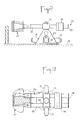
- FIGS. 2 and 3 A centrifuge more particularly suited to geotechnical applications and to which the invention is applicable is shown in FIGS. 2 and 3.
- Such a centrifuge conventionally comprises a frame 23 which is advantageously of pyramidal or frustoconical shape and the base of which is anchored in foundations 29.
- Electric motors 21 cooperating with a reduction gear 22 ensure the rotation drive of a turret 24 on which is mounted a rotating arm 20, one end of which can be fitted with a tilting nacelle 27 while the part of the rotating arm 20 situated on the other side of the turret relative to the nacelle 27 carries counterweights 26.
- the rotating arm comprises at least one, and preferably two bored tubes 25 closed at their ends.
- the steel tubes 25 comprise a borehole which extends almost to the end carrying the nacelle 27 (FIG. 1) and the end opposite the nacelle is closed by a plate 28.
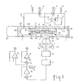
- FIG. 1 A first embodiment of the automatic balancing device according to the invention is shown in Figure 1 which shows in axial section a tube 25 of the rotating arm 20.
- the hollow horizontal tube 25 which is mounted on the turret 24 and carries a from its ends the pivoting nacelle 27 defines a rectified cylinder 29 inside which can move a free piston 6 having two end end faces 61, 62 defining inside the cylinder 29 two chambers the end 69, 70 with respectively the end of the tube carrying the nacelle 27 and the closure plate 28.
- the piston 6 has a central section of section smaller than that of the end end faces 61, 62 in order to define with the cylinder 29 an annular free space.
- Purge means 1 are arranged in the lower part of the wall of the hollow tube 25 in order to allow a purge of each of the end chambers 69, 70 as well as of the central annular space.
- a hydraulic pump 31, capable of creating pressures for example of the order of 200.105 Pa and an oil tank 3 are connected respectively by a line 17 and a tank line 16 to two servovalves 4 with proportional action of the type 5 / 2 controlled by the control signals from the imbalance measuring device which will be described later.
- Each of the servovalves 4 is connected to an end chamber 69, 70 respectively, by a line 15.
- Valves 5 of the 2/2 type disposed on each of the lines 15 allow the venting and evacuation of the oil, so that the traps 1 can ultimately be eliminated.
- the hydraulic pump 31, the hydraulic tank 3 and the servovalves 4 are arranged in the central part of the rotating arm 20 of the centrifuge in a zone of weak constraints and cannot disturb the operation of the centrifuge.
- the balancing device according to the invention can compensate for unbalance in a very large range of values, of the order of ⁇ 20,000 N with a very limited reaction time, of the order of 2 minutes to regain the initial balance. .
- the precision of the balancing device is itself very high since at accelerations of the order of ten times the g value of imbalances of ⁇ 1 kg can be detected.
- Magnetic type detectors can be used to center the piston when stationary.
- two parallel hollow tubes 25 can each be equipped with a system for selective displacement of a mass of fluid inside the corresponding tube, such as the hydraulic piston system which has just been described. , each of the selective displacement systems being controlled from a common device for measuring imbalance. It is however also possible, in the case of two parallel tubes 25 each equipped with an imbalance compensation system, to combine the compensation actions in a specific manner for example to cause the center of mass to move in a plane outside the axis of rotation of the machine.
- the imbalance compensation device is disengaged up to accelerations, for example of the order of 10 g, and the small imbalance detected then using the unbalance measurement device makes it possible to determine whether the counterweights are positioned or not so as to balancing at the rotational speeds corresponding to higher working accelerations, for example of the order of 100 g.
- the imbalance measurement device includes sensors which can for example be of the accelerometric or capacitive type and allow, after signal processing, to issue alarm or rebalancing control signals in the event of imbalance detection.
- the servovalves 4 controlling the system for selective displacement of the hydraulic fluid react to the rebalancing control signals delivered by the measuring device to cause in real time a selective displacement of hydraulic fluid inside the hollow tube or tubes 25 in a direction which tends to ensure dynamic balancing of the rotating arm of the centrifuge.
- the sensors 7 of the imbalance measurement device include four bridges of strain gauges arranged on elastic parts incorporated in the frame 23 or in the frame link 23 - foundation 29.
- the four gauge bridges 7 are arranged in a horizontal plane equidistant from the vertical axis of rotation of the rotary arm 20 and diametrically opposite two by two in two directions orthogonal to each other.
- the positions of the four gauge bridges 7 are identified by the letters A, B, C, D in FIG. 7. The implementation of this type of sensor will be explained below.
- the particularity of the arm of a rotating centrifuge, even if it is equipped with a pendulum basket, is to have its mass concentrated in a volume of low height, which it is possible to assimilate in plan.
- the arm is symmetrical in construction and its mass is preponderant in front of the on-board mass, which has the consequence to position the combined center of mass on the axis of symmetry of the arm or very close to it, whatever the position of the center of mass of the load.
- the unbalance measurement device using strain gauges located in a plane and the associated balancing system take these characteristics into account without, however, eliminating the possibility of being applied to more complex cases.
- the forces generated in the frame 23 by the rotation of an unbalanced arm rotating at constant speed are sinusoidal.
- phase of this sinusoidal force related to the reference axes of the frame depends on the instantaneous position of the unbalance relative to this frame and, consequently, depends on the position of the rotating arm.
- the rotating arm 20 comprising two hollow tubes 25 is shown in its original position, the axis of the arm 20 passing through the center of rotation O and the center of mass M of the nacelle 27 being coincident with l axis from which the angular positions are identified.
- Points A, B, C, D located in positions 90 °, 180 °, 270 ° and 0 ° respectively on the frame 23 represent the geometric position of the gauge bridges 7.
- the shape of the voltage signals delivered by the gauge bridges 7 located at points A, B, C, D, as a function of the angular position ⁇ of the rotating arm 20, and therefore as a function of time, is represented by the curves ABCD of the Figures 6A, 6B, 6C, 6D.
- the electrical signals supplied by the strain gauges 7 after amplification are proportional and in phase with the resulting forces of the unbalance.
- the measurement device associated with the sensors 7 has been shown schematically in FIGS. 1, 4 and 5 with a module 8 for signal shaping, a demodulation module 9, an amplification stage 10, a set 11 d display measured imbalances and amplifiers 12 delivering error signals a and b to the servovalves 4 to control the operation of the imbalance compensation device, that is to say the displacement of the hydraulic fluid from an end chamber 69 or 70 to the other 70 or 69.
- the references 13 and 14 designate summing circuits allowing the application of feedback signals.
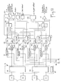
- FIG. 9 shows in more detail an embodiment of the device for measuring imbalance associated with the sensors 7.
- the measurement device of FIG. 9 comprises a circuit 8 for shaping the signals coming from the gauge bridges 7.
- This circuit 8 constitutes a dynamic conditioner provided with a power supply 80 and comprising two pairs 81, 82 of preamplifiers with compensation for zero located near the strain gauges 7.
- Four pairs of sampler-blockers 91, 95; 92, 96; 93, 97; 94, 98 are provided for recording the maximums and minimums of the voltages from each of the shaping circuits associated with the gauge bridges 7.
- the control of the sampler-blockers is carried out on the basis of all-or-nothing signals generated by the position coding of the rotating arm 20.
- These four signals ⁇ A, ⁇ B, ⁇ C, ⁇ D are offset by 90 degrees between them and are arranged in such a way that the sampler-locks store the maximums and minimums of the voltages from the amplifiers 81, 82.
- Four summing circuits with two inputs 191 to 194 each receive the signals from the two sample-and-hold circuits 91 and 95; 92 and 96; 93 and 97; 94 and 98 having recorded a maximum and a minimum of voltage coming from the same shaping circuit, and deliver signals corresponding to the absolute values of the differences between said maximum and minimum of voltage, designated by ⁇ A, ⁇ B, ⁇ C, and ⁇ D for the sensors located at points A, B, C, D in Figure 7.
- a four-input summing circuit 99 receives the signals from the four two-input summers 191 to 194 and determine the average value ⁇ deviations ⁇ A, ⁇ B, ⁇ C, ⁇ D constituted by the signals from the summing circuits with two inputs 191 to 194.
- circuits 111, 113, 114, 115 use the signals ⁇ from the summing circuit with four inputs 99 for delivering the information representative of the level of imbalance of the rotating arm to display members and to the servovalves 4 for controlling the system for selective displacement of a mass of fluid inside a hollow horizontal tube 25 to reduce when necessary the level of imbalance of the rotating arm 20 of the centrifuge.
- the circuit 111 constitutes an amplification chain which can be connected to a display member constituting an analog indicator of the dynamic unbalance.
- the signals from the chain 111 can be used on a line 130 as verification signals for the balancing device.
- threshold circuits 113, 114 are connected to the output of the summing circuit 99 to determine two levels of imbalance beyond which an alarm or a control of the servovalves 4 is carried out by means of relays, not shown in the drawing. .
- the circuit 115 consists of an analog-converter which converts the measured values into digital form for the purpose of a digital display and for processing the measurement results using a computer associated with the measurement device and rebalancing control.
- the imbalance measurement device further comprises four comparator circuits 131 to 134 arranged between the output of the summing circuit with four inputs 99 and respectively each of the inputs of this summing circuit 99.
- the outputs of the comparator circuits 131 to 134 are connected to a circuit with fault detection threshold 135 which delivers information representative of a fault when the output signal from one of the comparators 131 to 134 exceeds a predetermined value, for example if the difference in the output voltage of one of the chains versus value average exceeds 10% of this, which corresponds to a defect in one of the measurement chains. It is thus possible to trigger an alarm in the event of a failure of an extensometry bridge or of its amplification chain. This security is very important in the case of a centrifuge where the failure to detect a real imbalance can have dramatic consequences.
- the imbalance measurement device which has just been described eliminates static errors and temperature drifts. However, it is often useful to know the static force applied to the frame.
- the imbalance measurement device comprises four second summing circuits with two inputs 195 to 198 which each receive the signals from two sampler-blockers 91, 95; 92, 96; 93, 97; 94, 98 having recorded a maximum and a minimum of voltage from the same shaping circuit (U AM and U Am ; U BM and U Bm ; U CM and U cm ; U DM and U Dm ).
- These summing circuits 195 to 198 each determine the sum respectively ⁇ A, ⁇ B, ⁇ C, ⁇ D of said maximum and minimum voltage which are applied to them.
- a second summing circuit with four inputs 199 receives the signals ⁇ A, ⁇ B, ⁇ C, ⁇ D from the four second summing circuits with two inputs 195 to 198 and determines the average values ⁇ signals from the four summers 195 to 198.
- An output amplifier 112 is connected to the output of the summing circuit 199 and delivers to an analog indicator information representative of the static force applied to the frame 23 by the rotating arm 20. This information representing the static load of the frame can be used for example to measure the mass of the specimen on board the nacelle 27.
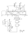
- FIGS. 4 and 5 two other embodiments of a system for selective displacement of a mass of fluid inside one or more hollow horizontal tubes 25 incorporated in the rotating arm 20.
- the modes of embodiment of FIGS. 4 and 5 can use, like the embodiment of FIG. 1, the imbalance detection device which has just been described, and comprise a pair of control servovalves 104 respectively 204 controlled from the unbalance measuring device and playing a role similar to that of the servovalves 4 of the embodiment of FIG. 1.
- the rebalancing is obtained exclusively by the displacement of a mass of hydraulic fluid and no free piston is used any more.
- a pair 106 of flexible membranes 161, 162 are arranged inside the bore 29 of the hollow tube 25 and are tightly attached to the side wall of the hollow tube 25 in two radial planes located at a certain distance from the ends of the bore 29 so as to provide in the bore 29 two chambers on either side of a central chamber 105 delimited by the two flexible membranes 161, 162 and the wall of the bore 29.
- a hydraulic fluid is introduced into the central chamber 105 through an orifice 2.
- Ports 1 for purging the various compartments defined inside the hollow tube 25 are also provided.
- An air compressor 103 for example at 200.105 Pa, or a pressurized air tank, is connected by outlet lines 17 and return 16 to the servovalves 104, themselves connected by lines 15 to the two chambers with variable volume situated between the flexible membranes 161, 162 and the ends of the hollow tube 25.
- signals a and b are applied to the servovalves 104 to apply pressurized air in either of the two end chambers so to allow, thanks to the flexible membranes 161, 162 a displacement of the mass of liquid located in the central chamber 105 and thus contribute to effect in real time a rebalancing of the rotating arm 20 of the centrifuge.
- Figure 5 is similar to that of Figure 4 in that it also allows to cause from compressed air, the movement of a mass of liquid used to rebalance the arm of a centrifuge.
- flexible membranes are not used, but the hollow tube 25 defines two chambers 261, 262 delimited by fixed walls and separated from each other by a fixed transverse wall which includes the axis of rotation of the turret.
- Means 2 for filling with liquid fluid in one of the chambers, for example the chamber 261, are provided in the side wall of the hollow tube 25, and purge means 1 are provided in the bottom wall of each of the chambers 261, 262.
- a line 206 further ensures the communication of the two chambers 261, 262 with each other.
- a device 203 for supplying compressed air or another gaseous fluid under pressure can be selectively connected by servovalves 204 controlled from the imbalance measurement device, and through conduits 15 to one or the other. of rooms 261, 262.
- FIG. 5 shows the case where the liquid fluid 205 initially in the chamber 261 has been expelled by the conduit 206 towards the second chamber 262 after application of compressed air in the chamber 261 from the compressed air reservoir 203 and through the servovalve 204 controlled by the control signals a delivered by the electronic device for measuring imbalance.
- the hollow tubes 25 to which the dynamic balancing system according to the invention is applied may preexist in the rotating arm of the centrifuge as support elements or be attached to the rotating arm in order to specifically produce the balancing function.
- the hollow tubes 25 bored and lapped be produced In high quality steel.
- the mounting of a free piston such as the piston 6 of Figure 1 is however relatively easy so that the adaptation of a balancing system according to the invention to rotating arms of centrifuges already equipped with hollow tubes of high quality is particularly simple and economical.
Abstract
Description
La présente invention a pour objet un dispositif d'équilibrage automatique d'une centrifugeuse en fonctionnement comprenant un bras tournant comportant au moins un tube horizontal monté sur une tourelle entraînée en rotation autour d'un axe vertical par rapport à un bâti.The present invention relates to an automatic balancing device of a centrifuge in operation comprising a rotating arm comprising at least one horizontal tube mounted on a turret driven in rotation about a vertical axis relative to a frame.
Les centrifugeuses sont utilisées dans de nombreux domaines et notamment en tant que centrifugeuses géotechniques pour des travaux industriels ou de recherche. Dans ce cas, on simule à l'aide d'une centrifugeuse des contraintes auxquelles peuvent être soumises des structures, par exemple sous l'effet de secousses sismiques, et on relève un certain nombre de données à partir d'essais effectués sur un modèle ou prototype à échelle réduite qui est placé dans une nacelle pendulaire suspendue à l'extrémité du bras tournant de la centrifugeuse. Lors d'essais au cours desquels les modèles de structures sont soumis à des efforts croissants ou alternés à l'aide de l'entraînement en rotation du bras tournant de la centrifugeuse à des vitesses de rotation ou en cycles alternés, un certain nombre de mesures sont effectuées sur les modèles réduits de structures afin de déterminer des modèles mathématiques représentant le comportement des structures.Centrifuges are used in many fields and in particular as geotechnical centrifuges for industrial or research work. In this case, stresses to which structures may be subjected, for example under the effect of earthquakes, are simulated using a centrifuge, and a certain number of data are obtained from tests carried out on a model. or reduced scale prototype which is placed in a pendulum basket suspended at the end of the rotating arm of the centrifuge. During tests in which the structural models are subjected to increasing or alternating forces using the rotary drive of the rotating arm of the centrifuge at rotational speeds or in alternating cycles, a certain number of measurements are performed on reduced models of structures to determine mathematical models representing the behavior of structures.
Les essais sont souvent conduits jusqu'à la rupture de la structure placée dans la nacelle de la centrifugeuse. Il se produit alors de façon brutale un déséquilibre important sur la centrifugeuse. Les opérations de rééquilibrage après rupture du modèle imposent l'arrêt de la centrifugeuse, afin d'agir sur la masse ou l'emplacement des contrepoids généralement placés sur le bras tournant de façon opposée à la nacelle portant le modèle soumis aux essais de résistance mécanique. Ces opérations de rééquilibrage sont longues. Parfois, le brusque déséquilibre créé à la rupture d'un modèle peut même provoquer un endommagement de la centrifugeuse qui retarde la poursuite des essais. On notera que des déséquilibres importants peuvent se produire lors des essais, bien que l'on ne soit pas parvenu à la rupture du modèle testé. C'est par exemple le cas lors d'essais de structures coopérant avec des masses de liquide fluctuantes, notamment lors d'essais de structures de barrages ou digues.The tests are often conducted until the structure placed in the centrifuge basket breaks. A large imbalance then occurs suddenly on the centrifuge. The rebalancing operations after rupture of the model impose the stopping of the centrifuge, in order to act on the mass or the location of the counterweights generally placed on the rotating arm opposite the nacelle carrying the model subjected to mechanical resistance tests . These rebalancing operations are long. Sometimes the sudden imbalance created when a model ruptures can even cause damage to the centrifuge, which delays further testing. It should be noted that significant imbalances may occur during the tests, although the failure of the model tested was not achieved. This is for example the case during tests of structures cooperating with fluctuating masses of liquid, in particular during tests of structures of dams or dikes.
La présente invention vise à remédier aux inconvénients précités et à permettre de détecter et de compenser automatiquement, de manière simple et efficace et sans imposer l'arrêt de la centrifugeuse, le balourd susceptible d'apparaître dans une centrifugeuse en fonctionnement.The present invention aims to remedy the aforementioned drawbacks and to make it possible to detect and automatically compensate, in a simple and effective manner and without requiring the stopping of the centrifuge, the unbalance liable to appear in a centrifuge in operation.
Ces buts sont atteints grâce à un dispositif d'équilibrage automatique d'une centrifugeuse en fonctionnement comprenant un bras tournant comportant au moins un tube horizontal monté sur une tourelle entraînée en rotation autour d'un axe vertical par rapport à un bâti, caractérisé en ce qu'il comprend un système de déplacement sélectif d'une masse de fluide à l'intérieur dudit tube horizontal creux et un dispositif de mesure du déséquilibre du bras tournant susceptible de présenter un balourd et en ce que le dispositif de mesure de déséquilibre comprend des capteurs disposés sur la centrifugeuse, des circuits de traitement des signaux délivrés par les capteurs pour délivrer des signaux d'alarme ou de commande de rééquilibrage en cas de détection de balourd, et des moyens de commande dudit système de déplacement sélectif d'une masse de fluide, lesdits moyens de commande réagissant aux signaux de commande de rééquilibrage délivrés par le dispositif de mesure de déséquilibre pour provoquer en temps réel un déplacement sélectif, à l'intérieur dudit tube horizontal creux, d'une masse de fluide assurant un équilibrage dynamique du bras tournant de la centrifugeuse.These goals are achieved by an automatic balancing device of a centrifuge in operation comprising a rotating arm comprising at least one horizontal tube mounted on a turret driven in rotation about a vertical axis with respect to a frame, characterized in that that it comprises a system for selective displacement of a mass of fluid inside said hollow horizontal tube and a device for measuring the imbalance of the rotating arm capable of having an unbalance and in that the device for measuring imbalance comprises sensors arranged on the centrifuge, circuits for processing the signals delivered by the sensors to deliver alarm or rebalancing control signals in the event of imbalance detection, and means for controlling said system for selective movement of a mass of fluid, said control means reacting to the rebalancing control signals delivered by the imbalance measuring device to cause r in real time a selective movement, inside said hollow horizontal tube, of a mass of fluid ensuring dynamic balancing of the rotating arm of the centrifuge.
De façon plus particulière, les capteurs comprennent quatre ponts de jauges d'extensométrie disposés sur des pièces élastiques incorporées dans le bâti ou dans la liaison bâti-fondation, les quatre ponts de jauges étant disposés dans un plan horizontal à égale distance de l'axe vertical de rotation du bras tournant et diamétralement opposés deux à deux selon deux directions orthogonales entre elles.More particularly, the sensors comprise four bridges of strain gauges arranged on elastic parts incorporated in the frame or in the frame-foundation link, the four bridges of gauges being arranged in a horizontal plane at equal distance from the axis. vertical rotation of the rotating arm and diametrically opposite two by two in two directions orthogonal to each other.
Selon une caractéristique avantageuse de l'invention, le dispositif de mesure de déséquilibre comprend un circuit de mise en forme des signaux issus des ponts de jauges, un ensemble de quatre couples d'échantillonneurs-bloqueurs connectés de manière à mémoriser les maximums et les minimums des tensions issues de chacun des circuits de mise en forme des signaux délivrés par les quatre ponts de jauges, quatre premiers circuits sommateurs à deux entrées pour recevoir chacun les signaux issus des deux échantillonneurs-bloqueurs ayant enregistré un maximum et un minimum de tension issus d'un même circuit de mise en forme, et pour déterminer la valeur absolue de la différence entre lesdits maximum et minimum de tension, un premier circuit sommateur à quatre entrées pour recevoir les signaux issus desdits quatre premiers circuits sommateurs à deux entrées, et pour déterminer la valeur moyenne des écarts entre les signaux issus des quatre premiers circuits sommateurs et des circuits d'utilisation des signaux issus du premier circuit sommateur à quatre entrées pour délivrer les informations représentatives du niveau de déséquilibre du bras tournant à des organes d'affichage et de commande du système de déplacement sélectif d'une masse de fluide à l'intérieur dudit tube horizontal creux en vue de réduire en cas de besoin le niveau de déséquilibre du bras tournant.According to an advantageous characteristic of the invention, the imbalance measurement device includes a circuit for shaping the signals from the gauge bridges, a set of four pairs of sampler-blockers connected so as to memorize the maximums and minimums of the voltages from each of the setting circuits form of the signals delivered by the four gauge bridges, first four summing circuits with two inputs to each receive the signals coming from the two sample-and-hold units having recorded a maximum and a minimum of voltage coming from the same shaping circuit, and to determine the absolute value of the difference between said maximum and minimum voltage, a first four-input summing circuit for receiving the signals from said first four two-input summing circuits, and to determine the average value of the differences between the signals from the first four summing circuits and circuits for using the signals from the first four summing circuit re inputs to deliver the information representative of the level of imbalance of the rotating arm to display and control members of the system for selective displacement of a mass of fluid inside said hollow horizontal tube in order to reduce if necessary the level of imbalance of the rotating arm.
Conformément à un premier mode de réalisation de l'invention, le système de déplacement sélectif d'une masse de fluide à l'intérieur dudit tube horizontal creux comprend un vérin avec un piston libre présentant deux faces frontales d'extrémité délimitant à l'intérieur du cylindre creux deux chambres d'extrémité, des moyens de remplissage en huile de l'espace libre situé entre les faces frontales du piston libre ainsi que des chambres d'extrémité, un réservoir d'huile et une pompe hydraulique, et un circuit d'évacuation de l'huile située dans l'une ou l'autre des chambres d'extrémité, lequel circuit d'évacuation est muni de servovalves commandées par les signaux de commande issus du dispositif de mesure de déséquilibre.According to a first embodiment of the invention, the system for selective displacement of a mass of fluid inside said hollow horizontal tube comprises a jack with a free piston having two end end faces delimiting inside from the hollow cylinder two end chambers, means for filling the free space with oil located between the front faces of the free piston as well as end chambers, an oil tank and a hydraulic pump, and a circuit d oil evacuation located in one or other of the end chambers, which evacuation circuit is provided with servovalves controlled by the control signals from the imbalance measurement device.
Selon un second mode de réalisation de l'invention, le système de déplacement sélectif d'une masse de fluide à l'intérieur du tube horizontal creux comprend une paire de membranes flexibles disposées à l'intérieur du tube creux et rattachées de façon étanche à la paroi latérale du tube creux selon deux plans radiaux écartés des extrémités dudit tube, des moyens de remplissage en fluide liquide de l'espace libre compris entre les membranes, un dispositif de fourniture de fluide gazeux sous pression, et un circuit de liaison sélective entre le dispositif de fourniture de fluide gazeux sous pression et chacune des chambres à volume variable situées entre les membranes flexibles et les extrémités du tube creux, lequel circuit de liaison sélective comprend des servovalves commandés par les signaux de command issus du dispositif de mesure du déséquilibre.According to a second embodiment of the invention, the system for selective displacement of a mass of fluid to the interior of the hollow horizontal tube comprises a pair of flexible membranes arranged inside the hollow tube and tightly attached to the side wall of the hollow tube in two radial planes spaced from the ends of said tube, means for filling with liquid fluid free space between the membranes, a device for supplying gaseous fluid under pressure, and a circuit for selective connection between the device for supplying gaseous fluid under pressure and each of the variable volume chambers located between the flexible membranes and the ends of the hollow tube, which selective connection circuit comprises servovalves controlled by the control signals from the device for measuring the imbalance.
Selon encore un autre mode de réalisation, le système de déplacement sélectif d'une masse de fluide à l'intérieur du tube horizontal creux comprend des première et seconde chambres délimitées par des parois fixes et séparées l'une de l'autre par une paroi transversale fixe qui inclut l'axe de rotation de la tourelle, des moyens de remplissage en fluide liquide de l'une des chambres, des conduits de mise en communication des deux chambres l'une avec l'autre, un dispositif de fourniture de fluide gazeux sous pression et un circuit de liaison sélective entre le dispositif de fourniture de fluide gazeux sous pression et chacune des chambres, lequel circuit de liaison sélective comprend des servovalves commandés par les signaux de commande issus du dispositif de mesure de déséquilibre.According to yet another embodiment, the system for selective displacement of a mass of fluid inside the hollow horizontal tube comprises first and second chambers delimited by fixed walls and separated from each other by a wall fixed transverse which includes the axis of rotation of the turret, means for filling with liquid fluid in one of the chambers, conduits for placing the two chambers in communication with one another, a device for supplying fluid pressurized gas and a selective connection circuit between the pressurized gaseous fluid supply device and each of the chambers, which selective connection circuit comprises servovalves controlled by the control signals from the imbalance measurement device.
Avantageusement, la commande du système de déplacement sélectif d'une masse de fluide à l'intérieur du tube horizontal creux est débrayable du dispositif de mesure de déséquilibre lorsque le bras tournant de la centrifugeuse tourne à faible vitesse, la masse d'équilibrage étant maintenue en position neutre.Advantageously, the control of the system for selective movement of a mass of fluid inside the hollow horizontal tube is disengageable from the imbalance measurement device when the rotating arm of the centrifuge rotates at low speed, the balancing mass being maintained in neutral position.
L'invention s'applique également à une centrifugeuse comportant un bras tournant composé de deux tubes creux parallèles qui sont équipés chacun d'un système de déplacement sélectif d'une masse de fluide à l'intérieur de l'alésage du tube correspondant, chacun des systèmes de déplacement sélectif d'une masse de fluide étant commandé à partir d'un dispositif commun de mesure de déséquilibre.The invention also applies to a centrifuge comprising a rotating arm composed of two parallel hollow tubes which are each equipped with a system for selective displacement of a mass of fluid inside the bore of the corresponding tube, each systems for selective displacement of a mass of fluid being controlled from a common imbalance measurement device.
D'autres caractéristiques et avantages de l'invention ressortiront de la description qui fait suite de modes particuliers de réalisation de l'invention, donnés à titre d'exemples, en référence aux dessins annexés, sur lesquels :
- - la figure 1 est une vue schématique, avec coupe axiale du bras tournant d'une centrifugeuse équipée d'un dispositif d'équilibrage automatique conforme à un premier mode de réalisation de l'invention,
- - les figures 2 et 3 sont des vues respectivement en élévation et de dessus, d'un exemple de centrifugeuse géotechnique à laquelle est applicable l'invention,
- - les figures 4 et 5 sont des vues analogues à celles de la figure 1 de centrifugeuses équipées de dispositifs d'équilibrage automatique conformes respectivement à des second et troisième modes de réalisation de l'invention,
- - les figures 6A à 6D représentent des courbes donnant l'évolution des signaux de sortie des capteurs du dispositif de détection de déséquilibre en fonction de la position angulaire du bras tournant de la centrifugeuse,
- - la figure 7 est une vue de dessus d'une centrifugeuse équipée d'un dispositif de détection de déséquilibre selon l'invention, et montrant la position des différents capteurs dont les signaux de sortie sont représentés sur les courbes des figures 6A à 6D.
- - la figure 8 représente une courbe analogue à celle de la figure 6A mais correspondant à un cas où interviennent des phénomènes parasites de dilatation ou de dérives, et
- - la figure 9 est un schéma-bloc montrant un exemple de réalisation d'un dispositif de détection de déséquilibre selon l'invention.
- FIG. 1 is a schematic view, with axial section of the rotating arm of a centrifuge equipped with an automatic balancing device according to a first embodiment of the invention,
- FIGS. 2 and 3 are views respectively in elevation and from above, of an example of a geotechnical centrifuge to which the invention is applicable,
- FIGS. 4 and 5 are views similar to those of FIG. 1 of centrifuges equipped with automatic balancing devices conforming respectively to the second and third embodiments of the invention,
- FIGS. 6A to 6D represent curves giving the evolution of the output signals from the sensors of the imbalance detection device as a function of the angular position of the rotating arm of the centrifuge,
- - Figure 7 is a top view of a centrifuge equipped with an imbalance detection device according to the invention, and showing the position of the various sensors whose output signals are shown on the curves of Figures 6A to 6D.
- FIG. 8 represents a curve similar to that of FIG. 6A but corresponding to a case in which parasitic phenomena of expansion or drifts occur, and
- - Figure 9 is a block diagram showing an embodiment of an imbalance detection device according to the invention.
Une centrifugeuse plus particulièrement adaptée à des applications géotechniques et à laquelle est applicable l'invention est représentée sur les figures 2 et 3.A centrifuge more particularly suited to geotechnical applications and to which the invention is applicable is shown in FIGS. 2 and 3.
Une telle centrifugeuse comprend de façon classique un bâti 23 qui est avantageusement de forme pyramidale ou tronconique et dont la base est ancrée dans des fondations 29. Des moteurs électriques 21 coopérant avec un réducteur 22 assurent l'entraînement en rotation d'une tourelle 24 sur laquelle est monté un bras tournant 20 dont une extrémité peut être équipée d'une nacelle basculante 27 tandis que la partie du bras tournant 20 située de l'autre côté de la tourelle par rapport à la nacelle 27 porte des contrepoids 26. Comme représenté sur la figure 3, le bras tournant comprend au moins un, et de préférence, deux tubes alésés 25 fermés à leurs extrémités. Les tubes 25 en acier comprennent un forage qui s'étend presque jusqu'à l'extrémité portant la nacelle 27 (Fig 1) et l'extrémité opposée à la nacelle est obturée par une plaque 28.Such a centrifuge conventionally comprises a
Un premier mode de réalisation du dispositif d'équilibrage automatique selon l'invention est représenté sur la figure 1 qui montre en coupe axiale un tube 25 du bras tournant 20. Le tube horizontal creux 25 qui est monté sur la tourelle 24 et porte à une de ses extrémités la nacelle pivotante 27 définit un cylindre rectifié 29 à l'intérieur duquel peut se déplacer un piston libre 6 présentant deux faces frontales d'extrémité 61, 62 délimitant à l'intérieur du cylindre 29 deux chambres l'extrémité 69, 70 avec respectivement l'extrémité du tube portant la nacelle 27 et la plaque d'obturation 28.A first embodiment of the automatic balancing device according to the invention is shown in Figure 1 which shows in axial section a
Le piston 6 présente une partie centrale de section inférieure à celle des faces frontales d'extrémité 61, 62 afin de définir avec le cylindre 29 un espace libre annulaire.The
Avant toute utilisation, de l'huile est introduite par l'orifice 2 dans l'espace annulaire situé entre le piston 6 et la cylindre 29. Des canaux 66, 67, dans lesquels sont interposés des clapets anti-retour 63, 64, sont ménagés dans le piston 6 et mettent en communication lors du remplissage en huile, l'espace annulaire compris entre le piston 6 et le cylindre 29 avec chacune des chambres d'extrémité 69, 70. Une fois le remplissage en huile terminé, l'orifice 2 est obturé et les clapets anti-retour 63, 64 empêchent tout retour de fluide des chambres d'extrémité 69, 70, vers l'espace annulaire central ménagé entre le piston 6 et le cylindre 29. Les faces frontales 61, 62 du piston 6 sont munies de joints 68, mais il convient de noter que l'étanchéité au niveau de ces faces frontales 61, 62 n'a pas besoin d'être parfaite.Before any use, oil is introduced through the
Des moyens de purge 1 sont disposés dans la partie inférieure de la paroi du tube creux 25 afin de permettre une purge de chacune des chambres d'extrémité 69, 70 ainsi que de l'espace annulaire central.Purge means 1 are arranged in the lower part of the wall of the
Une pompe hydraulique 31, pouvant créer des pressions par exemple de l'ordre de 200.10⁵ Pa et un réservoir d'huile 3 sont reliés respectivement par une ligne 17 et une ligne de bâche 16 à deux servovalves 4 à action proportionnelle du type 5/2 commandées par le signaux de commande issus du dispositif de mesure de déséquilibre qui sera décrit plus loin. Chacune des servovalves 4 est reliée à une chambre d'extrémité 69, 70 respectivement, par une ligne 15.A
Des vannes 5 de type 2/2 disposées sur chacune des lignes 15 permettent une mise à l'évent et une évacuation de l'huile, de sorte que les purgeurs 1 peuvent à la limite être supprimés.
L'équilibrage automatique à l'aide du dispositif de la figure 1 est réalisé grâce au déplacement à l'intérieur de chaque tube creux 25 d'un piston libre 6 en acier de masse importante. Chaque tube creux 25 étant intégralement rempli d'huile à l'exception du volume du piston 6 proprement dit comme cela a été exposé plus haut, chaque piston 6 est déplacé par une action hydraulique commandée par les deux servovalves 4 à action proportionnelle qui réagissent elles-mêmes aux signaux de commande issus du dispositif de mesure de déséquilibre et d'élaboration des signaux d'erreur permettant la compensation automatique du balourd par la commande du déplacement du piston compensateur 6. Toute modification de la position du centre de gravité de la charge peut ainsi être automatiquement compensé.Automatic balancing using the device of Figure 1 is achieved by moving inside each
La pompe hydraulique 31, le réservoir hydraulique 3 et les servovalves 4 sont disposées dans la partie centrale du bras tournant 20 de la centrifugeuse dans une zone de faibles contraintes et ne peuvent pas perturber le fonctionnement de la centrifugeuse.The
Le dispositif d'équilibrage selon l'invention peut compenser le balourd dans une très grande plage de valeurs, de l'ordre de ± 20000 N avec un temps de réaction très limité, de l'ordre de 2 minutes pour retrouver l'équilibre initial. La précision du dispositif d'équilibrage est elle-même très grande puisque à des accélérations de l'ordre de dix fois la valeur g des déséquilibres de ± 1 kg peuvent être détectés.The balancing device according to the invention can compensate for unbalance in a very large range of values, of the order of ± 20,000 N with a very limited reaction time, of the order of 2 minutes to regain the initial balance. . The precision of the balancing device is itself very high since at accelerations of the order of ten times the g value of imbalances of ± 1 kg can be detected.
Des détecteurs de type magnétique peuvent être utilisés pour centrer le piston à l'arrêt.Magnetic type detectors can be used to center the piston when stationary.
Comme cela a déjà été indiqué, deux tubes creux parallèles 25 peuvent être équipés chacun d'un système de déplacement sélectif d'une masse de fluide à l'intérieur du tube correspondant, tel que le système hydraulique à piston qui vient d'être décrit, chacun des systèmes de déplacement sélectif étant commandé à partir d'un dispositif commun de mesure de déséquilibre. Il est toutefois également possible, dans le cas de deux tubes parallèles 25 équipés chacun d'un système de compensation de déséquilibre de combiner les actions de compensation de manière spécifique par exemple pour faire déplacer le centre de masse dans un plan en dehors de l'axe de rotation de la machine.As already indicated, two parallel
Par ailleurs, on a considéré d'une manière générale dans l'ensemble de la description le cas d'un dispositif d'équilibrage à l'aide duquel on cherche à compenser en permanence les déséquilibres qui apparaissent. Pour certaines applications particulières, la commande des moyens de déplacement sélectif du fluide, et donc du piston 6, à l'intérieur d'un tube horizontal creux 25 peut toutefois être débrayée du dispositif de mesure de déséquilibre, lorsque le bras tournant 20 de la centrifugeuse tourne à faible vitesse. On sait en effet que les déséquilibres évoluent avec la vitesse de rotation et que les contrepoids 26 (figures 2 et 3) doivent être de préférence positionnés de manière à réaliser un équilibrage aux vitesses de rotation donnant les accélérations les plus élevées. Ainsi, selon une utilisation particulière, le dispositif de compensation de déséquilibre est débrayé jusqu'à des accélérations par exemple de l'ordre de 10 g et le faible déséquilibre détecté alors à l'aide du dispositif de mesure de balourd permet de déterminer si les contrepoids sont positionnées ou non de façon à réaliser un équilibrage aux vitesses de rotation correspondant à des accélérations de travail plus élevées par exemple de l'ordre de 100 g.Furthermore, we have generally considered throughout the description the case of a balancing device with the aid of which it is sought to permanently compensate for the imbalances which appear. For certain particular applications, the control of the means for selective displacement of the fluid, and therefore of the
Le dispositif de mesure de déséquilibre comprend des capteurs qui peuvent être par exemple de type accélérométrique ou capacitif et permettent après traitement du signal, de délivrer des signaux d'alarme ou de commande de rééquilibrage en cas de détection de balourd. Les servovalves 4 commandant le système de déplacement sélectif du fluide hydraulique réagissent aux signaux de commande de rééquilbrage délivrés par le dispositif de mesure pour provoquer en temps réel un déplacement sélectif de fluide hydraulique à l'intérieur du ou des tubes creux 25 dans un sens qui tend à assurer un équilibrage dynamique du bras tournant de la centrifugeuse.The imbalance measurement device includes sensors which can for example be of the accelerometric or capacitive type and allow, after signal processing, to issue alarm or rebalancing control signals in the event of imbalance detection. The servovalves 4 controlling the system for selective displacement of the hydraulic fluid react to the rebalancing control signals delivered by the measuring device to cause in real time a selective displacement of hydraulic fluid inside the hollow tube or
Selon un mode préférentiel de réalisation qui est illustré sur les figures 1, 4 et 5, les capteurs 7 du dispositif de mesure de déséquilibre comprennent quatre ponts de jauges d'extensométrie disposés sur des pièces élastiques incorporées dans le bâti 23 ou dans la liaison bâti 23 - fondation 29. Les quatre ponts de jauge 7 sont disposés dans un plan horizontal à égale distance de l'axe vertical de rotation du bras tournant 20 et diamétralement opposés deux à deux selon deux directions orthogonales entre elles. Les positions des quatre ponts de jauges 7 sont repérées par les lettres A, B, C, D sur la figure 7. La mise en oeuvre de ce type de capteurs sera explicitée ci-dessous.According to a preferred embodiment which is illustrated in FIGS. 1, 4 and 5, the
Le bras d'une centrifugeuse en rotation a pour particularité, même s'il est équipé d'une nacelle pendulaire, d'avoir sa masse concentrée dans un volume de faible hauteur, qu'il est possible d'assimiler à plan.The particularity of the arm of a rotating centrifuge, even if it is equipped with a pendulum basket, is to have its mass concentrated in a volume of low height, which it is possible to assimilate in plan.
Le bras est par construction symétrique et sa masse est prépondérante devant la masse embarquée, ce qui a pour conséquence de positionner le centre de masse combiné sur l'axe de symétrie du bras ou très proche de celui-ci, quelle que soit la position du centre de masse de la charge.The arm is symmetrical in construction and its mass is preponderant in front of the on-board mass, which has the consequence to position the combined center of mass on the axis of symmetry of the arm or very close to it, whatever the position of the center of mass of the load.
Le dispositif de mesure du balourd à l'aide de jauges de contraintes situées dans un plan et le système d'équilibrage associé tiennent compte de ces particularités sans, néanmoins, éliminer la possibilité d'être appliqués à des cas plus complexes.The unbalance measurement device using strain gauges located in a plane and the associated balancing system take these characteristics into account without, however, eliminating the possibility of being applied to more complex cases.
Les efforts alternatifs de fréquence égale à la vitesse de rotation de la machine, générés par l'existence d'un balourd, sont transmis au massif auquel est fixée cette machine par son bâti 23.The alternating forces of frequency equal to the speed of rotation of the machine, generated by the existence of an unbalance, are transmitted to the solid mass to which this machine is fixed by its
Ces efforts sont mesurés par les quatre ponts de jauges d'extensométrie 7 disposés sur des pièces élastiques, faisant partie du bâti 23 ou de la liaison bâti-fondation, tous les quatre vingt dix degrés.These forces are measured by the four bridges of
Les efforts engendrés dans le bâti 23 par la rotation d'un bras balourdé tournant à vitesse constante, sont sinusoïdaux.The forces generated in the
La phase de cet effort sinusoïdal rapportée aux axes de référence du bâti, dépend de la position instantanée du balourd par rapport à ce bâti et, en conséquence, dépend de la position du bras en rotation.The phase of this sinusoidal force related to the reference axes of the frame, depends on the instantaneous position of the unbalance relative to this frame and, consequently, depends on the position of the rotating arm.
Sur la figure 7, le bras tournant 20 comportant deux tubes creux 25 est représenté dans sa position d'origine, l'axe du bras 20 passant par le centre de rotation O et le centre de masse M de la nacelle 27 étant confondu avec l'axe à partir duquel sont repérées les positions angulaires. Les points A, B, C, D situés dans des positions 90°, 180°, 270° et 0° respectivement sur le bâti 23 représentent la position géométrique des ponts de jauge 7.In FIG. 7, the
La forme des signaux de tension délivrés par les ponts de jauge 7 situés aux points A, B, C, D, en fonction de la position angulaire ϑ du bras tournant 20, et donc en fonction du temps, est représentée par les courbes A B C D des figures 6A, 6B, 6C, 6D.The shape of the voltage signals delivered by the gauge bridges 7 located at points A, B, C, D, as a function of the angular position ϑ of the
En cas de présence de balourd, si le centre de masse M situé sur l'axe longitudinal du bras tournant 20 est déplacé sur un cercle de rayon R (figure 7) d'un angle + α ou - α, la phase des efforts engendrés par le balourd est également décalée d'un angle correspondant + α ou - α. Ceci est illustré sur la figure 6A par la courbe A′.In the presence of unbalance, if the center of mass M located on the longitudinal axis of the
Si le centre de masse M est déplacé par rapport au centre de rotation O de + ΔR ou de - ΔR, l'amplitude maximum mesurée est modifiée de
Les signaux électriques fournis par les jauges de contraintes 7 après amplification, sont proportionnels et en phase avec les efforts résultants du balourd.The electrical signals supplied by the
Toutefois, d'autres efforts peuvent aussi affecter la tension de sortie délivrée par le système de mesure par extensométrie, principalement les dilatations.However, other efforts can also affect the output voltage delivered by the extensometry measurement system, mainly the expansions.
Sans compensation particulière (thermométrique), une dilatation se traduit par l'addition d'un signal continu au signal alternatif mesuré.Without special compensation (thermometric), expansion results in the addition of a continuous signal to the measured alternating signal.
D'autres phénomènes tels que la dérive à long terme des amplificateurs se traduisent aussi par l'addition d'une tension continue.Other phenomena such as the long-term drift of the amplifiers also result in the addition of a DC voltage.
La courbe E qui représente la tension de sortie du pont de jauge A est translatée et devient conforme à la représentation de la figure 8.The curve E which represents the output voltage of the gauge bridge A is translated and becomes in accordance with the representation of FIG. 8.
L'examen de cette courbe permet de constater que :
- a) les passages par O de la courbe ne correspondent plus aux points géométriques 0°, 180°, 360°, etc...,
- b) la différence crête-crête des amplitudes demeure constante et égale à :
|UAM + UCC - (-UAM + UCC) | = |2UAM| - c) la phase réelle du signal peut être recalculée directement à partir des valeurs des déphasages ϑ₁ et ϑ₂ correspondant aux passages par zéro.
- a) the passages by O of the curve no longer correspond to the geometric points 0 °, 180 °, 360 °, etc ...,
- b) the peak-peak difference of the amplitudes remains constant and equal to:
| U AM + U CC - (-U AM + U CC ) | = | 2U AM | - c) the real phase of the signal can be recalculated directly from the values of the phase shifts ϑ₁ and ϑ₂ corresponding to the zero crossings.
Le dispositif de mesure associé aux capteurs 7 a été représenté de façon schématique sur les figures 1, 4 et 5 avec un module 8 de mise en forme des signaux, un module 9 de démodulation, un étage 10 d'amplification, un ensemble 11 d'affichage des déséquilibres mesurés et des amplificateurs 12 délivrant aux servovalves 4 des signaux d'erreur a et b pour commander le fonctionnement du dispositif de compensation de déséquilibre, c'est à dire le déplacement du fluide hydraulique d'une chambre d'extrémité 69 ou 70 à l'autre 70 ou 69. Sur les figures 1, 4 et 5, les références 13 et 14 désignent des circuits sommateurs permettant l'application de signaux de contre-réaction.The measurement device associated with the
La figure 9 montre de façon plus détaillée un exemple de réalisation du dispositif de mesure de déséquilibre associé aux capteurs 7.FIG. 9 shows in more detail an embodiment of the device for measuring imbalance associated with the
Le dispositif de mesure de la figure 9 comprend un circuit 8 de mise en forme des signaux issus des ponts de jauges 7. Ce circuit 8 constitue un conditionneur dynamique muni d'une alimentation 80 et comportant deux paires 81, 82 de préamplificateurs avec compensation de zéro situés près des jauges de contrainte 7. Quatre couples d'échantillonneurs-bloqueurs 91, 95; 92, 96; 93, 97; 94, 98 sont prévus pour enregister les maximums et les minimums des tensions issues de chacun des circuits de mise en forme associés aux ponts de jauges 7. La commande des échantillonneurs-bloqueurs est effectuée à partir de signaux tout ou rien générés par le système de codage de position du bras tournant 20. Ces quatre signaux φ A, φ B, φ C, φ D sont décalés de 90 degrés entre eux et sont disposés de telle façon que les échantillonneurs-bloqueurs mémorisent les maximums et les minimums des tensions issues des amplificateurs 81, 82.The measurement device of FIG. 9 comprises a
Quatre circuits sommateurs à deux entrées 191 à 194 reçoivent chacun les signaux issus des deux échantillonneurs-bloqueurs 91 et 95; 92 et 96; 93 et 97; 94 et 98 ayant enregistré un maximum et un minimum de tension issus d'un même circuit de mise en forme, et délivrent des signaux correspondant aux valeurs absolues des différences entre lesdits maximums et minimums de tension, désignées par Δ A, Δ B, Δ C, et Δ D pour les capteurs situés aux points A, B, C, D de la figure 7.Four summing circuits with two
Un circuit sommateur à quatre entrées 99 reçoit les signaux issus des quatre sommateurs à deux entrées 191 à 194 et détermine la valeur moyenne
Plusieurs circuits 111, 113, 114, 115 utilisent les signaux
Le circuit 111 constitue une chaîne d'amplification pouvant être reliée à un organe d'affichage constituant un indicateur analogique du balourd dynamique. Les signaux issus de la chaîne 111 peuvent être utilisés sur une ligne 130 comme signaux de vérification du dispositif d'équilibrage.The
Les entrées de circuits à seuil 113, 114 sont reliées à la sortie du circuit sommateur 99 pour déterminer deux niveaux de déséquilibre au-delà desquels une alarme ou une commande des servovalves 4 est effectuée par l'intermédiaire de relais, non représentés sur le dessin.The inputs of
Le circuit 115 est constitué par un convertisseur-analogique qui convertit les valeurs mesurées sous forme numérique en vue d'un affichage de type numérique et d'un traitement des résultats de mesure à l'aide d'un ordinateur associé au dispositif de mesure et de commande de rééquilibrage.The
Le dispositif de mesure de déséquilibre comprend en outre quatre circuits comparateurs 131 à 134 disposés entre la sortie du circuit sommateur à quatre entrées 99 et respectivement chacune des entrées de ce circuit sommateur 99. Les sorties des circuits comparateurs 131 à 134 sont reliées à un circuit à seuil de détection de défaut 135 qui délivre une information représentative d'un défaut lorsque le signal de sortie de l'un des comparateurs 131 à 134 dépasse une valeur prédéterminée, par exemple si la différence de la tension de sortie d'une des chaînes par rapport à la valeur moyenne excède 10 % de celle-ci, ce qui correspond à un défaut d'une des chaînes de mesure. Il est ainsi possible de déclencher une alarme en cas de défaillance d'un pont d'extensométrie ou de sa chaîne d'amplification. Cette sécurité est très importante dans le cas d'une centrifugeuse où la non détection d'un déséquilibre réel peut avoir des conséquences dramatiques.The imbalance measurement device further comprises four
Le dispositif de mesure de déséquilibre qui vient d'être décrit élimine les erreurs statiques et les dérives en température. Il est toutefois souvent utile de connaître l'effort statique appliqué au bâti.The imbalance measurement device which has just been described eliminates static errors and temperature drifts. However, it is often useful to know the static force applied to the frame.
Pour cela, le dispositif de mesure de déséquilibre comprend quatre seconds circuits sommateurs à deux entrées 195 à 198 qui reçoivent chacun les signaux issus de deux échantillonneurs-bloqueurs 91, 95; 92, 96; 93, 97; 94, 98 ayant enregistré un maximum et un minimum de tension à partir d'un même circuit de mise en forme (UAM et UAm; UBM et UBm; UCM et Ucm; UDM et UDm). Ces circuits sommateurs 195 à 198 déterminent chacun la somme respectivement Σ A, Σ B, Σ C, Σ D desdits maximum et minimum de tension qui leur sont appliqués. Un second circuit sommateur à quatre entrées 199 reçoit les signaux Σ A, Σ B, Σ C, Σ D issus des quatre seconds circuits sommateurs à deux entrées 195 à 198 et détermine les valeurs moyennes
On décrira maintenant en référence aux figures 4 et 5 deux autres modes de réalisation d'un système de déplacement sélectif d'une masse de fluide à l'intérieur d'un ou plusieurs tubes horizontaux creux 25 incorporés au bras tournant 20. Les modes de réalisation des figures 4 et 5 peuvent utiliser, comme le mode de réalisation de la figure 1, le dispositif de détection de déséquilibre qui vient d'être décrit, et comprennent une paire de servovalves de commande 104 respectivement 204 commandés à partir du dispositif de mesure de balourd et jouant un rôle analogue à celui des servovalves 4 du mode de réalisation de la figure 1. Toutefois, dans les modes de réalisation des figures 4 et 5, le rééquilibrage est obtenu exclusivement par le déplacement d'une masse de fluide hydraulique et il n'est plus utilisé de piston libre.There will now be described with reference to FIGS. 4 and 5, two other embodiments of a system for selective displacement of a mass of fluid inside one or more hollow
Dans le mode de réalisation de la figure 4, une paire 106 de membranes flexibles 161, 162 sont disposées à l'intérieur de l'alésage 29 du tube creux 25 et sont rattachées de façon étanche à la paroi latérale du tube creux 25 selon deux plans radiaux situés à une certaine distance des extrémités de l'alésage 29 de façon à ménager dans l'alésage 29 deux chambres de part et d'autre d'une chambre centrale 105 délimitée par les deux membranes flexibles 161, 162 et la paroi de l'alésage 29. Un fluide hydraulique est introduit dans la chambre centrale 105 par un orifice 2. Des orifices 1 de purge des divers compartiments définis à l'intérieur du tube creux 25 sont également prévus.In the embodiment of FIG. 4, a
Un compresseur d'air 103, par exemple à 200.10⁵ Pa, ou un réservoir d'air sous pression, est relié par des lignes de sortie 17 et de retour 16 aux servovalves 104, elles-mêmes reliées par des lignes 15 aux deux chambres à volume variable situées entre les membranes flexibles 161, 162 et les extrémités du tube creux 25.An
En cas de mesure d'un déséquilibre par le dispositif de détection de déséquilibre, des signaux a et b sont appliqués aux servovalves 104 pour appliquer de l'air sous pression dans l'une ou l'autre des deux chambres d'extrémité de façon à permettre, grâce aux membranes flexibles 161, 162 un déplacement de la masse de liquide située dans la chambre centrale 105 et ainsi contribuer à effectuer en temps réel un rééquilibrage du bras tournant 20 de la centrifugeuse.If an imbalance is measured by the imbalance detection device, signals a and b are applied to the
Le mode de réalisation de la figure 5 est analogue à celui de la figure 4 dans la mesure où il permet également de provoquer à partir d'air comprimé, le déplacement d'une masse de liquide servant à rééquilibrer le bras d'une centrifugeuse. Toutefois, dans le cas de la figure 5, on n'utilise pas de membranes flexibles, mais le tube creux 25 définit deux chambres 261, 262 délimitées par des parois fixes et séparées l'une de l'autre par une paroi transversale fixe qui inclut l'axe de rotation de la tourelle.The embodiment of Figure 5 is similar to that of Figure 4 in that it also allows to cause from compressed air, the movement of a mass of liquid used to rebalance the arm of a centrifuge. However, in the case of FIG. 5, flexible membranes are not used, but the
Des moyens 2 de remplissage en fluide liquide de l'une des chambres, par exemple la chambre 261, sont prévus dans la paroi latérale du tube creux 25, et des moyens de purge 1 sont ménagés dans la paroi inférieure de chacune des chambres 261, 262. Une canalisation 206 assure en outre la mise en communication des deux chambres 261, 262 l'une avec l'autre. Un dispositif 203 de fourniture d'air comprimé ou d'un autre fluide gazeux sous pression peut être relié sélectivement par des servovalves 204 commandées à partir du dispositif de mesure de déséquilibre, et à travers des conduits 15 à l'une ou l'autre des chambres 261, 262.
On a représenté sur la figure 5 le cas où le fluide liquide 205 initialement dans la chambre 261 a été chassé par le conduit 206 vers la seconde chambre 262 après application d'air comprimé dans la chambre 261 à partir du réservoir d'air comprimé 203 et à travers la servovalve 204 commandée par les signaux de commande a délivrés par le dispositif électronique de mesure de déséquilibre.FIG. 5 shows the case where the
Compte tenu de la densité des fluides liquides pouvant être utilisés, qui est moins grande que celle d'un piston par exemple en acier, il reste cependant en général préférable de réaliser un rééquilibrage en utilisant le déplacement d'un fluide hydraulique combiné au déplacement d'une masse solide (piston libre 6), comme dans le cas du mode de réalisation de la figure 1, plutôt que de réaliser intégralement le rééquilibrage dynamique à l'aide de la seule masse de liquide déplacée.Given the density of the liquid fluids that can be used, which is less than that of a piston, for example made of steel, it remains however generally preferable to carry out a rebalancing by using the displacement of a hydraulic fluid combined with the displacement d 'a solid mass (free piston 6), as in the case of the embodiment of Figure 1, rather than fully performing dynamic rebalancing using the only mass of liquid displaced.
On notera par ailleurs que les tubes creux 25 auxquels est appliqué le système d'équilibrage dynamique selon l'invention peuvent préexister dans le bras tournant de la centrifugeuse en tant qu'éléments de support ou être rapportés sur le bras tournant en vue de réaliser spécifiquement la fonction d'équilibrage. Afin de pouvoir résister à l'application d'efforts importants, par exemple en cas de cycles alternés d'application d'efforts importants en sens inverses à l'extrémité du bras tournant, il est nécessaire que les tubes creux 25 alésés et rodés soient réalisés en acier de haute qualité. Le montage d'un piston libre tel que le piston 6 de la figure 1 est en revanche relativement aisé de sorte que l'adaptation d'un système d'équilibrage selon l'invention à des bras tournants de centrifugeuses déjà équipés de tubes creux de haute qualité est particulièrement simple et économique.It will also be noted that the
Claims (13)
Applications Claiming Priority (2)
| Application Number | Priority Date | Filing Date | Title |
|---|---|---|---|
| FR8800506 | 1988-01-18 | ||
| FR8800506A FR2625923B1 (en) | 1988-01-18 | 1988-01-18 | AUTOMATIC BALANCING DEVICE OF A CENTRIFUGE IN OPERATION |
Publications (2)
| Publication Number | Publication Date |
|---|---|
| EP0325521A1 true EP0325521A1 (en) | 1989-07-26 |
| EP0325521B1 EP0325521B1 (en) | 1992-09-30 |
Family
ID=9362399
Family Applications (1)
| Application Number | Title | Priority Date | Filing Date |
|---|---|---|---|
| EP89400125A Expired - Lifetime EP0325521B1 (en) | 1988-01-18 | 1989-01-17 | Automatic balancing device for a centrifuge in operation |
Country Status (5)
| Country | Link |
|---|---|
| US (1) | US4919646A (en) |
| EP (1) | EP0325521B1 (en) |
| JP (1) | JPH0235950A (en) |
| DE (1) | DE68902996T2 (en) |
| FR (1) | FR2625923B1 (en) |
Cited By (2)
| Publication number | Priority date | Publication date | Assignee | Title |
|---|---|---|---|---|
| FR2754056A1 (en) * | 1996-09-27 | 1998-04-03 | Perdriat Jacques | Automatic balancing system for a large size centrifuge. |
| CN105371882A (en) * | 2015-12-09 | 2016-03-02 | 中国工程物理研究院总体工程研究所 | Novel high-dynamic centrifuge pod |
Families Citing this family (31)
| Publication number | Priority date | Publication date | Assignee | Title |
|---|---|---|---|---|
| DE69230951T2 (en) * | 1991-06-11 | 2001-03-01 | Univ Cambridge Tech | Centrifuges, in particular for geotechnical test methods |
| US5218731A (en) * | 1991-09-19 | 1993-06-15 | Ellis Corporation | Force minimizing suspension system for rotary washer/extractors |
| US5490436A (en) * | 1994-03-17 | 1996-02-13 | At&T Corp. | Liquid-chamber apparatus for active, dynamic balancing of rotating machinery |
| US5561993A (en) * | 1995-06-14 | 1996-10-08 | Honeywell Inc. | Self balancing rotatable apparatus |
| US6143170A (en) * | 1998-01-27 | 2000-11-07 | Briggs; David L. | Oil recovery system |
| US6383394B1 (en) | 1998-01-27 | 2002-05-07 | David L. Briggs | Recycling process and apparatus |
| KR100470068B1 (en) * | 2001-04-02 | 2005-02-05 | 주식회사 한랩 | automatic balance adjusting centrifuge apparatus |
| FR2858251B1 (en) * | 2003-07-29 | 2005-10-28 | Diagyr | METHOD FOR BALANCING A ROTARY TRAY OF A CENTRIFUGE AND CENTRIFUGE EMPLOYING THE PROCESS |
| KR100615630B1 (en) * | 2004-09-23 | 2006-09-19 | 주식회사 한랩 | automatic balancing rotor for centrifuge |
| KR100606264B1 (en) * | 2004-11-19 | 2006-07-31 | 주식회사 한랩 | centrifugal apparatus of automatic balancing type by fluid compensation |
| US7409738B2 (en) * | 2005-04-28 | 2008-08-12 | Freescale Semiconductor, Inc. | System and method for predicting rotational imbalance |
| AU2006262692B2 (en) * | 2005-06-22 | 2010-12-09 | Caridianbct, Inc. | Apparatus and method for separating discrete volumes of a composite liquid |
| CA2629718A1 (en) * | 2006-01-30 | 2007-10-25 | Gambro Bct, Inc. | Adjusting ph in a method of separating whole blood |
| KR100756231B1 (en) * | 2006-02-24 | 2007-09-06 | 주식회사 한랩 | Automatic balance adjusting rotor for centrifuge apparatus |
| EP2077871A2 (en) * | 2006-10-20 | 2009-07-15 | CaridianBCT Biotechnologies, LLC | Methods for washing a red blood cell component and for removing prions therefrom |
| US20080147240A1 (en) * | 2006-12-19 | 2008-06-19 | Gambro Bct Inc. | Apparatus for separating a composite liquid with process control on a centrifuge rotor |
| JP4948153B2 (en) * | 2006-12-26 | 2012-06-06 | 住金関西工業株式会社 | Centrifugal loading device |
| DE102008023109A1 (en) | 2007-09-14 | 2009-03-19 | Prüftechnik Dieter Busch AG | Wind energy plant and method for operating a wind energy plant |
| KR100978912B1 (en) * | 2008-07-10 | 2010-08-31 | 주식회사 한랩 | automatic balance adjusting centrifuge |
| KR100986744B1 (en) * | 2008-07-10 | 2010-10-08 | 주식회사 한랩 | automatic balance adjusting centrifuge and the control method thereof |
| US20110003675A1 (en) * | 2009-07-06 | 2011-01-06 | Caridianbct, Inc. | Apparatus and Method for Automatically Loading Washing Solution In A Multi-Unit Blood Processor |
| ES2523125T3 (en) | 2010-05-27 | 2014-11-21 | Terumo Bct, Inc. | Multi-unit blood processor with temperature detection |
| WO2011159423A1 (en) | 2010-06-17 | 2011-12-22 | Caridianbct, Inc. | Multi-unit blood processor with isolated valves for radio frequency sealing |
| CN101915653B (en) * | 2010-08-02 | 2011-12-28 | 浙江大学 | Centrifuge used in multi-parameter complex test environment |
| US9733805B2 (en) | 2012-06-26 | 2017-08-15 | Terumo Bct, Inc. | Generating procedures for entering data prior to separating a liquid into components |
| JP5970488B2 (en) * | 2014-01-24 | 2016-08-17 | 株式会社写真化学 | Stirring and deaerator |
| CN104318852B (en) * | 2014-11-14 | 2016-09-21 | 重庆理工大学 | A kind of magnetic force dynamic balancing machine |
| EP3170562B1 (en) | 2015-11-23 | 2020-07-15 | Fenwal, Inc. | Systems and methods for automatically balancing a centrifuge |
| IT201700035735A1 (en) * | 2017-03-31 | 2018-10-01 | Marcegaglia Carbon Steel S P A | Evaluation apparatus of mechanical and microstructural properties of a metallic material, in particular a steel, and relative method |
| CN111289280A (en) * | 2020-03-06 | 2020-06-16 | 中国工程物理研究院总体工程研究所 | Bending-resistant centrifuge rotating arm with load posture capable of being adjusted in multiple directions |
| CN112718266B (en) * | 2020-12-15 | 2022-06-07 | 中国航空工业集团公司北京长城计量测试技术研究所 | Automatic realize centrifugal separator device of dynamic balance regulation |
Citations (1)
| Publication number | Priority date | Publication date | Assignee | Title |
|---|---|---|---|---|
| US4295386A (en) * | 1979-03-12 | 1981-10-20 | Zhivotov Jury G | Apparatus for balancing bodies of revolution |
Family Cites Families (7)
| Publication number | Priority date | Publication date | Assignee | Title |
|---|---|---|---|---|
| IT1052844B (en) * | 1975-12-16 | 1981-07-20 | Cnen | PROCEDURE AND EQUIPMENT FOR THE DYNAMIC BALANCING OF ROTATING BODIES IN PARTICULAR FOR CENTRIFUGES |
| JPS539570U (en) * | 1976-07-09 | 1978-01-26 | ||
| US4157781A (en) * | 1978-07-19 | 1979-06-12 | Hitoshi Maruyama | Self balancing centrifuge |
| JPS5836593A (en) * | 1981-08-26 | 1983-03-03 | 株式会社東芝 | Balancer for centrifugal rotary machine |
| US4537177A (en) * | 1982-05-07 | 1985-08-27 | Silicon Technology | Balanced rotary saw assembly and a method of balancing the same |
| US4671940A (en) * | 1985-03-19 | 1987-06-09 | Abbott Laboratories | Automatic centrifugal balancing mechanism |
| US4700117A (en) * | 1985-05-31 | 1987-10-13 | Beckman Instruments, Inc. | Centrifuge overspeed protection and imbalance detection system |
-
1988
- 1988-01-18 FR FR8800506A patent/FR2625923B1/en not_active Expired - Fee Related
-
1989
- 1989-01-13 US US07/297,060 patent/US4919646A/en not_active Expired - Fee Related
- 1989-01-17 DE DE8989400125T patent/DE68902996T2/en not_active Expired - Fee Related
- 1989-01-17 EP EP89400125A patent/EP0325521B1/en not_active Expired - Lifetime
- 1989-01-18 JP JP1007885A patent/JPH0235950A/en active Pending
Patent Citations (1)
| Publication number | Priority date | Publication date | Assignee | Title |
|---|---|---|---|---|
| US4295386A (en) * | 1979-03-12 | 1981-10-20 | Zhivotov Jury G | Apparatus for balancing bodies of revolution |
Non-Patent Citations (1)
| Title |
|---|
| 1984 SID INTERNATIONAL SYMPOSIUM, DIGEST OF TECHNICAL PAPERS, Society for (SID) Information Display, édition 1, juin 1984, pages 120-123, Palisades Institute for Research Services, Inc., New York, US; J. EYTH, Jr.: " A CGI simulation display in a high-G environment" * |
Cited By (2)
| Publication number | Priority date | Publication date | Assignee | Title |
|---|---|---|---|---|
| FR2754056A1 (en) * | 1996-09-27 | 1998-04-03 | Perdriat Jacques | Automatic balancing system for a large size centrifuge. |
| CN105371882A (en) * | 2015-12-09 | 2016-03-02 | 中国工程物理研究院总体工程研究所 | Novel high-dynamic centrifuge pod |
Also Published As
| Publication number | Publication date |
|---|---|
| FR2625923A1 (en) | 1989-07-21 |
| DE68902996D1 (en) | 1992-11-05 |
| JPH0235950A (en) | 1990-02-06 |
| DE68902996T2 (en) | 1993-04-29 |
| US4919646A (en) | 1990-04-24 |
| EP0325521B1 (en) | 1992-09-30 |
| FR2625923B1 (en) | 1992-02-21 |
Similar Documents
| Publication | Publication Date | Title |
|---|---|---|
| EP0325521B1 (en) | Automatic balancing device for a centrifuge in operation | |
| US4579003A (en) | Instrument for testing earthen samples under triaxial load conditions | |
| Phillips | Centrifuge modelling: practical considerations | |
| NO337984B1 (en) | Pressure-compensated optical accelerometer, inclinometer and seismic sensor system. | |
| FR2548369A1 (en) | COMPENSATED RHEOMETER | |
| EP1853893B1 (en) | Installation and method for testing system of loads of a sample using a packer | |
| FR2920224A1 (en) | METHOD FOR DETERMINING A ROTATIONAL SPEED OF AN AXISYMETRIC VIBRANT SENSOR, AND INERTIAL DEVICE USING THE METHOD | |
| EP2817589B1 (en) | Inclinometer | |
| FR2575452A1 (en) | Method and device for preventing an element attached to a movable installation from being affected by the movements of this installation | |
| FR2884908A1 (en) | ADJUSTING AND STABILIZING UNIT EQUIPPED WITH A FORCE SENSOR FOR MEASURING COUPLES | |
| FR2750160A1 (en) | METHOD AND SYSTEM FOR REAL-TIME ESTIMATION OF AT LEAST ONE PARAMETER RELATED TO THE DISPLACEMENT OF A DRILLING TOOL | |
| FR2490344A1 (en) | METHOD AND DEVICE FOR VERIFYING THE MECHANICAL STATE OF A STRUCTURE | |
| FR2658304A1 (en) | BOTTOM SEISMIC SOURCE AND METHOD FOR CREATING ACOUSTIC WAVES IN A WELLBORE. | |
| WO2014163922A2 (en) | Polarized beam, matched coincident beam path, interferometric gradiometer apparatus and method | |
| FR2638830A1 (en) | DEVICE FOR DETERMINING THE VERTICAL DISTANCE BETWEEN TWO ELEMENTS AT UNEQUAL HEIGHTS | |
| FR2754056A1 (en) | Automatic balancing system for a large size centrifuge. | |
| FR2773611A1 (en) | APPARATUS FOR MEASURING THE DIFFERENTIAL PRESSURE BETWEEN AT LEAST TWO FLUIDS | |
| WO2022128969A1 (en) | Device for measuring mechanical play in a hydraulic system | |
| WO2012049410A1 (en) | Angular indication on a remote control and rapid setting-up of a laser level | |
| FR2929664A1 (en) | METHOD FOR CONTROLLING A HYDRAULIC ACTUATOR | |
| EP3977038A1 (en) | Sighting system comprising a sighting device that can be oriented relative to a base, the system being capable of implementing a simple and rapid on-site calibration method | |
| FR2627857A1 (en) | METHOD AND DEVICE FOR MEASURING VERTICAL DISPLACEMENTS IN THE ABSENCE OF FIXED REFERENCE POINT | |
| FR2616901A1 (en) | Multiaxial extensometer, in particular triaxial extensometer | |
| EP4310475A1 (en) | Apparatus for carrying out tests on a sample of material | |
| SU1566105A1 (en) | Bed for determining losses for friction in hydraulic machine component parts |
Legal Events
| Date | Code | Title | Description |
|---|---|---|---|
| PUAI | Public reference made under article 153(3) epc to a published international application that has entered the european phase |
Free format text: ORIGINAL CODE: 0009012 |
|
| AK | Designated contracting states |
Kind code of ref document: A1 Designated state(s): BE CH DE GB IT LI NL SE |
|
| 17P | Request for examination filed |
Effective date: 19891230 |
|
| 17Q | First examination report despatched |
Effective date: 19910403 |
|
| GRAA | (expected) grant |
Free format text: ORIGINAL CODE: 0009210 |
|
| AK | Designated contracting states |
Kind code of ref document: B1 Designated state(s): BE CH DE GB IT LI NL SE |
|
| REF | Corresponds to: |
Ref document number: 68902996 Country of ref document: DE Date of ref document: 19921105 |
|
| GBT | Gb: translation of ep patent filed (gb section 77(6)(a)/1977) | ||
| ITF | It: translation for a ep patent filed |
Owner name: JACOBACCI & PERANI S.P.A. |
|
| PLBE | No opposition filed within time limit |
Free format text: ORIGINAL CODE: 0009261 |
|
| STAA | Information on the status of an ep patent application or granted ep patent |
Free format text: STATUS: NO OPPOSITION FILED WITHIN TIME LIMIT |
|
| 26N | No opposition filed | ||
| REG | Reference to a national code |
Ref country code: GB Ref legal event code: 746 Effective date: 19940110 |
|
| PGFP | Annual fee paid to national office [announced via postgrant information from national office to epo] |
Ref country code: GB Payment date: 19950110 Year of fee payment: 7 |
|
| PGFP | Annual fee paid to national office [announced via postgrant information from national office to epo] |
Ref country code: CH Payment date: 19950118 Year of fee payment: 7 |
|
| PGFP | Annual fee paid to national office [announced via postgrant information from national office to epo] |
Ref country code: SE Payment date: 19950120 Year of fee payment: 7 |
|
| PGFP | Annual fee paid to national office [announced via postgrant information from national office to epo] |
Ref country code: DE Payment date: 19950125 Year of fee payment: 7 |
|
| EAL | Se: european patent in force in sweden |
Ref document number: 89400125.4 |
|
| PGFP | Annual fee paid to national office [announced via postgrant information from national office to epo] |
Ref country code: NL Payment date: 19950131 Year of fee payment: 7 |
|
| PGFP | Annual fee paid to national office [announced via postgrant information from national office to epo] |
Ref country code: BE Payment date: 19950209 Year of fee payment: 7 |
|
| PG25 | Lapsed in a contracting state [announced via postgrant information from national office to epo] |
Ref country code: GB Effective date: 19960117 |
|
| PG25 | Lapsed in a contracting state [announced via postgrant information from national office to epo] |
Ref country code: SE Effective date: 19960118 |
|
| PG25 | Lapsed in a contracting state [announced via postgrant information from national office to epo] |
Ref country code: LI Effective date: 19960131 Ref country code: CH Effective date: 19960131 Ref country code: BE Effective date: 19960131 |
|
| BERE | Be: lapsed |
Owner name: ACUTRONIC-FRANCE Effective date: 19960131 |
|
| PG25 | Lapsed in a contracting state [announced via postgrant information from national office to epo] |
Ref country code: NL Effective date: 19960801 |
|
| GBPC | Gb: european patent ceased through non-payment of renewal fee |
Effective date: 19960117 |
|
| REG | Reference to a national code |
Ref country code: CH Ref legal event code: PL |
|
| NLV4 | Nl: lapsed or anulled due to non-payment of the annual fee |
Effective date: 19960801 |
|
| PG25 | Lapsed in a contracting state [announced via postgrant information from national office to epo] |
Ref country code: DE Effective date: 19961001 |
|
| EUG | Se: european patent has lapsed |
Ref document number: 89400125.4 |
|
| PG25 | Lapsed in a contracting state [announced via postgrant information from national office to epo] |
Ref country code: IT Free format text: LAPSE BECAUSE OF NON-PAYMENT OF DUE FEES;WARNING: LAPSES OF ITALIAN PATENTS WITH EFFECTIVE DATE BEFORE 2007 MAY HAVE OCCURRED AT ANY TIME BEFORE 2007. THE CORRECT EFFECTIVE DATE MAY BE DIFFERENT FROM THE ONE RECORDED. Effective date: 20050117 |