EP0325458A1 - Card reader - Google Patents
Card reader Download PDFInfo
- Publication number
- EP0325458A1 EP0325458A1 EP89300507A EP89300507A EP0325458A1 EP 0325458 A1 EP0325458 A1 EP 0325458A1 EP 89300507 A EP89300507 A EP 89300507A EP 89300507 A EP89300507 A EP 89300507A EP 0325458 A1 EP0325458 A1 EP 0325458A1
- Authority
- EP
- European Patent Office
- Prior art keywords
- card
- card reader
- carriage
- contact pads
- movable contacts
- Prior art date
- Legal status (The legal status is an assumption and is not a legal conclusion. Google has not performed a legal analysis and makes no representation as to the accuracy of the status listed.)
- Granted
Links
Images

Classifications
-
- G—PHYSICS
- G06—COMPUTING; CALCULATING OR COUNTING
- G06K—GRAPHICAL DATA READING; PRESENTATION OF DATA; RECORD CARRIERS; HANDLING RECORD CARRIERS
- G06K13/00—Conveying record carriers from one station to another, e.g. from stack to punching mechanism
- G06K13/02—Conveying record carriers from one station to another, e.g. from stack to punching mechanism the record carrier having longitudinal dimension comparable with transverse dimension, e.g. punched card
- G06K13/08—Feeding or discharging cards
- G06K13/0806—Feeding or discharging cards using an arrangement for ejection of an inserted card
- G06K13/0831—Feeding or discharging cards using an arrangement for ejection of an inserted card the ejection arrangement comprising a slide, carriage or drawer
-
- G—PHYSICS
- G06—COMPUTING; CALCULATING OR COUNTING
- G06K—GRAPHICAL DATA READING; PRESENTATION OF DATA; RECORD CARRIERS; HANDLING RECORD CARRIERS
- G06K7/00—Methods or arrangements for sensing record carriers, e.g. for reading patterns
- G06K7/0013—Methods or arrangements for sensing record carriers, e.g. for reading patterns by galvanic contacts, e.g. card connectors for ISO-7816 compliant smart cards or memory cards, e.g. SD card readers
- G06K7/0021—Methods or arrangements for sensing record carriers, e.g. for reading patterns by galvanic contacts, e.g. card connectors for ISO-7816 compliant smart cards or memory cards, e.g. SD card readers for reading/sensing record carriers having surface contacts
- G06K7/0026—Methods or arrangements for sensing record carriers, e.g. for reading patterns by galvanic contacts, e.g. card connectors for ISO-7816 compliant smart cards or memory cards, e.g. SD card readers for reading/sensing record carriers having surface contacts the galvanic contacts of the connector adapted for landing on the contacts of the card upon card insertion
Landscapes
- Engineering & Computer Science (AREA)
- Physics & Mathematics (AREA)
- General Physics & Mathematics (AREA)
- Theoretical Computer Science (AREA)
- Artificial Intelligence (AREA)
- Computer Vision & Pattern Recognition (AREA)
- Coupling Device And Connection With Printed Circuit (AREA)
- Credit Cards Or The Like (AREA)
- Holo Graphy (AREA)
- Conveying Record Carriers (AREA)
Abstract
Description
- This invention relates to a card reader for reading a card comprising information storage means and contact pads connected thereto which enable stored information to be read from the card.
- The card may be, for example, a so-called "smart card" which is usually somewhat thicker than a conventional plastic credit card and which includes an integrated circuit in which information is stored. The integrated circuit is connected to contact pads on the card and these contact pads are engaged by contacts in the card reader to enable the information to be read.
- DE-A-3,343,757 discloses a card reader having an externally opening drawer into which the card to be read is placed. Electrical contacts in the form of leaf springs are mounted on the drawer and are biassed towards the card. When the drawer is opened to remove or insert a card a movable roller rides up a guide surface and lifts the leaf springs out of contact with the card enabling the card to be removed without damaging the card or the contacts. Closing the drawer causes the leaf springs to be lowered gradually until they engage the contact pads on the card only when the drawer has been fully closed.
- DE-A-3,343,727 similarly discloses a card reader with an externally opening drawer and with leaf spring contacts mounted on the drawer, although in this case the leaf springs are evidently biassed away from the card so that when the drawer is open the leaf springs are spaced apart from the card enabling it to be inserted or removed without damage. When the drawer is closed the leaf springs abut a protruding block fixed to the main chassis of the card reader, which urges the contacts into engagement with the contact pads on the card at the point when the drawer is substantially fully closed. When the drawer is opened the leaf spring contacts return to their natural position spaced apart from the card.
- In both the above-cited documents the leaf spring contacts are mounted on the drawer itself and hence the leaf springs move relative to the main chassis. Because of this, these prior art card readers employ a flexible (extensible) connection to connect the leaf spring contacts to the circuitry in the chassis, although a separable, e.g. plug and socket type, arrangement could be envisaged as a possible alternative. Furthermore, a drawer assembly is inherently relatively cumbersome and necessarily contributes to the dimensional, particularly the height, requirements of the card reader as a whole.
- Card readers which do not employ a drawer, but in which the card is inserted directly through a slot in the outer casing are known, for example, from EP-A-O,234,654; US-A-4-675,516 (corresponding to EP-A-0,139,593); and US-A-4,735,578 (corresponding to DE-A-3,602,668 and EP-A-0,230,674).
- A card reader having the features recited in the precharacterising portion of
claim 1 below is known from the aforementioned DE-A-3,343,727. - According to the present invention a card reader for reading a card comprising information storage means and contact pads connected thereto which enable stored information to be read from the card; the card reader including a chassis which supports a slidable carriage adapted to receive the card, a plurality of movable contacts for engaging the contact pads on the card, and means arranged to press against the movable contacts when the card is inserted into the card reader to urge the contacts into engagement with the contact pads on the card so that the information can be read from the card, is characterised in that the movable contacts are supported by the chassis, and in that the pressing means has a camming configuration and is present on said carriage, the carriage being adapted to slide due to card insertion whereby the pressing means urges the movable contacts into engagement with the contact pads on the card.
- A card reader in accordance with the invention does not have an externally opening drawer, but a simple slidable carriage which may be very slim and suitably is wholly enclosed within the chassis. Hence the card to be read is inserted directly into the card reader, e.g. through a slot in the external casing. By avoiding the drawer arrangement of the prior art the overall height of a card reader in accordance with the invention can be minimised.
- The carriage itself carries (preferably integral) camming portions which act to urge the contacts into electrical connection with the contact pads on the card when the card is fully inserted. The camming portions suitably have ramped or inclined camming surfaces which gradually urge the movable contacts into engagement with the contact pads on the card when the card is inserted into the card reader and which are also conducive to a slim design.
- Hence a card reader in accordance with the present invention has the advantage that it can be made very slim indeed. For example, the height may be as little as 5mm which is very much less than the typical l7mm height of a conventional card reader.
- The present card reader also has the movable contacts supported by the chassis, whereas in the DE-A- prior art documents discussed above they were mounted on the drawer. This reduces complexity since the contacts are in fixed relation to the main circuitry in the chassis thus avoiding the need for a special flexible, extensible or separable (plug and socket) connection arrangement. This is also a space saving factor which further contributes to the potential compactness of the overall design.
- As with the prior art card readers of DE-A-3,343,727 and DE-A-3,343,757, the present card reader has the advantage that there is substantially no risk of damaging a card or the contacts when using the card reader since the contacts are spaced apart from the card whenever there is any sliding movement of the card relative to the contacts. Moreover, embossed cards can be used with the card reader without any problem. In this regard, in a preferred embodiment there is a slight clearance between the underside of the card and the upper surface of the carriage and the camming configuration of the pressing means present thereon. Also, a card that is distorted or bent, but which can nevertheless be inserted into the card reader, can still be read.
- Additionally it is noted that the design of the present card reader is electrically and mechanically relatively simple, which facilitates manufacture and accordingly reduces expense.
- As mentioned above, the camming configuration of the pressing means preferably comprises a ramped or inclined surface or surfaces which gradually urge the movable contacts into engagement with the contact pads on the card when the card is inserted into the card reader thereby moving the carriage. In this case, the movable contacts preferably comprise leaf springs confronting the ramped or inclined surfaces and which are thereby deformed sufficiently to enable electrical contact to be made when the carriage advances due to card insertion. Such leaf springs may be U-shaped or S-shaped and arranged so that a hooked portion of the U or S-shape faces the ramped or inclined surface. A contact may also be fixed to each leaf spring to abut with the corresponding pad on the card.
- Preferably, the card reader comprises switching means (such as a microswitch) having an actuator arranged for engagement by the card on insertion into the card reader, the switching means being connected to circuitry which causes power to be supplied to the means for reading the card after it has been fully inserted. Since it is the card itself rather than the carriage which operates the switch, information can only be read when the card is fully inserted into its operative position at which the contact pads are correctly located and electrically connected to the leaf spring contacts. This makes the card reader more tamper-proof since it reduces the possibility of the circuitry being activated by inserting a probe into the card reader slot and pushing a carriage which would otherwise operate a similar switch.
- An embodiment of the invention will now be described, by way of example, with reference to the accompanying drawings, in which:-
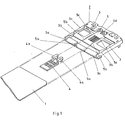
- Figure 1 is a perspective and exploded view of a card reader according to the invention.
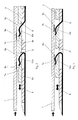
- Figures 2 and 3 are enlarged cross-sections of part of the card reader shown in Figure 1 and showing stages of operation as a card is inserted into the card reader.
- Figure 4 is a plan view of the card reader shown in Figure 1.
- Figure 5 is a sectional view taken on the line y-y of Figure 4, and
- Figure 6 is a sectional view taken on the line X-X of Figure 4.
- As the type of card intended to be used with the card reader of the invention is known to those skilled in the art, it will not be described in detail. Similarly, the circuitry, in conventional card readers, for reading the information from the card is also well-known to those skilled in the art and needs no further description. Moreover, the external detail of the card reader, such as its casing and the slot through which the card is inserted in order to operate the card reader, will not be described in detail since these features are generally known.
- The card reader 2 comprises a
chassis 3 enclosing acarriage 4 arranged for slidable movement in the chassis. A "smart card" 1 can be inserted (through a slot in a casing not shown) into the card reader. Thecard 1 is guided into its correct position by means ofguides carriage 4 is provided with T-shaped stops 4a, 4b which abut the card 2 on insertion. Thecarriage 4 slides along a track partly defined byshoulders portion 5d, which is located at the end oftrack 5, so that it is actuated, by thecard 1, after the card has been received incarriage 4 and has been inserted fully into the card reader. This microswitch operates circuitry (not shown) for supplying power to circuits (not shown) for reading the information stored on the card. Thus, the card is read only when it is in the operating position in which it actuates the switch for enabling the information to be read from the card. - When the card 2 abuts the end stops 4a, 4b the leading edge of the card is at a small distance from the actuating button (not shown) of the microswitch. For example, in the preferred embodiment of the invention this distance is about 1.5mm. At this point, and as shown in Fig. 2, movable contacts, comprising
leaf springs chassis 5, remain clear ofcontact pads card 1. In this position, curled portions of each of theleaf springs inclined faces 8a and 8b ofcamming members sliding carriage 4. - When the
card 1 is inserted further into the card reader in the direction shown by the single headed arrow in Figures 2 and 3, thecarriage 4 is urged towards the raisedportion 5d so that theinclined faces 8a, 8b of the camming means 9a, 9b gradually elevates the curled portions of theleaf springs contacts 10a and 10b, which are conductively attached toleaf springs respective contact pads card 1. At this point, thecontact pads contacts 10a, 10b as shown in Fig. 3. - In the preferred embodiment, six contacts (in two rows of three) engage with six similarly arranged contact pads on the card in the operating position as shown in Fig. 4. However, more or less contacts and contact pads may be provided, as required.
- When the card 2 is removed from the card reader, a
U-shaped leaf spring 11 returnscarriage 4 to its starting position.Bevelled edges 12 on thecarriage 4 also ensure that theleaf springs - Whilst a preferred embodiment of the invention has been described in detail, it will be apparent to a person skilled in the art that various modifications may be made without departing from the scope of the invention defined in the following claims.
Claims (10)
Priority Applications (1)
| Application Number | Priority Date | Filing Date | Title |
|---|---|---|---|
| AT89300507T ATE73560T1 (en) | 1988-01-19 | 1989-01-19 | CARD READER. |
Applications Claiming Priority (2)
| Application Number | Priority Date | Filing Date | Title |
|---|---|---|---|
| GB8801097A GB2214680B (en) | 1988-01-19 | 1988-01-19 | Card reader |
| GB8801097 | 1988-01-19 |
Publications (2)
| Publication Number | Publication Date |
|---|---|
| EP0325458A1 true EP0325458A1 (en) | 1989-07-26 |
| EP0325458B1 EP0325458B1 (en) | 1992-03-11 |
Family
ID=10630172
Family Applications (1)
| Application Number | Title | Priority Date | Filing Date |
|---|---|---|---|
| EP89300507A Expired - Lifetime EP0325458B1 (en) | 1988-01-19 | 1989-01-19 | Card reader |
Country Status (4)
| Country | Link |
|---|---|
| EP (1) | EP0325458B1 (en) |
| AT (1) | ATE73560T1 (en) |
| DE (1) | DE68900942D1 (en) |
| GB (1) | GB2214680B (en) |
Cited By (6)
| Publication number | Priority date | Publication date | Assignee | Title |
|---|---|---|---|---|
| EP0414390A1 (en) * | 1989-08-19 | 1991-02-27 | Nokia Mobile Phones (U.K.) Limited | Card reader |
| EP0444396A1 (en) * | 1990-01-30 | 1991-09-04 | AMPHENOL-TUCHEL ELECTRONICS GmbH | Connection device for a Si-module |
| WO1995013589A1 (en) * | 1993-11-08 | 1995-05-18 | Nicomatic | Electric connector and card reader comprising same |
| WO1996024111A1 (en) * | 1995-02-03 | 1996-08-08 | Framatome Connectors International | Connector for a smart card reader apparatus and card reader comprising same |
| EP0803835A2 (en) * | 1993-12-24 | 1997-10-29 | Itt Composants Et Instruments | Space saving electric connector for an IC memory card |
| DE3937383B4 (en) * | 1988-11-09 | 2011-04-21 | Sagem Communications | Receiving device for chip cards |
Families Citing this family (2)
| Publication number | Priority date | Publication date | Assignee | Title |
|---|---|---|---|---|
| US5404268A (en) * | 1993-07-15 | 1995-04-04 | Dell Usa, L.P. | Interface allowing normal or inverted insertion of data communications card |
| DE102007011821B4 (en) * | 2007-03-12 | 2009-10-29 | Siemens Ag | Contacting device and arrangement for mobile electrical devices |
Citations (5)
| Publication number | Priority date | Publication date | Assignee | Title |
|---|---|---|---|---|
| EP0139593A1 (en) * | 1983-10-27 | 1985-05-02 | Schlumberger Industries | Reading apparatus for electronic memory cards |
| DE3343727A1 (en) * | 1983-12-02 | 1985-06-13 | Siemens AG, 1000 Berlin und 8000 München | Card reader for cash registers |
| DE3343757A1 (en) * | 1983-12-02 | 1985-06-13 | Siemens AG, 1000 Berlin und 8000 München | Card reader for terminals |
| DE3602668A1 (en) * | 1986-01-29 | 1987-07-30 | Allied Corp | CONTACT DEVICE FOR A CHIP CARD |
| EP0234654A1 (en) * | 1986-02-21 | 1987-09-02 | Philips Electronique Grand Public | Apparatus for establishing data transfer by means of a portable electronic card |
-
1988
- 1988-01-19 GB GB8801097A patent/GB2214680B/en not_active Expired - Lifetime
-
1989
- 1989-01-19 DE DE8989300507T patent/DE68900942D1/en not_active Expired - Lifetime
- 1989-01-19 EP EP89300507A patent/EP0325458B1/en not_active Expired - Lifetime
- 1989-01-19 AT AT89300507T patent/ATE73560T1/en not_active IP Right Cessation
Patent Citations (5)
| Publication number | Priority date | Publication date | Assignee | Title |
|---|---|---|---|---|
| EP0139593A1 (en) * | 1983-10-27 | 1985-05-02 | Schlumberger Industries | Reading apparatus for electronic memory cards |
| DE3343727A1 (en) * | 1983-12-02 | 1985-06-13 | Siemens AG, 1000 Berlin und 8000 München | Card reader for cash registers |
| DE3343757A1 (en) * | 1983-12-02 | 1985-06-13 | Siemens AG, 1000 Berlin und 8000 München | Card reader for terminals |
| DE3602668A1 (en) * | 1986-01-29 | 1987-07-30 | Allied Corp | CONTACT DEVICE FOR A CHIP CARD |
| EP0234654A1 (en) * | 1986-02-21 | 1987-09-02 | Philips Electronique Grand Public | Apparatus for establishing data transfer by means of a portable electronic card |
Cited By (9)
| Publication number | Priority date | Publication date | Assignee | Title |
|---|---|---|---|---|
| DE3937383B4 (en) * | 1988-11-09 | 2011-04-21 | Sagem Communications | Receiving device for chip cards |
| EP0414390A1 (en) * | 1989-08-19 | 1991-02-27 | Nokia Mobile Phones (U.K.) Limited | Card reader |
| EP0444396A1 (en) * | 1990-01-30 | 1991-09-04 | AMPHENOL-TUCHEL ELECTRONICS GmbH | Connection device for a Si-module |
| WO1995013589A1 (en) * | 1993-11-08 | 1995-05-18 | Nicomatic | Electric connector and card reader comprising same |
| FR2712430A1 (en) * | 1993-11-08 | 1995-05-19 | Nicomatic | Electrical connector and card reader with it. |
| EP0803835A2 (en) * | 1993-12-24 | 1997-10-29 | Itt Composants Et Instruments | Space saving electric connector for an IC memory card |
| EP0803835A3 (en) * | 1993-12-24 | 2000-11-02 | Itt Composants Et Instruments | Space saving electric connector for an IC memory card |
| WO1996024111A1 (en) * | 1995-02-03 | 1996-08-08 | Framatome Connectors International | Connector for a smart card reader apparatus and card reader comprising same |
| FR2730328A1 (en) * | 1995-02-03 | 1996-08-09 | Connectors Pontarlier | CONNECTOR FOR MICROCIRCUIT CARD READING APPARATUS AND MICROCIRCUIT CARD READING APPARATUS INCLUDING SAME |
Also Published As
| Publication number | Publication date |
|---|---|
| GB8801097D0 (en) | 1988-02-17 |
| ATE73560T1 (en) | 1992-03-15 |
| DE68900942D1 (en) | 1992-04-16 |
| GB2214680B (en) | 1991-07-31 |
| EP0325458B1 (en) | 1992-03-11 |
| GB2214680A (en) | 1989-09-06 |
Similar Documents
| Publication | Publication Date | Title |
|---|---|---|
| US6761575B2 (en) | Ergonomic electrical connector for a smart card | |
| EP1602058B1 (en) | Connector for a smart card, comprising an integrated drawer/slider for the card | |
| US6149466A (en) | Compact smart card electrical connector | |
| US5331138A (en) | Hybrid card reader | |
| US6976879B2 (en) | Card connector | |
| US5315478A (en) | Memory card tray for portable computer | |
| US5673180A (en) | Case for microcircuit card reader | |
| EP0704813B1 (en) | Ic card information processing apparatus | |
| US6561431B2 (en) | Card reader and the mobile electronic device equipped with it | |
| US6655590B1 (en) | Smart card reader | |
| EP1321886B1 (en) | Card connector | |
| JPH0916739A (en) | Contact device for chip card | |
| JP2000357210A (en) | Contact device | |
| EP0325458B1 (en) | Card reader | |
| US6364674B1 (en) | Ejecting apparatus | |
| EP0351103B1 (en) | Card reader | |
| EP0494503A1 (en) | Card reader | |
| US5670769A (en) | Case for microcircuit card reader | |
| US5971280A (en) | Card reading device including a contact and a card carrier parts | |
| US6802448B2 (en) | Compact smart card reader with ejector | |
| KR20090056788A (en) | Memory card connector | |
| JPH02116989A (en) | Scanner for chip card | |
| US6652300B2 (en) | Card connector device having slide member for discharging card | |
| CN1221159A (en) | Chip card reader and telephone comprising such reader | |
| EP0328692A1 (en) | Sealing holder of ic card |
Legal Events
| Date | Code | Title | Description |
|---|---|---|---|
| PUAI | Public reference made under article 153(3) epc to a published international application that has entered the european phase |
Free format text: ORIGINAL CODE: 0009012 |
|
| AK | Designated contracting states |
Kind code of ref document: A1 Designated state(s): AT BE CH DE ES FR GB GR IT LI LU NL SE |
|
| 17P | Request for examination filed |
Effective date: 19890809 |
|
| 17Q | First examination report despatched |
Effective date: 19910222 |
|
| GRAA | (expected) grant |
Free format text: ORIGINAL CODE: 0009210 |
|
| STAA | Information on the status of an ep patent application or granted ep patent |
Free format text: STATUS: THE PATENT HAS BEEN GRANTED |
|
| AK | Designated contracting states |
Kind code of ref document: B1 Designated state(s): AT BE CH DE ES FR GB GR IT LI LU NL SE |
|
| PG25 | Lapsed in a contracting state [announced via postgrant information from national office to epo] |
Ref country code: CH Effective date: 19920311 Ref country code: AT Effective date: 19920311 Ref country code: LI Effective date: 19920311 Ref country code: GR Free format text: LAPSE BECAUSE OF FAILURE TO SUBMIT A TRANSLATION OF THE DESCRIPTION OR TO PAY THE FEE WITHIN THE PRESCRIBED TIME-LIMIT Effective date: 19920311 Ref country code: BE Effective date: 19920311 Ref country code: ES Free format text: THE PATENT HAS BEEN ANNULLED BY A DECISION OF A NATIONAL AUTHORITY Effective date: 19920311 |
|
| REF | Corresponds to: |
Ref document number: 73560 Country of ref document: AT Date of ref document: 19920315 Kind code of ref document: T |
|
| REF | Corresponds to: |
Ref document number: 68900942 Country of ref document: DE Date of ref document: 19920416 |
|
| ET | Fr: translation filed | ||
| ITF | It: translation for a ep patent filed |
Owner name: MODIANO & ASSOCIATI S.R.L. |
|
| REG | Reference to a national code |
Ref country code: CH Ref legal event code: PL |
|
| PLBE | No opposition filed within time limit |
Free format text: ORIGINAL CODE: 0009261 |
|
| PG25 | Lapsed in a contracting state [announced via postgrant information from national office to epo] |
Ref country code: LU Free format text: LAPSE BECAUSE OF NON-PAYMENT OF DUE FEES Effective date: 19930131 |
|
| 26N | No opposition filed | ||
| ITPR | It: changes in ownership of a european patent |
Owner name: CAMBIO RAGIONE SOCIALE;NOKIA MOBILE PHONES ( UK ) |
|
| REG | Reference to a national code |
Ref country code: FR Ref legal event code: CD |
|
| NLT1 | Nl: modifications of names registered in virtue of documents presented to the patent office pursuant to art. 16 a, paragraph 1 |
Owner name: NOKIA MOBILE PHONES (U.K.) LIMITED TE CAMBERLEY, G |
|
| EAL | Se: european patent in force in sweden |
Ref document number: 89300507.4 |
|
| REG | Reference to a national code |
Ref country code: GB Ref legal event code: IF02 |
|
| PGFP | Annual fee paid to national office [announced via postgrant information from national office to epo] |
Ref country code: SE Payment date: 20030107 Year of fee payment: 15 |
|
| PG25 | Lapsed in a contracting state [announced via postgrant information from national office to epo] |
Ref country code: SE Free format text: LAPSE BECAUSE OF NON-PAYMENT OF DUE FEES Effective date: 20040120 |
|
| EUG | Se: european patent has lapsed | ||
| PGFP | Annual fee paid to national office [announced via postgrant information from national office to epo] |
Ref country code: NL Payment date: 20050103 Year of fee payment: 17 |
|
| PGFP | Annual fee paid to national office [announced via postgrant information from national office to epo] |
Ref country code: FR Payment date: 20050110 Year of fee payment: 17 |
|
| PG25 | Lapsed in a contracting state [announced via postgrant information from national office to epo] |
Ref country code: IT Free format text: LAPSE BECAUSE OF NON-PAYMENT OF DUE FEES Effective date: 20050119 |
|
| PG25 | Lapsed in a contracting state [announced via postgrant information from national office to epo] |
Ref country code: FR Free format text: LAPSE BECAUSE OF NON-PAYMENT OF DUE FEES Effective date: 20060131 |
|
| PG25 | Lapsed in a contracting state [announced via postgrant information from national office to epo] |
Ref country code: NL Free format text: LAPSE BECAUSE OF NON-PAYMENT OF DUE FEES Effective date: 20060801 |
|
| NLV4 | Nl: lapsed or anulled due to non-payment of the annual fee |
Effective date: 20060801 |
|
| REG | Reference to a national code |
Ref country code: FR Ref legal event code: ST Effective date: 20060929 |
|
| PGFP | Annual fee paid to national office [announced via postgrant information from national office to epo] |
Ref country code: GB Payment date: 20080116 Year of fee payment: 20 Ref country code: DE Payment date: 20080117 Year of fee payment: 20 |
|
| REG | Reference to a national code |
Ref country code: GB Ref legal event code: PE20 Expiry date: 20090118 |
|
| PG25 | Lapsed in a contracting state [announced via postgrant information from national office to epo] |
Ref country code: GB Free format text: LAPSE BECAUSE OF EXPIRATION OF PROTECTION Effective date: 20090118 |