EP0325169A1 - Method and forming device for continuously extruded sections - Google Patents
Method and forming device for continuously extruded sections Download PDFInfo
- Publication number
- EP0325169A1 EP0325169A1 EP19890100534 EP89100534A EP0325169A1 EP 0325169 A1 EP0325169 A1 EP 0325169A1 EP 19890100534 EP19890100534 EP 19890100534 EP 89100534 A EP89100534 A EP 89100534A EP 0325169 A1 EP0325169 A1 EP 0325169A1
- Authority
- EP
- European Patent Office
- Prior art keywords
- cross
- channel
- profile
- molding device
- basic cross
- Prior art date
- Legal status (The legal status is an assumption and is not a legal conclusion. Google has not performed a legal analysis and makes no representation as to the accuracy of the status listed.)
- Withdrawn
Links
Images


Classifications
-
- B—PERFORMING OPERATIONS; TRANSPORTING
- B29—WORKING OF PLASTICS; WORKING OF SUBSTANCES IN A PLASTIC STATE IN GENERAL
- B29C—SHAPING OR JOINING OF PLASTICS; SHAPING OF MATERIAL IN A PLASTIC STATE, NOT OTHERWISE PROVIDED FOR; AFTER-TREATMENT OF THE SHAPED PRODUCTS, e.g. REPAIRING
- B29C43/00—Compression moulding, i.e. applying external pressure to flow the moulding material; Apparatus therefor
- B29C43/22—Compression moulding, i.e. applying external pressure to flow the moulding material; Apparatus therefor of articles of indefinite length
- B29C43/222—Compression moulding, i.e. applying external pressure to flow the moulding material; Apparatus therefor of articles of indefinite length characterised by the shape of the surface
-
- B—PERFORMING OPERATIONS; TRANSPORTING
- B29—WORKING OF PLASTICS; WORKING OF SUBSTANCES IN A PLASTIC STATE IN GENERAL
- B29C—SHAPING OR JOINING OF PLASTICS; SHAPING OF MATERIAL IN A PLASTIC STATE, NOT OTHERWISE PROVIDED FOR; AFTER-TREATMENT OF THE SHAPED PRODUCTS, e.g. REPAIRING
- B29C70/00—Shaping composites, i.e. plastics material comprising reinforcements, fillers or preformed parts, e.g. inserts
- B29C70/04—Shaping composites, i.e. plastics material comprising reinforcements, fillers or preformed parts, e.g. inserts comprising reinforcements only, e.g. self-reinforcing plastics
- B29C70/28—Shaping operations therefor
- B29C70/40—Shaping or impregnating by compression not applied
- B29C70/50—Shaping or impregnating by compression not applied for producing articles of indefinite length, e.g. prepregs, sheet moulding compounds [SMC] or cross moulding compounds [XMC]
- B29C70/52—Pultrusion, i.e. forming and compressing by continuously pulling through a die
Definitions
- the invention relates to a method for producing extruded profile bodies according to the preamble of claim 1 and to a molding device for producing extruded profile bodies according to the preamble of claim 2.
- Profile bodies made of fiber-reinforced synthetic resin produced by extrusion can generally only be produced with a longitudinally continuous profile, which is determined by the contour of the nozzle cross section of the nozzle channel of the molding device.
- this molding aid which is designed as a shaped wire, such helical shapes can be formed in addition to longitudinal grooves within the contour of the anchoring rod.
- the invention has for its object to provide a method and an apparatus for producing extruded profile bodies made of curable synthetic resin, with which any additional profiles in the form of raised projections, as well as in the form of recessed depressions can be easily attached to the outside of the profile body.
- the invention provides for the first time the possibility of providing any extruded profile body with any external profile, as may be desired for a large number of applications.
- strip-shaped profile bodies can be provided on one or both sides with markings such as numbers, letters, etc. or with ornaments that improve the visual appearance.
- functionally essential transverse deformations can be applied in the extruded profile body, for example ribbing or the like.
- the additional profiling can be carried out extremely precisely without the need for an additional operation. Any undesirable force reactions on the profile body during its manufacture are also avoided, since no pressure effects are exerted on the profile body by the formation according to the invention that go beyond the pressure effect of a fixed boundary wall.
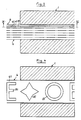
- the molding device illustrated in the drawing for the production of extruded profile bodies made of curable synthetic resin, in which reinforcing fibers are embedded extending over the length of the profile body 4, comprises in particular a horizontally divided nozzle housing 1, the housing parts of which jointly delimit a nozzle channel 2 which extends over the Length of the nozzle housing 1 extends.
- the nozzle channel 2 as can be seen in particular in FIG. 2, has a basic cross-sectional contour which is defined in FIG. 2 by the solid lines and the dashed line 3. This basic cross-sectional contour of the nozzle channel 2 corresponds to the reason Cross section of a profile body 4 to be produced, as it emerges as an extruded profile from the outlet end of the nozzle housing 1.
- the nozzle channel 2 has a channel extension 5, which in turn is longitudinally adjacent to the basic cross-sectional contour above the contour line part 3 and in the example shown has the shape of a broad, flat, rectilinearly delimited rectangle.
- any other desirable or suitable cross-sectional shape for the channel extension 5 is also possible.
- the nozzle housing 1 is assigned an endlessly revolving forming band 6, which corresponds in its basic cross section to the cross section of the channel extension 5 and is guided longitudinally in the channel extension 5 with its working strand 7 as it passes through the nozzle channel 2.
- the forming strip 6 essentially completely fills the channel extension 5 with its basic cross-sectional part and offers an outer surface facing the nozzle channel 2 in the area of the working strand 7 with an essentially straight cross-contour line in the area of the basic cross-section. This cross-contour line corresponds to the contour line part 3 and falls during operation with this together.
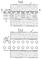
- the shaping tape 6 has on the outside transverse profile areas which either form projections projecting outward over the outer surface of the shaping tape 6 or depressions recessed into the outer surface, wherein the shaping tape 6 can be provided with cross-profile areas of both types.
- the forming belt 6 can be formed by two sub-belts 61, 62 which are aligned one above the other, the transverse profile regions being formed by recesses 81 in the outer belt part 62. As can be seen in FIG. 4, these cutouts 81 can have a wide variety of shapes and form letters, ornaments, numbers or other markings.
- the forming belt 6 can also, as shown in FIGS. 5 to 10 can be seen as a one-piece band body with outside transverse profile areas.
- the transverse profile regions can be formed by recesses, for example punched-outs, which extend over the entire thickness of the band body 6, but can also be formed as recesses 82 which extend only over part of the thickness of the band body 6, as is shown, for example, in FIG. 8 illustrates.
- FIG. 7, on the other hand illustrates an embodiment of the forming belt 6, in which the transverse profile regions are formed by raised projections 83 integrally molded on the outside of the forming belt 6.
- the transverse profile regions can also be formed by indentations 84 or indentations 85, which can also be provided next to one another in the band body 6.
- the shaping band 6 can also have a thin carrier band part 63 and profile parts 86 fastened on the outside as transverse profile regions.
- the forming belt is preferably endless and runs around deflection rollers 9, 10, but can also be designed as an element that is used only once.
- the shaping tape 6 is preferably designed to be flexible, it being able to consist of sheet metal, fiber-reinforced synthetic resin, rubber or other suitable materials.
- the forming belt 6 is also possible to design the forming belt 6 as a chain link belt, the chain links of which are connected to one another in an articulated manner and form plate bodies which jointlessly adjoin one another in the area of the working strand 7 and together form a closed boundary surface facing the nozzle channel 2 with raised, protruding or recessed transverse profile areas.
- Such an embodiment can also be endless.
- a continuous strand 11 of reinforcing fibers is essentially continuously passed through the nozzle housing 1 and its nozzle channel 2 in FIG. 1 pulled through from right to left, and in the nozzle channel 2 the fiber strand 11 soaked there completely with synthetic resin is shaped and cured into a profile body 4 corresponding in its basic cross-section to the basic cross-sectional contour of the nozzle channel 2. Due to the leading to the fiber strand 11 before its entry into the nozzle channel 1, which passes together with the fiber strand 11 through the nozzle channel 2, the profile profile 4 that is created continuously is provided on the outside with any cross profiles, as they are from optical and / or functional reasons are desired. After leaving the nozzle channel 2, the forming strip 6 lifts off from the profile body 4 and leaves the raised and / or recessed additional profiling behind.
Abstract
Description
Die Erfindung bezieht sich auf ein Verfahren zur Herstellung von stranggezogenen Profilkörpern gemäß dem Oberbegriff des Anspruchs 1 sowie auf eine Formvorrichtung zur Herstellung von stranggezogenen Profilkörpern gemäß dem Oberbegriff des Anspruchs 2.The invention relates to a method for producing extruded profile bodies according to the preamble of
Durch Strangziehen hergestellte Profilkörper aus faserverstärktem Kunstharz sind im allgemeinen lediglich mit einer längsdurchgehenden Profilierung herstellbar, die durch die Kontur des Düsenquerschnitts des Düsenkanals der Formvorrichtung bestimmt ist. Darüber hinaus ist es bekannt (DE-PS 31 45 153), Verankerungsstäbe mit einer in die Kontur eingelassenen, nicht ausschließlich längslaufenden Nutung herzustellen. Dies geschieht mit Hilfe eines an den Faserstrang vor dessen Einlauf in den Düsenkanal der Formvorrichtung herangeführten, fortlaufenden Formhilfsmittels, das gemeinsam mit dem Faserstrang durch den Düsenkanal hindurchgeführt und anschließend unter Zurücklassen einer Nutvertiefung entfernt werden kann. Mit Hilfe dieses als Formdraht ausgebildeten Formhilfsmittels können neben längslaufenden Nuten innerhalb der Kontur des Verankerungsstabes auch solche wendelförmiger Gestalt gebildet werden.Profile bodies made of fiber-reinforced synthetic resin produced by extrusion can generally only be produced with a longitudinally continuous profile, which is determined by the contour of the nozzle cross section of the nozzle channel of the molding device. In addition, it is known (DE-PS 31 45 153) to produce anchoring rods with a groove that is embedded in the contour and is not exclusively longitudinal. This is done with the aid of a continuous molding aid which is brought up to the fiber strand before it enters the nozzle channel of the shaping device and can be passed through the nozzle channel together with the fiber strand and then removed with a groove recess left behind. With the aid of this molding aid, which is designed as a shaped wire, such helical shapes can be formed in addition to longitudinal grooves within the contour of the anchoring rod.
Der Erfindung liegt die Aufgabe zugrunde, ein Verfahren und eine Vorrichtung zur Herstellung von stranggezogenen Profilkörpern aus aushärtbarem Kunstharz zu schaffen, mit denen auf der Außenseite des Profilkörpers beliebige Zusatzprofilierungen sowohl in Gestalt erhabener Vorsprünge, als auch in Form eingesenkter Vertiefungen einfach angebracht werden können.The invention has for its object to provide a method and an apparatus for producing extruded profile bodies made of curable synthetic resin, with which any additional profiles in the form of raised projections, as well as in the form of recessed depressions can be easily attached to the outside of the profile body.
Die Erfindung löst diese Aufgabe durch ein Verfahren gemäß Anspruch 1 sowie eine Formvorrichtung gemäß Anspruchs 2. Hinsichtlich wesentlicher weiterer Ausgestaltungen wird auf die Ansprüche 3 bis 14 verwiesen.The invention solves this problem by means of a method according to
Die Erfindung schafft auf besonders einfache und kostengünstige Weise erstmals die Möglichkeit, beliebige Strangprofilkörper mit einer beliebigen Außenprofilierung zu versehen, wie sie für eine Vielzahl von Anwendungszwecken erwünscht sein kann. So können beispielsweise leistenförmige Profilkörper ein- oder beidseitig mit Markierungen wie Ziffern, Buchstaben etc. oder auch mit Ornamenten versehen werden, die das optische Erscheinungsbild verbessern. Statt dessen oder zusätzlich können in dem Strangprofilkörper auch funktionswesentliche Querverformungen angebracht werden, beispielsweise eine Verrippung oder ähnliches. Die Zusatzprofilierung ist dabei außerordentlich präzise ausführbar, ohne daß ein zusätzlicher Arbeitsgang erforderlich ist. Auch sind irgendwelche unerwünschten Kraftrückwirkungen auf dem Profilkörper bei dessen Herstellung vermieden, da von dem Formband erfindungsgemäßer Ausbildung keine Druckwirkungen auf den Profilkörper ausgeübt werden, die über die Druckwirkung einer feststehenden Begrenzungswand hinausgehen.In a particularly simple and cost-effective manner, the invention provides for the first time the possibility of providing any extruded profile body with any external profile, as may be desired for a large number of applications. For example, strip-shaped profile bodies can be provided on one or both sides with markings such as numbers, letters, etc. or with ornaments that improve the visual appearance. Instead of or in addition, functionally essential transverse deformations can be applied in the extruded profile body, for example ribbing or the like. The additional profiling can be carried out extremely precisely without the need for an additional operation. Any undesirable force reactions on the profile body during its manufacture are also avoided, since no pressure effects are exerted on the profile body by the formation according to the invention that go beyond the pressure effect of a fixed boundary wall.
Weitere Einzelheiten und Vorteile ergeben sich aus der nachfolgenden Beschreibung und der Zeichnung, die mehrere Ausführungsbeispiele einer Formvorrichtung erfindungsgemäßer Ausbildung schematisch veranschaulicht. In der Zeichnung zeigen:
- Fig. 1 eine schematische, abgebrochene Seitenansicht einer Formvorrichtung nach der Erfindung,
- Fig. 2 eine Ansicht der Stirnseite des den Düsenkanal begrenzenden Düsengehäuses,
- Fig. 3 einen abgebrochenen vertikalen Teillängsschnitt durch das Auslaufende des Düsengehäuses,
- Fig. 4 einen abgebrochenen Schnitt nach der Linie IV-IV in Fig. 3,
- Fig. 5 eine Darstellung ähnlich Fig. 3 zur Veranschaulichung einer zweiten Formbandausführung,
- Fig. 6 eine Schnittdarstellung ähnlich Fig. 4 nach der Linie VI-VI in Fig. 5,
- Fig. 7 eine Darstellung ähnlich Fig. 5 zur Veranschaulichung einer dritten Formbandausführung,
- Fig. 8 eine Darstellung ähnlich Fig. 7 zur Veranschaulichung einer vierten Formbandausführung,
- Fig. 9 eine Darstellung ähnlich Fig. 8 zur Veranschaulichung einer fünften Formbandausführung,
- Fig. 10 eine Darstellung ähnlich Fig. 9 zur Veranschaulichung einer sechsten Formbandausführung.
- Fig. 1 is a schematic, broken side view a molding device according to the invention,
- 2 shows a view of the end face of the nozzle housing delimiting the nozzle channel,
- 3 shows a broken vertical partial longitudinal section through the outlet end of the nozzle housing,
- 4 shows a broken section along the line IV-IV in FIG. 3,
- 5 shows a representation similar to FIG. 3 to illustrate a second form of ribbon,
- 6 is a sectional view similar to FIG. 4 along the line VI-VI in FIG. 5,
- FIG. 7 shows a representation similar to FIG. 5 to illustrate a third form of ribbon,
- 8 shows a representation similar to FIG. 7 to illustrate a fourth form of ribbon,
- FIG. 9 shows a representation similar to FIG. 8 to illustrate a fifth form of ribbon,
- FIG. 10 shows a representation similar to FIG. 9 to illustrate a sixth form of ribbon.
Die in der Zeichnung veranschaulichte Formvorrichtung zur Herstellung von stranggezogenen Profilkörpern aus aushärtbarem Kunstharz, in das sich über die Länge der Profilkörper 4 erstreckende Verstärkungsfasern eingebettet sind, umfaßt im einzelnen ein horizontal geteiltes Düsengehäuse 1, dessen Gehäuseteile gemeinsam einen Düsenkanal 2 umgrenzen, der sich über die Länge des Düsengehäuses 1 erstreckt. Der Düsenkanal 2 hat dabei, wie dies insbesondere der Fig. 2 entnommen werden kann, eine Grundquerschnittskontur, die in Fig. 2 durch die ausgezogenenen Linien sowie die gestrichelte Linie 3 definiert wird. Diese Grundquerschnittskontur des Düsenkanals 2 entspricht dabei dem Grund querschnitt eines herzustellenden Profilkörpers 4, wie er als Strangprofil aus dem Auslaßende des Düsengehäuses 1 austritt.The molding device illustrated in the drawing for the production of extruded profile bodies made of curable synthetic resin, in which reinforcing fibers are embedded extending over the length of the
Der Düsenkanal 2 weist bei dem dargestellten Beispiel eine an die Grundquerschnittskontur oberhalb der Konturlinienteils 3 unmittelbar angrenzende, ihrerseits längsgerichtete Kanalerweiterung 5 auf, die bei dem dargestellten Beispiel die Form eines breiten, flachen, geradlinig begrenzten Rechtecks aufweist. Grundsätzlich ist aber auch jede andere wünschenswerte oder geeignete Querschnittsgestalt für die Kanalerweiterung 5 möglich.In the example shown, the
Dem Düsengehäuse 1 ist bei dem dargestellten Beispiel ein endlos umlaufendes Formband 6 zugeordnet, das in seinem Grundquerschnitt dem Querschnitt der Kanalerweiterung 5 entspricht und mit seinem Arbeitstrum 7 beim Durchlaufen des Düsenkanals 2 in der Kanalerweiterung 5 längsgeführt ist. Das Formband 6 füllt dabei mit seinem Grundquerschnittsteil die Kanalerweiterung 5 im wesentlichen vollständig aus und bietet eine dem Düsenkanal 2 im Bereich des Arbeitstrums 7 zugewandte Außenfläche mit einer im Bereich des Grundquerschnitts im wesentlichen geraden Querkonturlinie dar. Diese Querkonturlinie entspricht dem Konturlinienteil 3 und fällt im Betrieb mit diesem zusammen.In the example shown, the
Das Formband 6 weist dabei außenseitig Querprofilbereiche auf, die entweder über die Außenfläche des Formbandes 6 nach außen vorstehende Vorsprünge oder in die Außenfläche eingesenkte Vertiefungen bilden, wobei das Formband 6 mit Querprofilbereichen beider Arten versehen sein kann.The
Wie der Fig. 3 und 4 entnommen werden kann, kann das Formband 6 von zwei fluchtend übereinanderliegenden Teilbändern 61,62 gebildet sein, wobei die Querprofilbereiche von Aussparungen 81 im äußeren Bandteil 62 gebildet sind. Diese Aussparungen 81 können, wie das die Fig. 4 erkennen läßt, die unterschiedlichsten Formgestaltungen haben und Buchstaben, Ornamente, Ziffern oder sonstige Markierungen bilden. Das Formband 6 kann aber auch, wie dies die Fig. 5 bis 10 erkennen lassen, als einteiliger Bandkörper mit außenseitigen Querprofilbereichen ausgebildet sein. Die Querprofilbereiche können dabei von sich über die gesamte Dicke des Bandkörpers 6 erstreckenden Aussparungen, z.B. Ausstanzungen, gebildet sein, können jedoch auch als Aussparungen 82 ausgebildet sein, die sich lediglich über einen Teil der Dicke des Bandkörpers 6 erstrecken, wie dies z.B. die Fig. 8 veranschaulicht. Die Fig. 7 veranschaulicht demgegenüber eine Ausführung des Formbandes 6, bei der die Querprofilbereiche von an der Außenseite des Formbandes 6 integral angeformten, erhabenen Vorsprüngen 83 gebildet sind. Statt dessen können, wie dies aus den Fig. 9 und 10 hervorgeht, die Querprofilbereiche auch von Einprägungen 84 bzw. Ausprägungen 85 gebildet sein, die auch nebeneinander im Bandkörper 6 vorgesehen sein können.As can be seen from FIGS. 3 and 4, the forming
Das Formband 6 kann gemäß Fig. 5 auch einen dünnen Trägerbandteil 63 und als Querprofilbereiche außenseitig auf diesem befestigte Profilteile 86 aufweisen.According to FIG. 5, the
Das Formband ist bevorzugt endlos ausgebildet und läuft um Umlenkrollen 9,10 um, kann jedoch auch als lediglich einmalig zur Verwendung kommendes Element ausgebildet sein. Das Formband 6 ist bevorzugt biegsam ausgebildet, wobei es aus Metallblech, aus faserverstärktem Kunstharz, aus Gummi oder sonst geeigneten Werkstoffen bestehen kann.The forming belt is preferably endless and runs around
Statt dessen ist es aber auch möglich, das Formband 6 als Kettengliederband auszubilden, dessen gelenkig untereinander verbundenen Kettenglieder Plattenkörper bilden, die im Bereich des Arbeitstrums 7 fugenlos aneinandergrenzen und gemeinsam eine dem Düsenkanal 2 zugewandte geschlossene Begrenzungsfläche mit erhaben vorstehenden oder vertieft eingesenkten Querprofilbereichen bilden. Auch eine solche Ausgestaltung kann endlos ausgeführt sein.Instead of this, however, it is also possible to design the forming
Zur Bildung der Profilkörper 4 wird ein fortlaufender Strang 11 aus Verstärkungsfasern im wesentlichen kontinuierlich durch das Düsengehäuse 1 und dessen Düsenkanal 2 in Fig. 1 von rechts nach links hindurchgezogen, und im Düsenkanal 2 wird der dort mit Kunstharz völlig durchtränkte Faserstrang 11 zu einem in seinem Grundquerschnitt der Grundquerschnittskontur des Düsenkanals 2 entsprechenden Profilkörper 4 geformt sowie ausgehärtet. Durch das an den Faserstrang 11 vor dessen Einlauf in den Düsenkanal 1 herangeführte Formband 6, das gemeinsam mit dem Faserstrang 11 den Düsenkanal 2 durchläuft, wird durch die Wirkung der Querprofilbereiche der fortlaufend entstehende Profilkörper 4 außenseitig mit beliebigen Querprofilierungen versehen, wie sie aus optischen und/oder funktionellen Gründen erwünscht sind. Nach Verlassen des Düsenkanals 2 hebt sich das Formband 6 vom Profilkörper 4 ab und läßt die erhabene und/oder eingesenkte Zusatzprofilierung zurück.To form the
Claims (14)
Applications Claiming Priority (2)
| Application Number | Priority Date | Filing Date | Title |
|---|---|---|---|
| DE19883801139 DE3801139C1 (en) | 1988-01-16 | 1988-01-16 | |
| DE3801139 | 1988-01-16 |
Publications (1)
| Publication Number | Publication Date |
|---|---|
| EP0325169A1 true EP0325169A1 (en) | 1989-07-26 |
Family
ID=6345410
Family Applications (1)
| Application Number | Title | Priority Date | Filing Date |
|---|---|---|---|
| EP19890100534 Withdrawn EP0325169A1 (en) | 1988-01-16 | 1989-01-13 | Method and forming device for continuously extruded sections |
Country Status (2)
| Country | Link |
|---|---|
| EP (1) | EP0325169A1 (en) |
| DE (1) | DE3801139C1 (en) |
Families Citing this family (5)
| Publication number | Priority date | Publication date | Assignee | Title |
|---|---|---|---|---|
| US9016221B2 (en) | 2004-02-17 | 2015-04-28 | University Of Florida Research Foundation, Inc. | Surface topographies for non-toxic bioadhesion control |
| US7650848B2 (en) | 2004-02-17 | 2010-01-26 | University Of Florida Research Foundation, Inc. | Surface topographies for non-toxic bioadhesion control |
| US10150245B2 (en) | 2008-11-11 | 2018-12-11 | University Of Florida Research Foundation, Inc. | Method of patterning a surface and articles comprising the same |
| DE102010046609A1 (en) | 2010-09-25 | 2011-05-05 | Daimler Ag | Plastic-fiber composite component has basic fiber structure which consists of flux equitable deposited continuous filaments with respect to predetermined geometry of component |
| US9937655B2 (en) | 2011-06-15 | 2018-04-10 | University Of Florida Research Foundation, Inc. | Method of manufacturing catheter for antimicrobial control |
Citations (4)
| Publication number | Priority date | Publication date | Assignee | Title |
|---|---|---|---|---|
| US3455765A (en) * | 1964-09-29 | 1969-07-15 | Mancar Trust | Apparatus for producing fiber-reinforced plastics sections,particularly longitudinally tapering sections,with the aid of a mandrel |
| US3795471A (en) * | 1971-03-05 | 1974-03-05 | Amunt Spa | Apparatus for shaping hollow extrudates of a plastic material |
| US4025257A (en) * | 1972-05-17 | 1977-05-24 | Sekisui Kagaku Kogyo Kabushiki Kaisha | Apparatus for continuously manufacturing an elongated reinforced shaped article |
| DE3247145A1 (en) * | 1982-12-21 | 1984-07-05 | Held, Kurt, 7218 Trossingen | METAL CONTINUOUS PRESS RIBBON WITH STRUCTURED SURFACE FOR DOUBLE BAND PRESSES |
Family Cites Families (1)
| Publication number | Priority date | Publication date | Assignee | Title |
|---|---|---|---|---|
| DE3145153C2 (en) * | 1981-11-13 | 1984-10-04 | Röchling Haren KG, 4472 Haren | Process for the production of a drawn anchoring rod from hardenable synthetic resin |
-
1988
- 1988-01-16 DE DE19883801139 patent/DE3801139C1/de not_active Expired
-
1989
- 1989-01-13 EP EP19890100534 patent/EP0325169A1/en not_active Withdrawn
Patent Citations (4)
| Publication number | Priority date | Publication date | Assignee | Title |
|---|---|---|---|---|
| US3455765A (en) * | 1964-09-29 | 1969-07-15 | Mancar Trust | Apparatus for producing fiber-reinforced plastics sections,particularly longitudinally tapering sections,with the aid of a mandrel |
| US3795471A (en) * | 1971-03-05 | 1974-03-05 | Amunt Spa | Apparatus for shaping hollow extrudates of a plastic material |
| US4025257A (en) * | 1972-05-17 | 1977-05-24 | Sekisui Kagaku Kogyo Kabushiki Kaisha | Apparatus for continuously manufacturing an elongated reinforced shaped article |
| DE3247145A1 (en) * | 1982-12-21 | 1984-07-05 | Held, Kurt, 7218 Trossingen | METAL CONTINUOUS PRESS RIBBON WITH STRUCTURED SURFACE FOR DOUBLE BAND PRESSES |
Also Published As
| Publication number | Publication date |
|---|---|
| DE3801139C1 (en) | 1989-03-09 |
Similar Documents
| Publication | Publication Date | Title |
|---|---|---|
| DE2937454C2 (en) | Composite profile, in particular for windows, doors and facades, and a method for producing the composite profile | |
| DE3020447A1 (en) | METHOD FOR PRODUCING A U-PROFILE TRIM | |
| DE2524308A1 (en) | METHOD AND DEVICE FOR MANUFACTURING A HANDRAIL OR A HAND RAIL | |
| EP0158118A2 (en) | Method and apparatus for producing composite sections | |
| EP0225846B1 (en) | Method and injection tool for making a plastic link conveyer, in particular a ball chain | |
| EP0161589B1 (en) | Process and device for making a plastic injection-moulded article, especially a profiled listel for a vehicle | |
| DE3926509C2 (en) | ||
| EP0026795B1 (en) | Profiled building strip, especially a profile strip for the manufacture of window frames, and process for its manufacture | |
| EP0021054B1 (en) | Process and device for the continuous production of reinforced profiled belts | |
| DE3223093A1 (en) | METHOD AND ARRANGEMENT FOR PRODUCING FIBER REINFORCED OBJECTS | |
| DE3438448C2 (en) | ||
| EP0325169A1 (en) | Method and forming device for continuously extruded sections | |
| DE2518037A1 (en) | WAVE GUIDE AND PROCESS FOR ITS MANUFACTURING | |
| DE3208916A1 (en) | System for continuous production of profile bars, for example handrail profiles, from plastic | |
| DE3831274C2 (en) | ||
| DE102012110396A1 (en) | Method and device for producing a maturing belt | |
| DE2209278A1 (en) | Drive belt | |
| EP0578797B1 (en) | Process and device for making the corners of sealing frames | |
| DE60116740T2 (en) | EXTRUSION TOOL | |
| EP0441287A1 (en) | Metallic insert band for trimming and sealing strips | |
| DE1610368B1 (en) | Method and device for producing the fastener link chains of plastic zippers | |
| DE4213466C2 (en) | Process for the production of profile strips | |
| DE2802127C2 (en) | ||
| DE102015007779A1 (en) | Method for producing a plastic drive cable | |
| DE2950580C2 (en) | Measuring tape made from a tape-like plastic layer |
Legal Events
| Date | Code | Title | Description |
|---|---|---|---|
| PUAI | Public reference made under article 153(3) epc to a published international application that has entered the european phase |
Free format text: ORIGINAL CODE: 0009012 |
|
| AK | Designated contracting states |
Kind code of ref document: A1 Designated state(s): AT BE CH FR GB LI SE |
|
| RIN1 | Information on inventor provided before grant (corrected) |
Inventor name: LUEGERING , ANTON, DIPL.-ING. |
|
| 17P | Request for examination filed |
Effective date: 19900118 |
|
| 17Q | First examination report despatched |
Effective date: 19910430 |
|
| STAA | Information on the status of an ep patent application or granted ep patent |
Free format text: STATUS: THE APPLICATION IS DEEMED TO BE WITHDRAWN |
|
| 18D | Application deemed to be withdrawn |
Effective date: 19921027 |