EP0325071B1 - Protection device for electrical installations - Google Patents
Protection device for electrical installations Download PDFInfo
- Publication number
- EP0325071B1 EP0325071B1 EP88403298A EP88403298A EP0325071B1 EP 0325071 B1 EP0325071 B1 EP 0325071B1 EP 88403298 A EP88403298 A EP 88403298A EP 88403298 A EP88403298 A EP 88403298A EP 0325071 B1 EP0325071 B1 EP 0325071B1
- Authority
- EP
- European Patent Office
- Prior art keywords
- zone
- zones
- triggering
- contact
- relay
- Prior art date
- Legal status (The legal status is an assumption and is not a legal conclusion. Google has not performed a legal analysis and makes no representation as to the accuracy of the status listed.)
- Expired - Lifetime
Links
Images


Classifications
-
- H—ELECTRICITY
- H01—ELECTRIC ELEMENTS
- H01H—ELECTRIC SWITCHES; RELAYS; SELECTORS; EMERGENCY PROTECTIVE DEVICES
- H01H71/00—Details of the protective switches or relays covered by groups H01H73/00 - H01H83/00
- H01H71/02—Housings; Casings; Bases; Mountings
-
- H—ELECTRICITY
- H01—ELECTRIC ELEMENTS
- H01H—ELECTRIC SWITCHES; RELAYS; SELECTORS; EMERGENCY PROTECTIVE DEVICES
- H01H71/00—Details of the protective switches or relays covered by groups H01H73/00 - H01H83/00
- H01H71/02—Housings; Casings; Bases; Mountings
- H01H71/0207—Mounting or assembling the different parts of the circuit breaker
- H01H71/0221—Majority of parts mounted on central frame or wall
-
- H—ELECTRICITY
- H01—ELECTRIC ELEMENTS
- H01H—ELECTRIC SWITCHES; RELAYS; SELECTORS; EMERGENCY PROTECTIVE DEVICES
- H01H83/00—Protective switches, e.g. circuit-breaking switches, or protective relays operated by abnormal electrical conditions otherwise than solely by excess current
- H01H83/20—Protective switches, e.g. circuit-breaking switches, or protective relays operated by abnormal electrical conditions otherwise than solely by excess current operated by excess current as well as by some other abnormal electrical condition
- H01H83/22—Protective switches, e.g. circuit-breaking switches, or protective relays operated by abnormal electrical conditions otherwise than solely by excess current operated by excess current as well as by some other abnormal electrical condition the other condition being unbalance of two or more currents or voltages
- H01H83/226—Protective switches, e.g. circuit-breaking switches, or protective relays operated by abnormal electrical conditions otherwise than solely by excess current operated by excess current as well as by some other abnormal electrical condition the other condition being unbalance of two or more currents or voltages with differential transformer
-
- H—ELECTRICITY
- H01—ELECTRIC ELEMENTS
- H01H—ELECTRIC SWITCHES; RELAYS; SELECTORS; EMERGENCY PROTECTIVE DEVICES
- H01H83/00—Protective switches, e.g. circuit-breaking switches, or protective relays operated by abnormal electrical conditions otherwise than solely by excess current
- H01H83/02—Protective switches, e.g. circuit-breaking switches, or protective relays operated by abnormal electrical conditions otherwise than solely by excess current operated by earth fault currents
- H01H83/04—Protective switches, e.g. circuit-breaking switches, or protective relays operated by abnormal electrical conditions otherwise than solely by excess current operated by earth fault currents with testing means for indicating the ability of the switch or relay to function properly
Definitions
- the present invention relates to protective devices for electrical installations such as differential switches or circuit breakers intended for electrical installations of buildings or residential premises, devices of the type contained in a modular box, that is to say the dimensions and external arrangement of which are designed for mounting in association with other electrical devices also contained in modular boxes, notably assembled in a switchboard, the protective device according to the invention being intended to provide protection, for example against overcurrents, short circuits or differential leakage currents.
- An apparatus of this kind for example a differential switch, has, in the modular housing provided with its usual connection terminals, one or more fixed contacts cooperating with one or more movable contacts, a mechanism that can be manually controlled to switch the movable contact (s) towards the fixed contact (s), and an actuating member, such as a relay, capable of causing the tilting in the opposite direction of the movable contact to cause the opening of the contacts, this relay being dependent on a measuring element, for example a toroid, which is excited by induction in the event of an imbalance in the primary conductors which pass through it.
- Devices of this kind are bulky and relatively expensive to produce. They require the manufacture of many specific parts for each type of device and pose problems of assembly, stock management and maintenance. Circuit breakers and differential circuit breakers have the same kinds of drawbacks.
- Patent application EP-A-0.176.402 describes an apparatus comprising, in a housing, a block having zones or housings making it possible to receive respectively, the lock mechanism, a triggering relay, a part of the movable contact mechanism, this block still serving as a support for some of the connection terminals.
- this block is arranged to cooperate with a base, forming part of the housing and being assembled by pivoting to come into contact.
- this base also receiving connection terminals and used to support electronic elements such as toroid or winding, the isolation functions between the zones created by the base and those created by the block being provided by internal walls of the cover itself, which, with the base, forms the housing of the device.
- This document does not teach the possibility or the interest of simplifying the assembly and also the logistical management of the parts of the electrical or mechanical components by removing this base.
- the patent US-A-3,143,627 describes a switch consisting of a three-piece housing, the central part of which mainly plays a role in supporting the mechanical and electrical elements. Such a solution does can be used only for a relatively simple device, such that it is possible to introduce all the components of the device inside a completely closed housing element, except for two upper and lower openings .
- the present invention proposes to remedy these drawbacks and to provide an improved apparatus for protecting electrical installations which makes it possible to provide weak protection functions at a lower cost price.
- Another objective of the invention is to provide such an apparatus capable of being easily adapted to installations of different powers and different sensitivities.
- Another objective of the invention is to provide such an apparatus which can be easily adapted or supplemented so as to be able to present as desired, together or separately, various test or control protection functions.
- the invention relates to an apparatus for protecting electrical installations, comprising a modular box and having usual terminals for connection, several fixed contacts cooperating with several movable contacts, mechanism means with lock for manually moving the movable contacts towards or away from the fixed contacts, said mechanism means with lock being mounted on a piece of central structure internal to the housing and delimiting contact zones receiving one or more pivoting contact carrier (s) capable of bringing together and to move the movable contacts away from the fixed contacts, an overlying mechanism zone capable of containing the mechanism with lock actuating the contact carrier (s), as well as a zone separate from the preceding ones, capable of receiving a differential trip relay, characterized in that said structural part, produced in a single piece and which has in a fa in itself known a central partition comprises, beyond transverse partitions between which partially extends said central partition, partitioned terminal areas receiving the respective connection terminals of the device, and in that said central structure part has a measurement zone arranged to receive a differential detection toroid or other measurement means such as electronic detection elements, said zones, suitably
- Said central structure part is in one piece, that is to say injection molded in one piece. It can, where appropriate, cooperate with auxiliary parts intended to form, for example, second bearings for the axes of the mechanism, the first bearings being carried by the structural part, or also intended to serve as support for springs. of contact.
- the structure has a single contact trigger lock mechanism zone intended to contain a single mechanism capable of being actuated, in preferably different locations, by the trigger means contained in the trigger zones of the mechanism.
- the structure has at least two zones of tripping means and, in a particularly advantageous manner, three zones, one intended to receive electromagnetic tripping means, such as for example a magnetic circuit breaker assembly, another intended to receiving a thermal trip means such as a bimetallic strip and another intended to receive a differential trip means such as, for example, a differential switch relay.
- electromagnetic tripping means such as for example a magnetic circuit breaker assembly
- thermal trip means such as a bimetallic strip
- a differential trip means such as, for example, a differential switch relay.
- the structure can also be arranged to leave an additional zone forming a test zone and capable of receiving test means, this test zone preferably being located in the vicinity of the measurement zone.
- the measurement zone advantageously consists of walls forming a substantially cylindrical housing in which a set of differential toroids can be adjusted.
- the housing can advantageously constitute a simple covering covering the entire apparatus, this covering being provided with passages allowing access to the terminals as well as the passage of the operating member (s) such as levers or levers.
- this covering carries the attachment means on a rail.
- the structural part comprises a central partition dividing the device into two lateral parts, said central partition being interrupted at the level of the measurement zone and of the trigger means zone receiving a relay.
- differential switch said central partition, preferably split at both ends, defining there four terminal zones by means of two transverse partitions located near the two ends.
- a measurement area preferably forming a receptacle capable of receiving a detection toroid while from the other transverse partition extend, at a certain level, and on either side of the middle partition, partitions parallel to the bottom of the device for defining contact areas located at the bottom of the device and, on the other side, on the one hand, part of the mechanism area and on the other side, the area of magnetic trip means , the assembly being surmounted, by virtue of the presence of a transverse partition at a higher level, of a zone of tripping means receiving a relay.
- a trigger means area receiving a thermal trigger member such as a bimetallic strip.
- the device shown is covered by a box made in the form of two half-boxes 1, 2, namely an upper half-box 1 and a lower half-box 2, the two boxes being connected at a separation line.
- the lower half-casing 2 usually has hooking means 4, 5 on a rail, while the upper half-casing 1 has two pairs of successive shoulders 6, 7 and an apex 8 provided with a passage 9 for the manual actuation lever of the mechanism.
- the extreme edges of the housing each have, in the lower half-housing 2, each time two openings 10 respectively authorizing access to the different cage terminals 12, 13 of the apparatus and the shoulders 7 each have two passages 11 for the access to the respective terminal screws of the cages.
- the device is mounted on a central structural part 20 produced by injection molding.
- This part 20 has a general shape which is roughly symmetrical with respect to a vertical median plane embodied by a central partition 21.
- the central partition 21 is connected to a transverse partition 22 beyond which of the divided partitions 23 define, with the transverse partition 22, two terminal zones A intended to receive the terminals of the device, these terminal zones being limited to the lower part by small horizontal walls 25 extending from the divided partitions 23 and transverse partitions, to receive and isolate the respective terminals 12.
- the partition 21 is continued, in the direction of the other end, shortly after the middle of the apparatus, by a second transverse partition 26 from which extend two partitions 27 moving first. parallel to the end and then converging in a cylindrical fashion to form, with a bottom 28, a measurement zone B capable of receiving an arrangement of a differential measurement toroid.
- a cylindrical barrel 30 which is connected, at the lower part, to an extension of the partition 21 passing under the bottom 28, which has, in this location, on the side and on the other side of this partition extension 21, a half-moon passage 31.
- the partitions 27, as well as the partition extension 21, are connected to a transverse wall 32 from which extend divided partitions 33 similar to partitions 23 so as to form two other terminal zones A delimited, at the part lower, by bottom walls 34 perpendicular to walls 32 and 33 and similar to walls 25, so as to receive and isolate the other two terminals 13.
- Two contact zones C are delimited towards the lower part of the structure between the walls 22 and 32. At their upper part, these contact zones C are delimited by the corresponding parts of the bottom 28 and, for one of them, by a wall 36 extending towards the center starting from the partition 22 and approximately at mid-height thereof, and for the other, by a longer wall 37 extending approximately at the same height as the wall 36, on the other side of the central partition 21.
- the partition 21, at the contact areas C, has a wide notch 38, intended for the passage of the central part of the movable contact carrier, the central partition 21 thickening beyond the notch 38 in an extra thickness 39 forming a housing 40 for the screwing of a self-tapping screw intended for fixing an auxiliary part.
- One of the contact zones C also has, roughly in the extension of the bottom 28, a partition 43 whose lateral dimension is much smaller than that of the bottom 28 but which is extended by a return 44 so that remains between the partition 43, the return 44 and an extension of the range 41, a passage 45 for the percussion lever of the movable contact carrier. Between the return 44 and the wall 36, there remains a notch 46.
- the two contact zones C are delimited, with respect to the walls 36 and 37, by a lower transverse wall 47 connecting, in its middle, to the partition 21 and stopping a little before the location of the screw housing 40.
- the wall 47 Towards the end of the structural part 20, the wall 47 has, at each of the two housings forming the contact zones C, an extension 48 having a section in the shape of a beak and located at the below and at a certain distance from the walls 25 of the terminal areas A of the terminals 13.
- the outer face of the partition 51 advantageously has several bosses or nipples, namely a large boss 53 around which a pin spring can be wound, one of the branches of which comes to rest between spring adjustment pins 54 and the other end of which will come to bear on a lateral extension of a part integral with the disjunction coil plunger to recall the plunger back.
- Zone D situated, on one side of the central partition 21, between the partitions 22 and 26, on the one hand, 36, 43, 44 and 49, on the other hand, thus forms the electromagnetic tripping triggering zone intended to receive in particular the disjunction coil with its plunger core and its striker.
- a test area G is located above the measurement area B and is intended to receive a test set.
- mechanism zone H extends, on the other side of the central partition 21 with respect to the zones D and F, and is delimited by the partition 21, the partition 37 and, on the side of the measurement zone, by the corresponding part of the transverse partition 26.
- the central partition 21 has, at its upper part, and on the other side of the zone F, an axis 58 intended to receive the pivoting operating member with its lever.
- a pivot axis 59 on which the upper end of the mechanism trigger lever will pivot.
- the partition 21 has an axis 61 on which will be pivotally mounted the mechanism pawl.
- the wall 21 has, on the one hand, an axis 62 of pivoting of a relay release lever and an axis 63 on which will be mounted an intermediate pivoting release part cooperating with the aforementioned lever.
- a number of passages are provided in the central partition 21, namely a passage 64 long and extending downwards, making the mechanism zone H communicate with the thermal disjunction zone F.
- the partition 21 has various concentric reliefs 67 intended to receive a return spring for the operating member.
- the structural part 20 will cooperate with an auxiliary part produced, either in one piece, or in two separate parts.
- This auxiliary part 70 has on the one hand, a flange 71 intended to laterally close the mechanism zone H, this flange having at its upper part a slot 72 similar to the slot 52 for receiving the other tab of the relay and also having a certain number of spans which will align with the axes 58, 62 and 63.
- this flange 71 has, towards its lower part, a return 73 connecting in a rounded shape to the rest of the flange so as to complete the bearing 41 located on the side of the mechanism zone H.
- the part 70 has, moreover, a lower part 74 perpendicular to the flange 71 and having a central passage through which the screw 75 can pass, ensuring the assembly between the auxiliary part 70 and the structural part 20.
- This part 74 has two recesses for the return springs of the movable contacts and continues, opposite the flange 71, by a return 76, an extension 77 of which completes the second bearing 41.
- the respective volumes of the different zones are roughly in the following proportions, relative to the total internal volume available inside the housing 1, 2: measurement area B 22% contact areas C 30% (15% each) mechanism area H 10% set of electromagnetic and thermal trip zones D, F 10% relay trip zone E 8% test area G 4% terminal A zones, 4% each, or 16%
- the zones in question are well insulated from one another, the measurement zone B being distant from the contact zones and the magnetothermal zones, the relay zone E, also sensitive, being also distant from the contact zones.
- the cage terminals 12, 13, with their screws 14, are mounted in the housings forming the four terminal areas A.
- the measuring torus 15 is inserted in the measuring zone B of cylindrical shape, around the barrel 30, and the conductors 16, coming from the two respective terminals 13, are respectively wound around the torus 15 passing centrally inside the barrel 30, on either side of a central partition thereof, and on the outside over the partitions 27.
- One of the conductors 16 is then connected to the extension 80 of the electromagnetic coil 81 with its plunger core 82 and its striker 83, the coil 81 being wound in relation to a fixed ferromagnetic and conductive armature 84 in the form of a cage containing the coil 81 and one arm of which, extending in zone F, carries at its upper end 85 bimetallic strip 86 whose position can be adjusted by means of an adjustment screw 87 carried by another end 88, opposite, of a second arm of the frame.
- the plunger 82 has a part 89 in which a plunger return spring (not shown) can engage and which, on the other hand, has a ramp-shaped part intended to cooperate with the pawl for the triggering of the lock mechanism.
- the assembly composed of the armature 84, the coil 81, its plunger core 82 with the striker 83 as well as the bimetallic strip 86, is introduced laterally without difficulty into the structural part 20, that is to say say in housing D and F which communicate with each other.
- the pivoting contact carrier 90 is mounted, by its pins 91, in the bearings 41 supplemented by the respective extensions 73 and 77 and carries, in a manner known per se, the movable contacts 92 normally spaced from the fixed contacts 93, formed in blades 94, by powerful return springs 95 bearing in the recesses provided for this purpose in the part 74 of the auxiliary part 70.
- the arrangement of the movable contacts 92 in the contact carrier 90 is, in a known manner , such that the springs 95 can provide both the force necessary to open the contacts and the bearing force of the movable contacts 92 against the fixed contacts 93 when they are in the closed position.
- One of the movable contacts 92 is connected, by a conductive braid 96, to that of the conductors 16 which does not lead to the tripping coil 81, the other movable contact 92 being connected, also by a braid 97, to the 'lower end of bimetallic strip 86 thus completing the circuit.
- an arm 98 of the contact carrier 90 passes through the passage 45 and is therefore, when the contacts are in the closed position, in the path of the striker 83.
- the arm 98 in the contact position open, slightly enters the area of measure B by means of a passage 66 made in the wall 26 to push back a bent test contact blade.
- the differential switch relay 100 is housed in its zone E with its relay rod facing downwards. It is held in place by its lateral tabs 101 which snap into place in the slots 52 and 72 respectively.
- test resistor 102 and the test printed circuit 103 are received in their respective receptacles formed in a part 104, the details of which will not be described, said part 104 being clipped by two elastic tabs 105 in holes 68 made in the walls 27, the part 104 thus being superimposed on the measurement area B.
- the test button 107 emerges above the top 8 of the half-housing 1 through a hole provided for this purpose. This button opens and closes a contact between a bent blade 106 and one end of the resistor 102, the other branch of the blade 106, after a return, being located at the arm 98 of the movable contact carrier 90 and at the end of its trajectory.
- the test circuit being of a known principle, it will not be described further.
- the actuation and lock mechanism is, for example, of the type described in European patent application EP-A-0. 143. 682. Its function, known per se, is to allow the contacts to be opened or closed manually by tilting the movable contact carrier 90 in one direction or another, to maintain the contact carrier in the tilted position of contact by a toggle lock and to authorize, in the event of tripping, the breaking of the toggle to allow the powerful springs 95 to take off the movable contacts 92 away from the fixed contacts 93.
- This mechanism comprises an operating member 110 pivoting about the axis 58 and normally returned to the position corresponding to 1 opening of the contacts by a return spring mounted in the reliefs 67, said operating member having an actuating handle 111.
- the lever 111 is articulated to a connecting rod 112 which is itself articulated, at its lower end, to the upper end of a connecting rod 113.
- the lower end of the latter is articulated to the movable contact carrier 90 in an eccentric location relative to the axis of the pins thereof.
- the axis 114 of articulation between the connecting rod 112 and the connecting rod 113 extends laterally to penetrate an oblong groove 115 situated at the end of a trigger lever 116 articulated by its upper end to the axis 59.
- the trigger lever 116 ends with a spout 117 normally prevented from escaping by the presence of the complementary spout 118 of a pawl 119 articulated around the axis 61 and normally returned to position latching, that is to say clockwise in Figure 6, by a pawl return spring (not shown).
- This pawl has, in addition to its spout 118, an elongated arm 120 ending in two transverse fingers, one of which crosses the passage 65 to cooperate with the ramp formed by the plunger part 89, and the other will cooperate with means of tripping by the relay 100.
- the pawl 119 also has a shorter arm 121 ending in a transverse finger which crosses the passage 64 to cooperate with the bimetallic strip 86.
- the plunger 82 is suddenly moved to the left ( Figure 9) and its striker 83 violently pushes the arm 98 of the movable contact carrier 90 to cause its opening movement and ensure the removal of the movable contacts 92 and their separation from the fixed contacts 93.
- the plunger part 89 pushes the finger of the large arm 120 of the pawl 119, ensuring the tilting of the pawl and the release of the respective spouts 117, 118 and therefore the breaking of the toggle joint, authorizing the tilting of the contact carrier 90 towards its open position.
- the deformation of the bimetallic strip 86 under the effect of an overcurrent causes a thrust of the bimetallic strip on the finger of the short arm 121 of the pawl 119, so that the pawl rocks, causing the toggle to break, and the springs 95 push the movable contacts 92 and the contact carrier 90 into the open position away from the fixed contacts 93.
- the piece 124 advantageously has a long arm 125 which ensures its repositioning during the movement of the mechanism which follows the breaking of the toggle joint and which is caused by the action of the return spring of the pivoting operating member 110, movement which returns the entire mechanism to its initial rest position in which the contacts are separated, position shown in FIGS. 6 and 9.
- the invention allows not only a distribution optimal available volumes but also a particularly rational assembly of the various components of the device.
- the magnetothermal assembly can be produced separately with the coil 81 and the bimetallic strip 86, the test assembly with its support 104 having received all the other constituents, and a mechanism assembly comprising the toggle mechanism and the contact carrier.
- mobile 90 with its contacts 92, as well as two assemblies each formed by a terminal 12, a blade 94 representing the fixed contact 93 and the arc breaking chamber 99.
- the only operations to be carried out are, on the one hand, the winding of the conductors 16, once the torus 15 is in place and before the test assembly is clipped, the welding of the one of the ends of the two conductors 16 with the respective braids, the welding of one of these conductors 16 at the end of a conductive strip 126 pointing towards one of the arc-breaking chambers, the connection of the conductors from the relay to the conductors from the toroid and the soldering of one of the two ends of the test resistor 102 to the appropriate conductors.
Abstract
Description
La présente invention a trait à des appareils de protection d'installations électriques tels que des interrupteurs ou disjoncteurs différentiels destinés aux installations électriques de bâtiments ou de locaux d'habitation, appareils du type contenu dans un boitier modulaire, c'est-à-dire dont les dimensions et l'agencement externes sont conçus pour un montage en association avec d'autres appareils électriques également contenus dans des boîtiers modulaires, notamment rassemblés dans un tableau, l'appareil de protection selon l'invention étant destiné à assurer une protection, par exemple contre les surintensités, les courts-circuits ou les courants de fuite différentiels.The present invention relates to protective devices for electrical installations such as differential switches or circuit breakers intended for electrical installations of buildings or residential premises, devices of the type contained in a modular box, that is to say the dimensions and external arrangement of which are designed for mounting in association with other electrical devices also contained in modular boxes, notably assembled in a switchboard, the protective device according to the invention being intended to provide protection, for example against overcurrents, short circuits or differential leakage currents.
On réalise actuellement, dans des boîtiers modulaires, des appareils de protection tels qu'interrupteurs différentiels, disjoncteurs, disjoncteurs différentiels. Un appareil de ce genre, par exemple un interrupteur différentiel, possède, dans le boîtier modulaire muni de ses bornes de raccordements usuelles, un ou plusieurs contacts fixes coopérant avec un ou plusieurs contacts mobiles, un mécanisme pouvant être commandé manuellement pour basculer le(s) contact(s) mobile(s) vers le(s) contact(s) fixe(s), et un organe d'actionnement, tel qu'un relais, susceptible de provoquer le basculement en sens contraire du contact mobile pour provoquer l'ouverture des contacts, ce relais étant dépendant d'un élément de mesure, par exemple un tore, qui se trouve excité par induction en cas de déséquilibre dans les conducteurs primaires qui le traversent. Les appareils de ce genre sont encombrants et relativement chers à produire. Ils nécessitent de fabriquer de nombreuses pièces particulières pour chaque type d'appareil et posent des problèmes de montage, de gestion de stock et de maintenance. Les disjoncteurs et les disjoncteurs différentiels présentent les mêmes genres d'inconvénients.Currently, protective devices such as differential switches, circuit breakers, differential circuit breakers are produced in modular housings. An apparatus of this kind, for example a differential switch, has, in the modular housing provided with its usual connection terminals, one or more fixed contacts cooperating with one or more movable contacts, a mechanism that can be manually controlled to switch the movable contact (s) towards the fixed contact (s), and an actuating member, such as a relay, capable of causing the tilting in the opposite direction of the movable contact to cause the opening of the contacts, this relay being dependent on a measuring element, for example a toroid, which is excited by induction in the event of an imbalance in the primary conductors which pass through it. Devices of this kind are bulky and relatively expensive to produce. They require the manufacture of many specific parts for each type of device and pose problems of assembly, stock management and maintenance. Circuit breakers and differential circuit breakers have the same kinds of drawbacks.
La demande de brevet EP-A-0.176.402 décrit un appareil comprenant, dans un boîtier, un bloc présentant des zones ou logements permettant de recevoir respectivement, le mécanisme de serrure, un relais de déclenchement, une partie du mécanisme de contact mobile, ce bloc faisant encore office de support pour certaines des bornes de raccordement. Dans le but de simplifier le montage en faisant jouer au bloc un rôle de gabarit de montage et de faciliter l'assemblage final, ce bloc est agencé pour coopérer avec un socle, faisant partie du boîtier et s'assemblant par pivotement pour venir au contact des puissants ressorts de contact afin de les comprimer, ce socle recevant par ailleurs des bornes de raccordement et servant à supporter des éléments électroniques tels que tore ou bobinage, les fonctions d'isolation entre les zones créées par le socle et celles créées par le bloc étant assurées par des parois internes du capot lui-même, qui, avec le socle, forme le boîtier de l'appareil. Ce document n'enseigne pas la possibilité ni l'intérêt de simplifier le montage et également la gestion logistique des pièces des constituants électriques ou mécaniques en supprimant ce socle.Patent application EP-A-0.176.402 describes an apparatus comprising, in a housing, a block having zones or housings making it possible to receive respectively, the lock mechanism, a triggering relay, a part of the movable contact mechanism, this block still serving as a support for some of the connection terminals. In order to simplify assembly by making the block play a role of mounting template and to facilitate final assembly, this block is arranged to cooperate with a base, forming part of the housing and being assembled by pivoting to come into contact. powerful contact springs to compress them, this base also receiving connection terminals and used to support electronic elements such as toroid or winding, the isolation functions between the zones created by the base and those created by the block being provided by internal walls of the cover itself, which, with the base, forms the housing of the device. This document does not teach the possibility or the interest of simplifying the assembly and also the logistical management of the parts of the electrical or mechanical components by removing this base.
Le brevet US-A-3.143.627 décrit un interrupteur constitué d'un boîtier en trois pièces dont la pièce centrale joue principalement un rôle de support des éléments mécanique et électrique. Une telle solution ne peut être utilisée que pour un appareil relativement simple, tel qu'il soit possible d'introduire la totalité des composants de l'appareil à l'intérieur d'un élément de boîtier complètement refermé, à l'exception de deux ouvertures supérieure et inférieure.The patent US-A-3,143,627 describes a switch consisting of a three-piece housing, the central part of which mainly plays a role in supporting the mechanical and electrical elements. Such a solution does can be used only for a relatively simple device, such that it is possible to introduce all the components of the device inside a completely closed housing element, except for two upper and lower openings .
La présente invention se propose de remédier à ces inconvénients et de fournir un appareil de protection d'installations électriques perfectionné permettant d'assurer des fonctions de protection faibles à un prix de revient abaissé.The present invention proposes to remedy these drawbacks and to provide an improved apparatus for protecting electrical installations which makes it possible to provide weak protection functions at a lower cost price.
Un autre objectif de l'invention est de fournir un tel appareil susceptible d'être facilement adapté à des installations de puissances et de sensibilités différentielles différentes.Another objective of the invention is to provide such an apparatus capable of being easily adapted to installations of different powers and different sensitivities.
Un autre objectif de l'invention est de fournir un tel appareil qui puisse être facilement adapté ou complété pour pouvoir présenter au choix, ensemble ou séparément, diverses fonctions de protection de test ou de commande.Another objective of the invention is to provide such an apparatus which can be easily adapted or supplemented so as to be able to present as desired, together or separately, various test or control protection functions.
L'invention a pour objet un appareil de protection d'installations électriques, comprenant un boîtier modulaire et présentant des bornes usuelles pour le raccordement, plusieurs contacts fixes coopérant avec plusieurs contacts mobiles, des moyens de mécanisme avec serrure pour déplacer manuellement les contacts mobiles vers ou à l'écart des contacts fixes, lesdits moyens de mécanisme avec serrure étant montés sur une pièce de structure centrale interne au boîtier et délimitant des zones de contact recevant un ou des porte-contacts pivotant(s) susceptible(s) de rapprocher et d'écarter les contacts mobiles d'avec les contacts fixes, une zone de mécanisme sus-jacent susceptible de contenir le mécanisme avec serrure actionnant le ou les porte-contact(s), ainsi qu'une zone séparée des précédentes, susceptible de recevoir un relais de déclenchement différentiel, caractérisé en ce que ladite pièce de structure, réalisée de façon monobloc et qui présente d'une façon en soi connue une cloison médiane comporte, au-delà de cloisons transversales entre lesquelles s'étend partiellement ladite cloison médiane, des zones de borne cloisonnées recevant les bornes de raccordement respectives de l'appareil, et en ce que ladite pièce de structure centrale présente une zone de mesure agencée pour recevoir un tore de détection différentiel ou d'autres moyens de mesure tel que des éléments électroniques de détection, lesdites zones, convenablement cloisonnées pour assurer une séparation électrique, formant les moyens de montage et de support des éléments qui y sont contenus.The invention relates to an apparatus for protecting electrical installations, comprising a modular box and having usual terminals for connection, several fixed contacts cooperating with several movable contacts, mechanism means with lock for manually moving the movable contacts towards or away from the fixed contacts, said mechanism means with lock being mounted on a piece of central structure internal to the housing and delimiting contact zones receiving one or more pivoting contact carrier (s) capable of bringing together and to move the movable contacts away from the fixed contacts, an overlying mechanism zone capable of containing the mechanism with lock actuating the contact carrier (s), as well as a zone separate from the preceding ones, capable of receiving a differential trip relay, characterized in that said structural part, produced in a single piece and which has in a fa in itself known a central partition comprises, beyond transverse partitions between which partially extends said central partition, partitioned terminal areas receiving the respective connection terminals of the device, and in that said central structure part has a measurement zone arranged to receive a differential detection toroid or other measurement means such as electronic detection elements, said zones, suitably partitioned to provide electrical separation, forming the means for mounting and supporting the elements which are contained therein.
Ladite pièce de structure centrale est monobloc, c'est-à-dire moulée par injection d'un seul tenant. Elle peut, le cas échéant, coopérer avec des pièces auxiliaires destinées à former, par exemple, des seconds paliers pour des axes de mécanisme, les premiers paliers étant portés par la pièce de structure, ou encore destinées à servir d'appui à des ressorts de contact.Said central structure part is in one piece, that is to say injection molded in one piece. It can, where appropriate, cooperate with auxiliary parts intended to form, for example, second bearings for the axes of the mechanism, the first bearings being carried by the structural part, or also intended to serve as support for springs. of contact.
De préférence, la structure présente une seule zone de mécanisme de serrure de déclenchement de contact destinée à contenir un mécanisme unique susceptible d'être actionné, en des emplacements de préférence différents, par les moyens de déclenchement contenus dans les zones de déclenchement du mécanisme.Preferably, the structure has a single contact trigger lock mechanism zone intended to contain a single mechanism capable of being actuated, in preferably different locations, by the trigger means contained in the trigger zones of the mechanism.
De préférence, la structure présente au moins deux zones de moyens de déclenchement et, de façon particulièrement avantageuse, trois zones, l'une destinée à recevoir des moyens de déclenchement électromagnétique, tels que par exemple un ensemble magnétique de disjoncteur, une autre destinée à recevoir un moyen de déclenchement thermique tel qu'une bilame et une autre destinée à recevoir un moyen de déclenchement différentiel tel que, par exemple, un relais d'interrupteur différentiel.Preferably, the structure has at least two zones of tripping means and, in a particularly advantageous manner, three zones, one intended to receive electromagnetic tripping means, such as for example a magnetic circuit breaker assembly, another intended to receiving a thermal trip means such as a bimetallic strip and another intended to receive a differential trip means such as, for example, a differential switch relay.
De façon avantageuse, la structure peut encore être agencée pour laisser une zone supplémentaire formant une zone de test et susceptible de recevoir des moyens de test, cette zone de test étant de préférence située au voisinage de la zone de mesureAdvantageously, the structure can also be arranged to leave an additional zone forming a test zone and capable of receiving test means, this test zone preferably being located in the vicinity of the measurement zone.
Dans une forme de réalisation préférée, les zones peuvent être distribuées les unes par rapport aux autres, comme suit, étant entendu que, par convention, la partie de l'appareil comportant les moyens de fixation amovibles sur un rail de coffret de distribution électrique est appelée le bas et la partie opposée, par laquelle peut passer un organe de manoeuvre tel qu'une manette, est appelée le haut :
- la zone de mesure s'étend de préférence sur toute la largeur vers l'une des deux extrémités de l'appareil, à proximité des zones recevant les bornes,
- de préférence, la zone de test est située au-dessus de la zone de mesure,
- de préférence, une zone de moyens de déclenchement du mécanisme recevant un relais de déclenchement différentiel est située loin des zones de mesure et de contact pour minimiser l'influence des champs magnétiques sur le fonctionnement du relais,
- de préférence, la zone de contact est située vers le bas de l'appareil,
- la zone de mécanisme de serrure de déclenchement de contact, de préférence unique, est allongée entre le haut et le bas de l'appareil, de préférence d'un seul côté d'une cloison médiane de la structure pour libérer une autre zone également sensiblement verticale formant une zone de déclenchement thermique destinée à recevoir une bilame,
- de préférence, une zone de déclenchement du mécanisme, destinée à recevoir un moyen de disjonction électromagnétique, est située entre la zone de contact et la zone de déclenchement de mécanisme recevant le relais, et en communication avec la zone de mécanisme de serrure de déclenchement de contact.
- the measurement zone preferably extends over the entire width towards one of the two ends of the device, near the zones receiving the terminals,
- preferably, the test area is located above the measurement area,
- preferably, a zone of triggering means of the mechanism receiving a differential tripping relay is situated far from the measurement and contact zones to minimize the influence of magnetic fields on the operation of the relay,
- preferably, the contact area is located towards the bottom of the device,
- the contact trigger lock mechanism area, preferably single, is elongated between the top and the bottom of the device, preferably on one side of a central partition of the structure to release another zone, also substantially vertical, forming a thermal trigger zone intended to receive a bimetallic strip,
- preferably, a trigger zone of the mechanism, intended to receive an electromagnetic circuit breaker, is situated between the contact zone and the trigger zone of the mechanism receiving the relay, and in communication with the trigger trigger mechanism zone of contact.
La zone de mesure est avantageusement constituée de parois formant un logement sensiblement cylindrique dans lequel peut s'ajuster un ensemble de tores différentielsThe measurement zone advantageously consists of walls forming a substantially cylindrical housing in which a set of differential toroids can be adjusted.
Le boîtier peut avantageusement constituer un simple habillage revêtant l'ensemble de l'appareil, cet habillage étant pourvu de passages permettant l'accès aux bornes ainsi que le passage du ou des organes de manoeuvre tels que manettes ou leviers.The housing can advantageously constitute a simple covering covering the entire apparatus, this covering being provided with passages allowing access to the terminals as well as the passage of the operating member (s) such as levers or levers.
On préfère que cet habillage porte les moyens d'accrochage sur un rail.It is preferred that this covering carries the attachment means on a rail.
Dans une forme de réalisation particulièrement préférée, la pièce de structure comporte une cloison médiane divisant l'appareil en deux parties latérales, ladite cloison médiane étant interrompue au niveau de la zone de mesure et de la zone de moyens de déclenchement recevant un relais d'interrupteur différentiel, ladite cloison médiane, de préférence dédoublée aux deux extrémités, y définissant quatre zones de bornes grâce à deux cloisons transversales situées à proximité des deux extrémités.In a particularly preferred embodiment, the structural part comprises a central partition dividing the device into two lateral parts, said central partition being interrupted at the level of the measurement zone and of the trigger means zone receiving a relay. differential switch, said central partition, preferably split at both ends, defining there four terminal zones by means of two transverse partitions located near the two ends.
A partir de l'une de ces cloisons transversales est définie une zone de mesure formant de préférence un réceptacle susceptible de recevoir un tore de détection alors qu'à partir de l'autre cloison transversale s'étendent, à un certain niveau, et de part et d'autre de la cloison médiane, des cloisons parallèles au fond de l'appareil pour définir des zones de contact situées au bas de l'appareil et, de l'autre côté, d'une part, une partie de la zone de mécanisme et de l'autre côté, la zone de moyens de déclenchement magnétique, l'ensemble étant surmonté, grâce à la présence d'une cloison transversale à un niveau plus élevé, d'une zone de moyens de déclenchement recevant un relais. Au centre de l'appareil et verticalement, c'est-à-dire de haut en bas, s'étendent, de part et d'autre de la cloison médiane, le reste de la zone de mécanisme de serrure de déclenchement de contact et, d'autre part, une zone de moyens de déclenchement recevant un organe de déclenchement thermique tel qu'une bilame.From one of these transverse partitions is defined a measurement area preferably forming a receptacle capable of receiving a detection toroid while from the other transverse partition extend, at a certain level, and on either side of the middle partition, partitions parallel to the bottom of the device for defining contact areas located at the bottom of the device and, on the other side, on the one hand, part of the mechanism area and on the other side, the area of magnetic trip means , the assembly being surmounted, by virtue of the presence of a transverse partition at a higher level, of a zone of tripping means receiving a relay. In the center of the device and vertically, that is to say from top to bottom, extend, on either side of the central partition, the rest of the zone of contact trigger lock mechanism and , on the other hand, a trigger means area receiving a thermal trigger member such as a bimetallic strip.
D'autres avantages et caractéristiques de l'invention apparaîtront à la lecture de la description suivante, faite à titre d'exemple non limitatif et se référant au dessin annexé dans lequel :
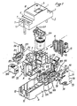
- la figure 1 représente une vue en perspective éclatée de l'appareil selon l'invention,
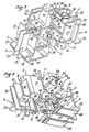
- la figure 2 représente la même vue en perspective de la pièce de structure,
- la figure 3 représente une autre vue en perspective de la pièce de structure;
- la figure 4 représente une vue en perspective de l'appareil avec son habillage,
- la figure 5 représente une vue en perspective de l'ensemble de l'appareil, l'habillage étant ôté,
- la figure 6 représente une coupe en élévation de l'appareil, par un plan traversant le mécanisme de serrure,
- la figure 7 représente une coupe transversale de l'appareil par un plan passant devant le relais de déclenchement différentiel,
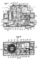
- la figure 8 représente une coupe transversale par un plan passant par l'axe de la manette, la manette étant ôtée,
- la figure 9 représente une coupe en élévation de l'appareil par un plan passant par l'axe de la bobine de déclenchement magnétique, et
- la figure 10 représente une vue en coupe selon un plan transversal perpendiculaire à celui de la figure précédente et passant par l'axe de la bobine de disjonction magnétique.
- FIG. 1 represents an exploded perspective view of the apparatus according to the invention,
- FIG. 2 represents the same perspective view of the structural part,
- Figure 3 shows another perspective view of the structural part;
- FIG. 4 represents a perspective view of the device with its covering,
- FIG. 5 represents a perspective view of the whole of the apparatus, the covering being removed,
- FIG. 6 represents a section in elevation of the device, by a plane passing through the lock mechanism,
- FIG. 7 represents a transverse section of the apparatus by a plane passing in front of the differential trip relay,
- FIG. 8 represents a cross section through a plane passing through the axis of the handle, the handle being removed,
- FIG. 9 represents a section in elevation of the device through a plane passing through the axis of the magnetic trip coil, and
- 10 shows a sectional view along a transverse plane perpendicular to that of the previous figure and passing through the axis of the magnetic disjunction coil.
L'appareil représenté est habillé par un boîtier réalisé sous forme de deux demi-boîtiers 1, 2, à savoir un demi-boîtier supérieur 1 et un demi-boîtier inférieur 2, les deux boîtiers étant raccordés au niveau d'une ligne de séparation 3. Le demi-boîtier inférieur 2 présente, de façon usuelle, des moyens d'accrochage 4, 5 sur un rail alors que le demi-boîtier supérieur 1 présente deux paires d'épaulements successifs 6, 7 et un sommet 8 muni d'un passage 9 pour le levier d'actionnement manuel du mécanisme. Les bords extrêmes du boîtier présentent chacun, dans le demi-boîtier inférieur 2, chaque fois deux ouvertures 10 autorisant respectivement l'accès aux différentes bornes à cage 12, 13 de l'appareil et les épaulements 7 présentent chacun deux passages 11 pour l'accès aux vis de borne respectives des cages.The device shown is covered by a box made in the form of two half-
A l'intérieur du boîtier, l'appareil est monté sur une pièce de structure centrale 20 réalisée par injection moulage. Cette pièce 20 présente une forme générale à peu près symétrique par rapport à un plan vertical médian que matérialise une cloison médiane 21. A faible distance de l'une des extrémités, la cloison médiane 21 se raccorde à une cloison transversale 22 au-delà de laquelle des cloisons dédoublées 23 définissent, avec la cloison transversale 22, deux zones de bornes A destinées à recevoir les bornes de l'appareil, ces zones de bornes étant limitées à la partie inférieure par de petites parois horizontales 25 s'étendant des cloisons dédoublées 23 et des cloisons transversales, pour recevoir et isoler les bornes 12 respectives.Inside the housing, the device is mounted on a central
La cloison 21 se poursuit, en direction de l'autre extrémité, peu après le milieu de l'appareil, par une seconde cloison transversale 26 à partir de laquelle s'étendent deux cloisons 27 se dirigeant d'abord parallèlement vers l'extrémité puis convergent de façon cylindrique pour former, avec un fond 28, une zone de mesure B susceptible de recevoir un agencement de tore de mesure différentielle. Dans la partie centrale de la zone B formant logement de tore se trouve un fût cylindrique 30 qui se raccorde, à la partie inférieure, à un prolongement de la cloison 21 passant sous le fond 28, lequel présente, en cet emplacement, de part et d'autre de ce prolongement de cloison 21, un passage en demi-lune 31.The
Les cloisons 27, de même que le prolongement de cloison 21, se raccordent à une paroi transversale 32 à partir de laquelle s'étendent des cloisons dédoublées 33 analogues aux cloisons 23 de façon à former deux autres zones de bornes A délimitées, à la partie inférieure, par des parois de fond 34 perpendiculaires aux parois 32 et 33 et analogues aux parois 25, de façon à recevoir et isoler les deux autres bornes 13.The
Deux zones de contact C sont délimitées vers la partie inférieure de la structure entre les parois 22 et 32. A leur partie supérieure, ces zones de contact C sont délimitées par les parties correspondantes du fond 28 et, pour l'une d'elles, par une paroi 36 s'étendant vers le centre à partir de la cloison 22 et environ à mi-hauteur de celle-ci, et pour l'autre, par une paroi 37 plus longue s'étendant environ à la même hauteur que la paroi 36, de l'autre côté de la cloison médiane 21.Two contact zones C are delimited towards the lower part of the structure between the
La cloison 21, au niveau des zones de contact C, présente une large échancrure 38, destinée au passage de la partie centrale du porte-contacts mobile, la cloison médiane 21 s'épaississant au-delà de l'échancrure 38 en une surépaisseur 39 formant un logement 40 pour le vissage d'une vis autotaraudeuse destinée à la fixation d'une pièce auxiliaire. Vers les coins latéraux inférieurs de la paroi 26, et en alignement avec l'échancrure 38, se trouvent deux portées en forme de demi-cercle 41, destinées à recevoir les tourillons de pivotement de la pièce porte-contacts mobile, les deux portées 41 étant réunies par une nervure de rigidification transversale 42.The
L'une des zones de contact C présente encore, à peu près dans le prolongement du fond 28, une cloison 43 dont la dimension latérale est bien inférieure à celle du fond 28 mais qui se prolonge par un retour 44 de sorte que subsiste, entre la cloison 43, le retour 44 et un prolongement de la portée 41, un passage 45 pour le levier de percussion du porte-contact mobile. Entre le retour 44 et la paroi 36, subsiste une échancrure 46.One of the contact zones C also has, roughly in the extension of the bottom 28, a
A la partie inférieure, les deux zones de contact C se trouvent délimitées, au regard des parois 36 et 37, par une paroi transversale inférieure 47 se raccordant, en son milieu, à la cloison 21 et s'arrêtant un peu avant l'emplacement du logement de vis 40. Vers l'extrémité de la pièce de structure 20, la paroi 47 présente, au niveau de chacun des deux logements formant les zones de contact C, un prolongement 48 ayant une section en forme de bec et se situant au-dessous et à un certaine distance des parois 25 des zones de bornes A des bornes 13.At the lower part, the two contact zones C are delimited, with respect to the
Au-dessus de l'échancrure 46 entre les parois 36 et 44, et à une assez grande distance, c'est-à-dire au niveau de la partie supérieure, en cet endroit, de la cloison médiane 21, s'étend'une cloison transversale 49 parallèle aux cloisons 36, 43 et 44, cette cloison 49 se poursuivant vers le haut par une cloison 50 se terminant presque au sommet de la cloison médiane 21, cette cloison 50 étant écartée d'une certaine distance de la partie de la cloison transversale 26 qui lui fait face. Les cloisons 49 et 50, perpendiculaires entre elles, se relient à une cloison latérale 51 présentant une fente 52 dans laquelle peut être introduite, et retenue élastiquement, une patte de fixation d'un relais.Above the
La face extérieure de la cloison 51 présente avantageusement plusieurs bossages ou tétons, à savoir un grand bossage 53 autour duquel peut s'enrouler un ressort en épingle dont une des branches vient s'immobiliser entre des tétons de réglage de ressort 54 et dont l'autre extrémité va venir s appuyer sur un prolongement latéral d'une pièce solidaire du plongeur de bobine de disjonction pour rappeler le plongeur en arrière.The outer face of the
La zone D située, d'un côté de la cloison médiane 21, entre les cloisons 22 et 26, d'une part, 36, 43, 44 et 49, d'autre part, forme ainsi la zone de déclenchement de disjonction électromagnétique destinée à recevoir notamment la bobine de disjonction avec son noyau plongeur et son percuteur.Zone D situated, on one side of the
La zone E située au-dessus de la cloison 49 et délimitée d'un côté par la cloison 51, et, du côté de la zone de mesure B, par la cloison 50, forme une autre zone de moyen de déclenchement de mécanisme recevant le relais de déclenchement différentiel.Zone E situated above the
La zone F située entre les cloisons 50 et 26, d'un côté de la cloison médiane 21, et en communication, à sa partie inférieure, avec la zone D, forme une zone de déclenchement de disjonction thermique destinée à recevoir une bilame.The zone F situated between the
Une zone de test G est située au-dessus de la zone de mesure B et est destinée à recevoir un ensemble de test.A test area G is located above the measurement area B and is intended to receive a test set.
Enfin, la zone de mécanisme H s'étend, de l'autre côté de la cloison médiane 21 par rapport aux zones D et F, et est délimitée par la cloison 21, la cloison 37 et, du côté de la zone de mesure, par la partie correspondante de la cloison transversale 26.Finally, the mechanism zone H extends, on the other side of the
Dans cette zone de mécanisme H, la cloison médiane 21 présente, à sa partie supérieure, et de l'autre côté de la zone F, un axe 58 destiné à recevoir l'organe de manoeuvre pivotant avec sa manette. Au-dessous de l'axe de manette 58 se trouve un axe de pivotement 59 sur lequel pivotera l'extrémité supérieure du levier déclencheur de mécanisme. Juste au-dessus d'un passage 60 faisant communiquer la zone de mécanisme H avec la zone de contact C sous-jacente, la cloison 21 présente un axe 61 sur lequel sera monté, de façon pivotante, le cliquet de mécanisme. Au-dessus de la cloison 37, la paroi 21 présente, d'une part, un axe 62 de pivotement d'un levier de déclenchement par relais et un axe 63 sur lequel sera montée une pièce pivotante intermédiaire de déclenchement coopérant avec le levier précité.In this mechanism zone H, the
Un certain nombre de passages sont prévus dans la cloison médiane 21, à savoir un passage 64 long et s' étendant vers le bas, faisant communiquer la zone de mécanisme H avec la zone de disjonction thermique F.A number of passages are provided in the
Au-dessus de la cloison 37 et sous les axes 62 et 63 se trouve pratiqué un passage 65 destiné à mettre en communication la zone de disjonction électromagnétique d'avec la zone de mécanisme H.Above the
Enfin, au niveau de l'axe 58 de l'organe de manoeuvre, la cloison 21 présente divers reliefs concentriques 67 destinés à recevoir un ressort de rappel d'organe de manoeuvre .Finally, at the
La pièce de structure 20 coopérera avec une pièce auxililaire réalisée, soit d'un seul tenant, soit en deux parties séparées. Cette pièce auxiliaire 70 présente d'une part, un flasque 71 destiné à venir clôturer latéralement la zone de mécanisme H, ce flasque présentant à sa partie supérieure une fente 72 analogue à la fente 52 pour recevoir l'autre patte du relais et présentant également un certain nombre de portées qui viendront s'aligner avec les axes 58, 62 et 63. Enfin, ce flasque 71 présente, vers sa partie inférieure, un retour 73 se raccordant selon un arrondi au reste du flasque de façon à venir compléter le palier 41 situé du côté de la zone de mécanisme H.The
La pièce 70 présente, par ailleurs, une partie inférieure 74 perpendiculaire au flasque 71 et présentant un passage central dans lequel pourra passer la vis 75 assurant l'assemblage entre la pièce auxiliaire 70 et la pièce de structure 20. Cette partie 74 présente deux renfoncements pour les ressorts de rappel des contacts mobiles et se poursuit, à l'opposé du flasque 71, par un retour 76 dont un prolongement 77 vient compléter le second palier 41.The
Dans l'exemple représenté et décrit, les volumes respectifs des différentes zones sont à peu près dans les proportions suivantes, par rapport au volume total interne disponible à l'intérieur du boîtier 1, 2 :
Les zones en question sont bien isolées les unes par rapport aux autres, la zone de mesure B étant éloignée des zones de contact et des zones magnétothermiques, la zone de relais E, également sensible, étant également éloignée des zones de contact.The zones in question are well insulated from one another, the measurement zone B being distant from the contact zones and the magnetothermal zones, the relay zone E, also sensitive, being also distant from the contact zones.
Lorsque les différents organes et pièces sont montés sur la pièce de structure 20, l'appareil, dépouillé de son boîtier 1, 2, présente l'aspect représenté sur la figure 5.When the various members and parts are mounted on the
Les bornes à cage 12, 13, avec leurs vis 14, sont montées dans les logements formant les quatre zones de borne A.The
Le tore de mesure 15 est inséré dans la zone de mesure B de forme cylindrique, autour du fût 30, et les conducteurs 16, en provenance des deux bornes 13 respectives, sont respectivement enroulés autour du tore 15 en passant centralement à l'intérieur du fût 30, de part et d'autre d'une cloison médiane de celui-ci, et à l'extérieur par-dessus les cloisons 27. L'un des conducteurs 16 se raccorde alors au prolongement 80 de la bobine électromagnétique 81 avec son noyau plongeur 82 et son percuteur 83, la bobine 81 étant enroulée en relation avec une armature fixe ferromagnétique et conductrice 84 en forme de cage contenant la bobine 81 et dont un bras, s'étendant dans la zone F, porte à son extrémité supérieure 85 la bilame 86 dont la position peut être réglée par l'intermédiaire d'une vis de réglage 87 portée par une autre extrémité 88, en regard, d'un second bras de l'armature. A son extrémité arrière, le plongeur 82 présente une pièce 89 dans laquelle peut venir en prise un ressort (non représenté) de rappel de plongeur et qui, d'autre part, présente une partie en forme de rampe destinée à coopérer avec le cliquet pour le déclenchement du mécanisme de serrure.The measuring
De façon avantageuse, l'ensemble composé par l'armature 84, la bobine 81, son noyau plongeur 82 avec le percuteur 83 ainsi que la bilame 86, est introduit latéralement sans difficulté dans la pièce de structure 20, c'est-à-dire dans les logements D et F qui communiquent entre eux.Advantageously, the assembly composed of the
Le porte-contacts pivotant 90 est monté, par ses tourillons 91, dans les portées 41 complétées par les prolongements respectifs 73 et 77 et porte, d'une façon en soi connue, les contacts mobiles 92 normalement écartés des contacts fixes 93, formés dans des lames 94, par de puissants ressorts de rappel 95 prenant appui dans les renfoncements prévus à cet effet dans la partie 74 de la pièce auxiliaire 70. L'agencement des contacts mobiles 92 dans le porte-contacts 90 est, d'une façon connue, tel que les ressorts 95 puissent aussi bien assurer la force nécessaire pour l'ouverture des contacts que la force d'appui des contacts mobiles 92 contre les contacts fixes 93 lorsqu'ils sont en position de fermeture. L'un des contacts mobiles 92 est relié, par une tresse conductrice 96, à celui des conducteurs 16 qui n'aboutit pas à la bobine de disjonction 81, l'autre contact mobile 92 étant relié, également par une tresse 97, à l'extrémité inférieure de la bilame 86 complétant ainsi le circuit.The pivoting
Le dispositif étant ainsi monté, un bras 98 du porte-contacts 90 traverse le passage 45 et se trouve donc, lorsque les contacts sont en position de fermeture, dans la trajectoire du percuteur 83. En fait, le bras 98, en position de contact ouvert, pénètre légèrement dans la zone de mesure B par le biais d'un passage 66 pratiqué dans la paroi 26 pour venir repousser une lame coudée de contact de test.The device being thus mounted, an
On voit, par ailleurs, que les chambres de coupure d'arc 99 usuelles ont trouvé place à 1 une des extrémités des zones de contact C, au-dessus des parties correpondantes de la paroi 47.It can be seen, moreover, that the usual arc-breaking
Le relais 100 d'interrupteur différentiel est logé dans sa zone E avec sa tige de relais orientée vers le bas. Il est maintenu en place par ses pattes latérales 101 s'encliquetant élastiquement dans les fentes 52, respectivement 72.The
Dans la zone de test G, la résistance de test 102 et le circuit imprimé de test 103 sont reçus dans leurs réceptacles respectifs pratiqués dans une pièce 104 dont le détail ne sera pas décrit, ladite pièce 104 étant clipée par deux pattes élastiques 105 dans des trous 68 pratiqués dans les parois 27, la pièce 104 étant ainsi superposée à la zone de mesure B. Le bouton de test 107 émerge au-dessus du sommet 8 du demi-boîtier 1 par un trou prévu à cet effet. Ce bouton permet d'ouvrir et de fermer un contact entre une lame coudée 106 et une extrémité de la résistance 102, l'autre branche de la lame 106, après un retour, se trouvant au niveau du bras 98 du porte-contact mobile 90 et dans la fin de sa trajectoire. Le circuit de test étant d'un principe connu, il ne sera pas décrit davantage.In the test zone G, the
Le mécanisme d'actionnement et de serrure est, par exemple, du type de celui décrit dans la demande de brevet européen EP-A-0. 143. 682. Sa fonction, en soi connue, est de permettre d'ouvrir ou de fermer manuellement les contacts en faisant basculer dans un sens ou dans un autre le porte-contacts mobile 90, de maintenir le porte-contacts en position basculée de contact par une serrure à genouillère et d'autoriser, en cas de déclenchement, la cassure de la genouillère pour permettre aux puissants ressorts 95 de décoller les contacts mobiles 92 loin des contacts fixes 93.The actuation and lock mechanism is, for example, of the type described in European patent application EP-A-0. 143. 682. Its function, known per se, is to allow the contacts to be opened or closed manually by tilting the
Ce mécanisme, dont le fonctionnement ne sera pas décrit en détail, comporte un organe de manoeuvre 110 pivotant autour de l'axe 58 et rappelé normalement en position correspondant à 1 ouverture des contacts par un ressort de rappel monté dans les reliefs 67, ledit organe de manoeuvre présentant une manette d'actionnement 111. Par un axe excentré par rapport à l'axe 58, la manette 111 est articulée à une bielle 112 elle-même articulée, à son extrémité inférieure, à l'extrémité supérieure d'une biellette 113. L'extrémité inférieure de celle-ci est articulée au porte-contacts mobile 90 en un emplacement excentré par rapport à l'axe des tourillons de celle-ci. L'axe 114 d'articulation entre la bielle 112 et la biellette 113 se prolonge latéralement pour pénétrer dans une rainure oblongue 115 située à l'extrémité d'un levier déclencheur 116 articulé par son extrémité supérieure à l'axe 59. A sa partie inférieure, au-delà de la rainure 115, le levier déclencheur 116 se termine par un bec 117 normalement empêché de s'échapper par la présence du bec complémentaire 118 d'un cliquet 119 articulé autour de l'axe 61 et normalement rappelé en position d'encliquetage, c'est-à-dire en sens horaire sur la figure 6, par un ressort de rappel de cliquet (non représenté). Ce cliquet présente, outre son bec 118, un bras allongé 120 se terminant par deux doigts transversaux dont l'un traverse le passage 65 pour coopérer avec la rampe que forme la pièce de plongeur 89, et l'autre va coopérer avec des moyens de déclenchement par le relais 100. Le cliquet 119 présente également un bras plus court 121 se terminant par un doigt transversal qui traverse le passage 64 pour coopérer avec la bilame 86.This mechanism, the operation of which will not be described in detail, comprises an operating
Si la bobine de disjonction 81 se trouve excitée, le plongeur 82 est déplacé brutalement vers la gauche (figure 9) et son percuteur 83 vient repousser violemment le bras 98 du porte-contacts mobile 90 pour provoquer son mouvement d'ouverture et assurer l'arrachage des contacts mobiles 92 et leur séparation d'avec les contacts fixes 93. Simultanément, la pièce 89 de plongeur vient repousser le doigt du grand bras 120 du cliquet 119, assurant le basculement du cliquet et la libération des becs respectifs 117, 118 et donc la cassure de la genouillère, autorisant le basculement du porte-contacts 90 vers sa position d'ouverture.If the
De même la déformation de la bilame 86 sous l'effet d'une surintensité provoque une poussée de la bilame sur le doigt du bras court 121 du cliquet 119, de sorte que le cliquet bascule, faisant casser la genouillère, et que les ressorts 95 repoussent les contacts mobiles 92 et le portecontacts 90 en position d'ouverture éloignée des contacts fixes 93.Similarly, the deformation of the
En cas d'actionnement par le relais 100, la tige de celui-ci, qui se déplace alors verticalement vers le bas, vient basculer un levier de déclenchement et de réarmement de relais 122 pivotant sur l'axe 62 et rappelé normalement en sens anti-horaire (figure 6) par un ressort de rappel. Ce levier 122 présente un court bras perpendiculaire 123 se terminant par un bec d'accrochage qui coopère avec un bec d'accrochage (non vu) d'une pièce pivotante intermédiaire de déclenchement 124 rappelée normalement en sens horaire (figure 6) autour de son axe 63 par un ressort convenable. Les becs ayant été dégagés l'un de l'autre par le basculement du levier 122 sous l'effet de la descente de la tige du relais 100, la pièce 124 tourne en sens horaire (figure 6) et repousse le doigt correspondant terminant le long bras 120 du cliquet 119, assurant également la cassure de la genouillère et l'ouverture des contacts. La pièce 124 présente avantageusement un long bras 125 qui assure sa remise en place lors du mouvement du mécanisme qui suit la cassure de la genouillère et qui est provoqué par l'action du ressort de rappel de l'organe de manoeuvre pivotant 110, mouvement qui ramène l'ensemble du mécanisme à sa position initiale de repos dans laquelle les contacts sont séparés, position représentée sur les figures 6 et 9.In the event of actuation by the
En se référant plus particulièrement à la figure 1, on voit que l'invention permet non seulement une répartion optimale des volumes disponibles mais également un montage particulièrement rationnel des différents constituants du dispositif.Referring more particularly to FIG. 1, it can be seen that the invention allows not only a distribution optimal available volumes but also a particularly rational assembly of the various components of the device.
Ainsi, on peut réaliser séparément l'ensemble magnétothermique avec la bobine 81 et la bilame 86, l'ensemble de test avec son support 104 ayant reçu tous les autres constituants, et un ensemble de mécanisme comprenant le mécanisme de genouillère et le porte-contacts mobile 90 avec ses contacts 92, de même que deux ensembles formés chacun par une borne 12, une lame 94 représentant le contact fixe 93 et la chambre de coupure d'arc 99.Thus, the magnetothermal assembly can be produced separately with the
Ces différents ensembles, de même que le relais 100, viennent se disposer par emboîtement dans leurs zones respectives. Il suffit ensuite de venir mettre en place la pièce auxiliaire 70 pour que le mécanisme se trouve monté dans sa position définitive.These different assemblies, as well as the
En dehors de ces opérations de montage simples, les seules opérations à réaliser sont, d'une part, l'enroulement des conducteurs 16, une fois le tore 15 mis en place et avant clipsage de l'ensemble de test, le soudage de l'une des extrémités des deux conducteurs 16 aux tresses respectives, le soudage de l'un de ces conducteurs 16 à l'extrémité d'une lame conductrice 126 se dirigeant vers l'une des chambres de coupure d'arc, la liaison des conducteurs issus du relais aux conducteurs provenant du tore et la soudure de l'une des deux extrémités de la résistance de test 102 aux conducteurs adéquats.Apart from these simple assembly operations, the only operations to be carried out are, on the one hand, the winding of the
Les différents éléments ainsi mis en place sont fermement maintenus par la pièce de structure centrale, aucune pièce et aucun conducteur n'étant en fait flottant. Il suffit alors, sans aucune précaution particulière, de venir habiller l'ensemble tel qu'on le voit sur la figure 5 à l'aide des deux demi-boîtiers 1, 2 et le dispositif est prêtThe various elements thus put in place are firmly held by the central structural part, no part and no conductor being in fact floating. It then suffices, without any particular precaution, to dress the assembly as seen in FIG. 5 using the two half-
Claims (26)
- A device for protecting electrical installations, comprising a modular casing (1, 2) and having conventional terminals (12, 13) for connection, a plurality of fixed contacts (93) cooperating with a plurality of moving contacts (92), mechanism means with a lock for manually displacing the moving contacts towards or away from the fixed contacts, the said mechanism means with a lock being mounted on a central structural member inside the casing and defining contact zones receiving one or a plurality of pivoting contact carriers (90) adapted to approach and move away from the movable contacts with the fixed contacts, a subjacent mechanism zone (H) adapted to contain the mechanism with the lock actuating the contact carrier(s) and also a zone (D, E, F) separate from the aforementioned, adapted to receive a differential triggering relay, characterised in that the said central structural member (20) produced in monoblock fashion and in a manner known per se comprising a median partition (21) comprises beyond transverse partitions (22, 23) between which the said median partition partially extends, partitioned terminal zones (A) receiving respective connecting terminals (12, 13) of the device, and in that the said central structural member (20) has a measuring zone (B) adapted to receive a differential detection core or other measuring means such as electronic detection elements, the said zones (B), suitably partitioned to ensure electrical separation, forming the means of mounting and supporting the elements which are contained therein.
- A device according to Claim 1, characterised in that the structural member (20) comprises walls (26, 27, 32) defining a substantially cylindrical housing forming the measuring zone (B).
- A device according to one of Claims 1 and 2, characterised in that the contact zones (C) comprise a wall (74) on each of which a contact restoring spring (95) bears.
- A device according to any one of Claims 2 and 3, characterised in that extending from one of the said transverse walls (32) are two walls (27) defining a substantially cylindrical housing forming the said measuring zone (B) and ending in a new transverse wall (26) extending on either side of the median wall.
- A device according to Claim 4, characterised in that the said transverse wall (26) has bearing elements (41) for journals of movable contact carriers, towards the bottom part of the said wall (26), a notch (38) being made in the median partition (21) for passage of the said movable contact carrying member, walls (36, 37) extending from the other transverse partition (22) and at right-angles to the median partition (21) in order to define below them contact zones (C) and above them respectively a zone of electromagnetic triggering means (D) and a mechanism zone (H), the said median partition (21) having in the mechanism zone (H) a plurality of pivots or journals (58, 59, 61, 62, 63) for the pivoting members of the mechanism whereas on the other side of the mechanism zone (H), the space is made up by a zone of bimetallic thermal trigger means (F) likewise bounded by the transverse partition (26) separating it from the measuring zone (B) and by another transverse wall (50) extending at right-angles to the median partition above the electromagnetic trigger means zone (D) and forming, with other respectively perpendicular walls (49, 51) a part of the zone of relay triggering means (E), the said zones of electromagnetic triggering means (D) and thermal triggering means (H) communicating with the mechanism zone (H) by respective passages (64, 65).
- A device according to any one of Claims 1 to 5, characterised in that the measuring zone is adapted to form a housing receiving a core (15).
- A device according to any one of Claims 1 to 6, characterised in that it comprises three zones of triggering means, viz a zone (D) intended to receive electromagnetic triggering means for circuit-breaking, a zone (F) intended to receive a thermal triggering means such as a bimetallic strip and a zone (E) adapted to receive a differential triggering means such as a differential make-or-break relay.
- A device according to any one of Claims 1 to 7, characterised in that the structural member (20) has one single contact triggering mechanism zone (H), particularly one with a knee-type lock, adapted to contain a single mechanism adapted to be actuated at different locations by the triggering means contained in a plurality of mechanism triggering zones (D, E, F).
- A device according to any one of Claims 1 to 8, characterised in that the structural member (20) is designed so that a supplementary zone (G) is left which forms a test zone which is capable of receiving test means.
- A device according to any one of Claims 1 to 9, characterised in that the measuring zone (B) extends over the entire width available towards one of the two ends of the device close to the zones (A) receiving the terminals.
- A device according to any one of Claims 1 to 10, characterised in that a test zone (G) is provided above the measuring zone (B).
- A device according to Claim 11, characterised in that the test zone (G) receives a test assembly which can be clipped onto a wall of the measuring zone (B).
- A device according to any one of Claims 1 to 12, characterised in that a zone of mechanism triggering means (E) receiving a differential triggering relay connected electrically to the measuring zone (B) is situated far from the measuring zones (B) and contact zones (C).
- A device according to any one of Claims 1 to 13, characterised in that the triggering mechanism zone with the lock is elongated between the top and the bottom of the device on one and the same side of a median partition (21) of the structural member (20).
- A device according to any one of Claims 1 to 14, characterised in that a triggering means zone (D) containing electromagnetic circuit-breaking means, is situated between the contact zone (C) and the mechanism triggering zone (E) receiving a relay (100) and in communication with the contact triggering mechanism zone (H) which has the lock.
- A device according to any one of Claims 1 to 15, characterised in that the triggering means zone (D) receiving electromagnetic circuit-breaking means communicates with a thermal triggering means zone (F) with a bimetallic strip in such a way that a magnetothermal assembly containing the said circuit-breaking means and the said bimetallic strip is able to be introduced in one piece into the said zones within the structural member (20).
- A device according to all of Claims 1 to 16, characterised in that the structural member (20) is adapted to define: two contact zones (C) extending parallel on either side of a median plane (21) to the bottom part of the apparatus; a lock triggering mechanism zone (H) situated above one of the said contact zones (C); a mechanism triggering means zone (D) adapted to receive electromagnetic circuit-breaking means and situated above the other contact zone (C); a mechanism triggering means zone (E) adapted to receive a relay extending over the said electromagnetic triggering means zone (D) and above a part of the said mechanism zone (H); another triggering means zone (F) adapted to receive a bimetallic strip disposed above that of the contact zones (C) which is situated under the said electromagnetic triggering means zone (D) and extending alongside the said zone (E) receiving the relay means; a measuring zone (B) extending above the two contact zones (C) and separated from the said zone of relay triggering means (E) by the mechanism triggering zone (F) receiving the bimetallic strip and a part of the mechanism zone (H); a test zone (G) situated above the said measuring zone (B), and four terminal zones (A) extending at the two ends of the device, on either side of the assembly formed by the other zones.
- A device according to any one of the preceding Claims, characterised in that the structural member (20) is on one of its sides supplemented by an auxiliary member (70) likewise extending under the bottom part of the structural member.
- A device according to Claim 18, characterised in that the said auxiliary member (70) has extensions (73, 77) which complete the said bearings (41) for the journals of the movable contact carriers (20).
- A device according to one of Claims 18 or 19, characterised in that the said complementary member (70) has bearings aligned with the journals (58, 59, 60, 61, 62, 63) offered by the said median partition (21) in the mechanism zone (H).
- A device according to any one of Claims 18 to 20, characterised in that the said auxiliary member (70) has in the bottom part of the structural member (20) an arm (74) provided with reinforcements to accommodate restoring springs (95) for the movable contacts.
- A device according to any one of Claims 18 to 21, characterised in that the said auxiliary member (70) has towards its upper end a click-stop engaging slot (72) and in that a lateral wall (51) of the zone (E) of relay triggering means has a similar slot (52) the said slots (52, 72) making it possible by click-stop engagement to position relay fixing lugs.
- A device according to Claim 22, characterised in that the said lateral wall (51) of the said zone (E) has on the outside bosses (53, 54) which cooperate with a restoring spring of an electromagnetic plunger.
- A device according to any one of the preceding Claims, characterised in that it comprises a test support means (104) accommodating test elements and adapted to be clipped onto the measuring zone (B) by lugs (105).
- A device according to any one of the preceding Claims, characterised in that the casing (1, 2) forms a housing around the device mounted on its structural member (20).
- A device according to Claim 25, characterised in that the said casing is formed of two half-casings (1, 2) one of which carries the engaging means (4) while the other (1) has passages (9, 10) to accommodate the actuating or test buttons or levers.
Priority Applications (1)
| Application Number | Priority Date | Filing Date | Title |
|---|---|---|---|
| AT88403298T ATE88834T1 (en) | 1988-01-20 | 1988-12-23 | PROTECTION DEVICE FOR ELECTRICAL INSTALLATIONS. |
Applications Claiming Priority (2)
| Application Number | Priority Date | Filing Date | Title |
|---|---|---|---|
| FR8800597A FR2626105B1 (en) | 1988-01-20 | 1988-01-20 | ELECTRICAL PROTECTION APPARATUS |
| FR8800597 | 1988-01-20 |
Publications (2)
| Publication Number | Publication Date |
|---|---|
| EP0325071A1 EP0325071A1 (en) | 1989-07-26 |
| EP0325071B1 true EP0325071B1 (en) | 1993-04-28 |
Family
ID=9362461
Family Applications (1)
| Application Number | Title | Priority Date | Filing Date |
|---|---|---|---|
| EP88403298A Expired - Lifetime EP0325071B1 (en) | 1988-01-20 | 1988-12-23 | Protection device for electrical installations |
Country Status (4)
| Country | Link |
|---|---|
| EP (1) | EP0325071B1 (en) |
| AT (1) | ATE88834T1 (en) |
| DE (1) | DE3880659T2 (en) |
| FR (1) | FR2626105B1 (en) |
Cited By (1)
| Publication number | Priority date | Publication date | Assignee | Title |
|---|---|---|---|---|
| RU2457568C2 (en) * | 2007-06-29 | 2012-07-27 | Шнейдер Электрик Эндюстри Сас | Electric commutation device having additional electric function |
Families Citing this family (14)
| Publication number | Priority date | Publication date | Assignee | Title |
|---|---|---|---|---|
| FR2686453B1 (en) * | 1992-01-17 | 1994-04-08 | Legrand | DIFFERENTIAL SWITCH. |
| DE4211916A1 (en) * | 1992-04-09 | 1993-10-14 | Abb Patent Gmbh | Installation device |
| DE4244606C2 (en) * | 1992-12-31 | 1995-08-31 | Kloeckner Moeller Gmbh | Electromagnetic switching device |
| US5446431A (en) * | 1994-04-28 | 1995-08-29 | Square D Company | Ground fault module conductors and base therefor |
| IT1283162B1 (en) * | 1996-07-15 | 1998-04-07 | Gewiss Spa | AUTOMATIC MODULAR AND COMPONABLE ELECTRIC SWITCH, WITH OPTIMIZATION OF THE SPACES USED |
| IT1283161B1 (en) * | 1996-07-15 | 1998-04-07 | Gewiss Spa | MOVING CONTACT ACTIVATION KINEMATICS, PARTICULARLY FOR AUTOMATIC ELECTRIC SWITCHES |
| IT1292339B1 (en) * | 1997-05-20 | 1999-01-29 | Gewiss Spa | MOVING CONTACT ACTIVATION KINEMATICS PARTICULARLY FOR AUTOMATIC ELECTRIC SWITCHES |
| AT502415B1 (en) * | 2003-08-19 | 2007-03-15 | Moeller Gebaeudeautomation Kg | TEST PUSHBUTTON, CONNECTION CONNECTION FOR A TEST SWITCH, PROTECTIVE SWITCH AND METHOD FOR PRODUCING A PROTECTIVE SWITCH |
| DE102004034859A1 (en) * | 2004-07-19 | 2006-02-16 | Siemens Ag | Protection device in narrow construction |
| NL1027343C2 (en) * | 2004-10-26 | 2006-04-27 | Eaton Electric Nv | Switch is for breaking current circuit and comprises housing with mechanical switch assembly for operation of contacts, short circuit current protection device for breaking current circuit in event of sudden very high circulating current |
| FR3016078A1 (en) * | 2013-12-27 | 2015-07-03 | Legrand France | ELECTRICAL EQUIPMENT WITH MODULAR FORMAT |
| EP3718126A1 (en) * | 2017-12-01 | 2020-10-07 | Hager-Electro SAS | Modular electrical switching device |
| FR3121273A1 (en) * | 2021-03-26 | 2022-09-30 | Schneider Electric Industries Sas | Electrical protection device and electrical panel comprising such an electrical protection device |
| FR3133267A1 (en) * | 2022-03-07 | 2023-09-08 | Hager-Electro Sas | Electrical protective device |
Family Cites Families (4)
| Publication number | Priority date | Publication date | Assignee | Title |
|---|---|---|---|---|
| US3143627A (en) * | 1960-04-15 | 1964-08-04 | Gen Electric | Multipole circuit breaker with three part insulating casing |
| DE1256775B (en) * | 1966-07-23 | 1967-12-21 | Stotz Kontakt Gmbh | Multipole electrical circuit breaker with overcurrent, short-circuit and fault current release |
| DE2915091C2 (en) * | 1979-04-12 | 1981-07-30 | Siemens AG, 1000 Berlin und 8000 München | Residual current circuit breaker |
| FR2569901B1 (en) * | 1984-09-06 | 1986-12-26 | Hager Electro | IMPROVEMENTS TO AUTOMATIC SWITCHES, IN PARTICULAR TO DIFFERENTIAL SWITCHES AND CIRCUIT BREAKERS |
-
1988
- 1988-01-20 FR FR8800597A patent/FR2626105B1/en not_active Expired - Fee Related
- 1988-12-23 EP EP88403298A patent/EP0325071B1/en not_active Expired - Lifetime
- 1988-12-23 DE DE88403298T patent/DE3880659T2/en not_active Expired - Lifetime
- 1988-12-23 AT AT88403298T patent/ATE88834T1/en not_active IP Right Cessation
Cited By (1)
| Publication number | Priority date | Publication date | Assignee | Title |
|---|---|---|---|---|
| RU2457568C2 (en) * | 2007-06-29 | 2012-07-27 | Шнейдер Электрик Эндюстри Сас | Electric commutation device having additional electric function |
Also Published As
| Publication number | Publication date |
|---|---|
| EP0325071A1 (en) | 1989-07-26 |
| DE3880659T2 (en) | 1993-11-25 |
| FR2626105B1 (en) | 1990-06-15 |
| FR2626105A1 (en) | 1989-07-21 |
| ATE88834T1 (en) | 1993-05-15 |
| DE3880659D1 (en) | 1993-06-03 |
Similar Documents
| Publication | Publication Date | Title |
|---|---|---|
| EP0325071B1 (en) | Protection device for electrical installations | |
| EP0591074B1 (en) | Moulded case circuit breaker with auxiliary contacts | |
| EP0619590B1 (en) | Multipole circuit breaker with modular assembly | |
| EP0501844B1 (en) | Protection circuit breaker having a thermo-magnetic sub-assembly | |
| EP0196241A1 (en) | Single pole and neutral differential circuit breaker | |
| FR2712731A1 (en) | Thermo-magnetic trip unit for circuit breaker in molded case and circuit breaker using such a unit. | |
| FR2643503A1 (en) | CONTACT DEVICE HAVING PROTECTED SWITCHES | |
| FR2495825A1 (en) | SYNCHRONIZED MULTIPOLAR CIRCUIT BREAKER, CONSISTING OF MULTIPLE ASSEMBLIES AND INCLUDING A MUTUAL LINK ROD | |
| EP0008989B1 (en) | Low voltage electric circuit breaker with auxiliary actuating units | |
| FR2720545A1 (en) | Heavy gauge circuit breaker and mounting of trip unit and auxiliary devices in such a circuit breaker. | |
| EP0501885B1 (en) | Circuit breaker | |
| EP0403358A1 (en) | Neutral and phase circuit breaker | |
| EP0649158B1 (en) | Differential protection block with cable passage | |
| FR2521773A1 (en) | SMALL CONTACTOR EQUIPPED WITH A REMOVABLE AUXILIARY SWITCH SUBASSEMBLY | |
| FR2674370A1 (en) | PROTECTIVE SWITCHING APPARATUS ACCOUPABLE TO A CONTROL MODULE AND / OR A SIGNALING MODULE. | |
| FR2513006A1 (en) | MODULAR MULTIPLE POLE SWITCHING DEVICE | |
| EP0325501B1 (en) | Automatic switches, in particular differential switches and circuit breakers | |
| EP0275750B1 (en) | Bipolar differential interrupter with fault indicator | |
| FR2684231A1 (en) | Auxiliary apparatus of electrical circuit breakers | |
| EP0209433B1 (en) | Mobile contacts support, in particular for a protection circuit breaker | |
| FR2478367A1 (en) | LOCKING DEVICE FOR A CIRCUIT BREAKER | |
| EP0033671B1 (en) | Low-voltage multi-pole differential switch | |
| EP0602024B1 (en) | Operating mechanism for a multipolar fault-current protective switch with a rotary crossbar | |
| EP0136290B1 (en) | Automatic protection switch with visible sectioning and hand reset | |
| EP2743947B1 (en) | Support shaft of the movable contacts in an electric current breaking apparatus, and current breaking apparatus comprising same, in particular a coupling breaker |
Legal Events
| Date | Code | Title | Description |
|---|---|---|---|
| PUAI | Public reference made under article 153(3) epc to a published international application that has entered the european phase |
Free format text: ORIGINAL CODE: 0009012 |
|
| AK | Designated contracting states |
Kind code of ref document: A1 Designated state(s): AT BE CH DE ES FR GB GR IT LI NL |
|
| 17P | Request for examination filed |
Effective date: 19900119 |
|
| 17Q | First examination report despatched |
Effective date: 19911218 |
|
| GRAA | (expected) grant |
Free format text: ORIGINAL CODE: 0009210 |
|
| AK | Designated contracting states |
Kind code of ref document: B1 Designated state(s): AT BE CH DE ES FR GB GR IT LI NL |
|
| PG25 | Lapsed in a contracting state [announced via postgrant information from national office to epo] |
Ref country code: AT Effective date: 19930428 Ref country code: ES Free format text: THE PATENT HAS BEEN ANNULLED BY A DECISION OF A NATIONAL AUTHORITY Effective date: 19930428 Ref country code: NL Effective date: 19930428 Ref country code: GR Free format text: LAPSE BECAUSE OF FAILURE TO SUBMIT A TRANSLATION OF THE DESCRIPTION OR TO PAY THE FEE WITHIN THE PRESCRIBED TIME-LIMIT Effective date: 19930428 |
|
| REF | Corresponds to: |
Ref document number: 88834 Country of ref document: AT Date of ref document: 19930515 Kind code of ref document: T |
|
| ITF | It: translation for a ep patent filed |
Owner name: ING. C. GREGORJ S.P.A. |
|
| REF | Corresponds to: |
Ref document number: 3880659 Country of ref document: DE Date of ref document: 19930603 |
|
| GBT | Gb: translation of ep patent filed (gb section 77(6)(a)/1977) |
Effective date: 19930510 |
|
| NLV1 | Nl: lapsed or annulled due to failure to fulfill the requirements of art. 29p and 29m of the patents act | ||
| PG25 | Lapsed in a contracting state [announced via postgrant information from national office to epo] |
Ref country code: LI Effective date: 19931231 Ref country code: CH Effective date: 19931231 Ref country code: BE Effective date: 19931231 |
|
| PLBE | No opposition filed within time limit |
Free format text: ORIGINAL CODE: 0009261 |
|
| STAA | Information on the status of an ep patent application or granted ep patent |
Free format text: STATUS: NO OPPOSITION FILED WITHIN TIME LIMIT |
|
| 26N | No opposition filed | ||
| BERE | Be: lapsed |
Owner name: S.A. HAGER ELECTRO Effective date: 19931231 |
|
| REG | Reference to a national code |
Ref country code: CH Ref legal event code: PL |
|
| REG | Reference to a national code |
Ref country code: GB Ref legal event code: IF02 |
|
| PGFP | Annual fee paid to national office [announced via postgrant information from national office to epo] |
Ref country code: GB Payment date: 20021217 Year of fee payment: 15 |
|
| PG25 | Lapsed in a contracting state [announced via postgrant information from national office to epo] |
Ref country code: GB Free format text: LAPSE BECAUSE OF NON-PAYMENT OF DUE FEES Effective date: 20031223 |
|
| GBPC | Gb: european patent ceased through non-payment of renewal fee |
Effective date: 20031223 |
|
| PGFP | Annual fee paid to national office [announced via postgrant information from national office to epo] |
Ref country code: IT Payment date: 20071221 Year of fee payment: 20 |
|
| PGFP | Annual fee paid to national office [announced via postgrant information from national office to epo] |
Ref country code: FR Payment date: 20071217 Year of fee payment: 20 |
|
| PGFP | Annual fee paid to national office [announced via postgrant information from national office to epo] |
Ref country code: DE Payment date: 20071211 Year of fee payment: 20 |