EP0325024B1 - Überwachung des Wirkungsgrades von Flüssigkeitspumpen - Google Patents
Überwachung des Wirkungsgrades von Flüssigkeitspumpen Download PDFInfo
- Publication number
- EP0325024B1 EP0325024B1 EP88309425A EP88309425A EP0325024B1 EP 0325024 B1 EP0325024 B1 EP 0325024B1 EP 88309425 A EP88309425 A EP 88309425A EP 88309425 A EP88309425 A EP 88309425A EP 0325024 B1 EP0325024 B1 EP 0325024B1
- Authority
- EP
- European Patent Office
- Prior art keywords
- thermocouple
- sensing means
- pump
- diaphragm
- monitoring
- Prior art date
- Legal status (The legal status is an assumption and is not a legal conclusion. Google has not performed a legal analysis and makes no representation as to the accuracy of the status listed.)
- Expired - Lifetime
Links
- 239000007788 liquid Substances 0.000 title claims abstract description 14
- 238000012544 monitoring process Methods 0.000 title claims abstract description 9
- 238000000034 method Methods 0.000 claims abstract description 13
- RYGMFSIKBFXOCR-UHFFFAOYSA-N Copper Chemical compound [Cu] RYGMFSIKBFXOCR-UHFFFAOYSA-N 0.000 claims abstract description 7
- 229910045601 alloy Inorganic materials 0.000 claims abstract description 6
- 239000000956 alloy Substances 0.000 claims abstract description 6
- 229910052802 copper Inorganic materials 0.000 claims abstract description 6
- 239000010949 copper Substances 0.000 claims abstract description 6
- 229920001651 Cyanoacrylate Polymers 0.000 claims abstract description 4
- 239000000853 adhesive Substances 0.000 claims abstract description 3
- 230000001070 adhesive effect Effects 0.000 claims abstract description 3
- 229920002379 silicone rubber Polymers 0.000 claims abstract description 3
- 239000004945 silicone rubber Substances 0.000 claims abstract description 3
- 238000009413 insulation Methods 0.000 claims description 8
- 239000000463 material Substances 0.000 claims description 5
- 239000007767 bonding agent Substances 0.000 claims description 4
- -1 alkyl cyano acrylate Chemical compound 0.000 claims description 2
- 229910001006 Constantan Inorganic materials 0.000 abstract description 3
- 239000004830 Super Glue Substances 0.000 abstract description 2
- 230000001681 protective effect Effects 0.000 abstract description 2
- 230000008878 coupling Effects 0.000 abstract 1
- 238000010168 coupling process Methods 0.000 abstract 1
- 238000005859 coupling reaction Methods 0.000 abstract 1
- 238000005259 measurement Methods 0.000 description 3
- 239000003570 air Substances 0.000 description 2
- 239000002184 metal Substances 0.000 description 2
- 229910052751 metal Inorganic materials 0.000 description 2
- 239000012080 ambient air Substances 0.000 description 1
- 238000009529 body temperature measurement Methods 0.000 description 1
- 239000004020 conductor Substances 0.000 description 1
- 238000010276 construction Methods 0.000 description 1
- 230000006866 deterioration Effects 0.000 description 1
- 238000010586 diagram Methods 0.000 description 1
- 230000001771 impaired effect Effects 0.000 description 1
- 238000009434 installation Methods 0.000 description 1
- 239000011810 insulating material Substances 0.000 description 1
- 238000012423 maintenance Methods 0.000 description 1
- 238000004519 manufacturing process Methods 0.000 description 1
- 238000005065 mining Methods 0.000 description 1
- 238000012986 modification Methods 0.000 description 1
- 230000004048 modification Effects 0.000 description 1
- 238000011160 research Methods 0.000 description 1
- 238000012360 testing method Methods 0.000 description 1
- 238000012546 transfer Methods 0.000 description 1
Images
Classifications
-
- G—PHYSICS
- G01—MEASURING; TESTING
- G01L—MEASURING FORCE, STRESS, TORQUE, WORK, MECHANICAL POWER, MECHANICAL EFFICIENCY, OR FLUID PRESSURE
- G01L3/00—Measuring torque, work, mechanical power, or mechanical efficiency, in general
- G01L3/26—Devices for measuring efficiency, i.e. the ratio of power output to power input
-
- G—PHYSICS
- G01—MEASURING; TESTING
- G01K—MEASURING TEMPERATURE; MEASURING QUANTITY OF HEAT; THERMALLY-SENSITIVE ELEMENTS NOT OTHERWISE PROVIDED FOR
- G01K1/00—Details of thermometers not specially adapted for particular types of thermometer
- G01K1/14—Supports; Fastening devices; Arrangements for mounting thermometers in particular locations
- G01K1/143—Supports; Fastening devices; Arrangements for mounting thermometers in particular locations for measuring surface temperatures
-
- G—PHYSICS
- G01—MEASURING; TESTING
- G01K—MEASURING TEMPERATURE; MEASURING QUANTITY OF HEAT; THERMALLY-SENSITIVE ELEMENTS NOT OTHERWISE PROVIDED FOR
- G01K3/00—Thermometers giving results other than momentary value of temperature
- G01K3/08—Thermometers giving results other than momentary value of temperature giving differences of values; giving differentiated values
- G01K3/14—Thermometers giving results other than momentary value of temperature giving differences of values; giving differentiated values in respect of space
Definitions
- This invention relates to a method of monitoring the efficiency of liquid pumps by a measurement of temperature differentials.
- Thermometric pump efficiency monitoring has been proposed on the basis that the temperature rise across a pump is a measure of energy loss in the pump, whilst the pressure or head rise across the pump measures the useful work.
- Such a proposal is described by A Whillier, Mining Research Laboratory, Chamber of Mines of South Africa, Africa, Africa ("SITE TESTING OF PUMPS” IME London 1972, pages 209-217), who draws attention to the need for several centimetres thickness of thermal insulation over thermocouples in contact with pipe surfaces.
- the values of temperature rise are small, and temperature measurements have hitherto been impaired by shortcomings in the thermal insulation of the thermocouples from the environment immediately surrounding the pipes to which they are attached.
- the traditional means of sensing accurately the temperature of a liquid in a pipe involves the use of a thermowell which allows the temperature sensor to project into the liquid.
- the fitting of thermowells, especially to working plant, can be both costly and inconvenient.
- a method of monitoring the efficiency of a liquid pump comprising the steps of securing temperature sensing means in close thermal contact with outside surfaces of suction and discharge conduits of the pump respectively, providing thermal insulation over each sensing means, and using an electrical output from the sensing means as a measure of the temperature rise across the pump, characterised in that the thermal insulation over each sensing means comprises a diaphragm enclosing a still-air pocket around the sensing means.
- thermocouples having junctions of which the temperature coefficients match to within a thousandth of a degree Centigrade are provided by using wire elements from the same respective alloy batches.
- the heat transfer coefficient between flowing liquid and a pipe wall inside surface is of the order of one thousand times greater than that between the pipe wall outside surface and ambient air.
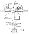
- the liquid pump 10 has suction and discharge conduits 11 and 12 respectively, these being metal pipes.
- thermocouple is constructed having first and second junctions 13, 14 (popularly termed “cold” and “hot” junctions) disposed on opposite sides of the pump. Each thermocouple junction is in close thermal contact with the associated conduit or pipe 11 or 12. Thus, each thermocouple junction is bonded to the cleaned pipe surface by means of a low-viscosity bonding agent such as an alkyl cyano acrylate (popularly known as "superglue").
- a low-viscosity bonding agent such as an alkyl cyano acrylate (popularly known as "superglue”).
- the electrical conductors or wire elements of the junctions 13, 14 are led to a junction box 15 which is turn is interconnected with voltage-measuring instrumentation 16.
- thermocouple junction 13 14 Thermal insulation is provided over each thermocouple junction 13, 14.
- an air-tight still-air pocket 17 is established around each junction by means of a cupped diaphragm 18 made from a compliant material such as a silicone rubber.
- the periphery or rim of each diaphragm 18 is attached to the pipe wall by means of an adhesive.
- Each junction/diaphragm arrangement is further enclosed by a protective box cover 19 which may conveniently be strapped in position on the pipe 11 or 12.
- Each box cover 19 carries an electrical terminal assembly 20 to provide a convenient means of establishing electrical connections between the junctions 13, 14 and the junction box 15.
- thermocouple junctions 13, 14 must closely match, to within a thousandth of a degree Centigrade. Such close matching is attained by ensuring that the wire elements used in the construction of the thermocouple are from the same respective alloy batches.
- a suitable thermocouple is copper/constantan, as shown in Fig. 2. All of the constantan wire material is from the same alloy batch; and all of the copper material (at least between the junction box 15 and the thermocouple junctions 13, 14) is also from the same alloy or melt batch. As is also shown in Fig.
- thermocouple 15 the copper elements of the thermocouple are used in connections with the instrumentation 16 thus avoiding further dissimilar metal junctions since copper is virtually universally used in the manufacture of electrical equipment.
- both the junction box 15 and the instrumentation 16 may be wrapped in thermal insulating material as indicated by reference numerals 21 and 22.
- thermocouple arrangement as above described be permanently provided for a single pump installation, and the measuring instrumentation 16 be connected as and when required for a monitoring operation. It will be evident that the system is relatively cheap and easy to install.
- thermocouples each as described above may be employed in "tandem" for example in cases where the head rise across the pump is less than 10 bar.
- tandem arrangement is indicated in Fig. 1 by broken lines 23.
Landscapes
- Physics & Mathematics (AREA)
- General Physics & Mathematics (AREA)
- Jet Pumps And Other Pumps (AREA)
- Reciprocating Pumps (AREA)
- Sampling And Sample Adjustment (AREA)
- Measuring Fluid Pressure (AREA)
Claims (9)
- Verfahren zur Überwachung des Wirkungsgrades von Flüssigkeitspumpen (10), umfassend die Schritte des Befestigens von Temperatur-Abtast-Mitteln (13, 14) in engem Wärmekontakt mit den äußeren Oberflächen von Ansaug- bwz. Auslaufrohrleitungen (11, 12) der Pumpe (10), Ausrüsten mit Wärmeisolierung (17, 18, 19) über jedem Aufnahmemittel, und Nutzung des elektrischen Ausgangs der Aufnahmemittel als ein Maß für den Temperaturanstieg über der Pumpe (10), dadurch gekennzeichnet, daß die Wärmeisolierung über jedem Aufnahmemittel (13, 14) eine Membran (18) aufweist, welche eine Tasche mit stillstehender Luft (17) um die Aufnahmemittel (13, 14) herum einschließt.
- Verfahren nach Anspruch 1, dadurch gekennzeichnet, daß die Membran (18) eine becherförmige Membran aus einem nachgiebigen Material ist.
- Verfahren nach Anspruch 2, dadurch gekennzeichnet, daß das nachgiebige Material ein Silikongummi ist.
- Verfahren nach einem der Ansprüche 1 bis 3, dadurch gekennzeichnet, daß der Umfang der Membran (18) an die jeweiligen Rohrleitungen (11, 12) mittels Klebemittel angefügt ist, so daß die Tasche (17) innerhalb der Membran (18) luftdicht ist.
- Verfahren nach einem der vorhergehenden Ansprüche, dadurch gekennzeichnet, daß die Temperatur-Abtast-Mittel Thermoelementanschlüsse (13, 14) enthalten, und die miteinander korrespondierenden Drahtelemente der Thermoelemente aus derselben Legierungsgruppe sind.
- Verfahren nach Anspruch 5, dadurch gekennzeichnet, daß ein Draht des Thermoelementes aus Kupfer besteht und für den Anschluß an ein Spannungsmeßgerät (16) genutzt wird.
- Verfahren nach Anspruch 5 oder 6, dadurch gekennzeichnet, daß die Thermoelementanschlüsse (13, 14) auf den Rohrleitungen (11, 12) mittels eines Haftmittels sicher befestigt sind.
- Verfahren nach Anspruch 7, dadurch gekennzeichnet, daß das Haftmittel vor dem Abbinden eine Flüssigkeit mit niedriger Viskosität ist, um eine optimale Dichtheit des thermalen Kontaktes zwischen Anschluß und Rohrleitungsoberfläche zu erzielen.
- Verfahren nach Anspruch 8, dadurch gekennzeichnet, daß das Haftmittel ein Alcyl-Cyano-Acrylat ist.
Priority Applications (1)
| Application Number | Priority Date | Filing Date | Title |
|---|---|---|---|
| AT88309425T ATE91786T1 (de) | 1987-10-10 | 1988-10-07 | Ueberwachung des wirkungsgrades von fluessigkeitspumpen. |
Applications Claiming Priority (2)
| Application Number | Priority Date | Filing Date | Title |
|---|---|---|---|
| GB8723840 | 1987-10-10 | ||
| GB878723840A GB8723840D0 (en) | 1987-10-10 | 1987-10-10 | Monitoring efficiency of liquid pumps |
Publications (3)
| Publication Number | Publication Date |
|---|---|
| EP0325024A2 EP0325024A2 (de) | 1989-07-26 |
| EP0325024A3 EP0325024A3 (en) | 1990-05-16 |
| EP0325024B1 true EP0325024B1 (de) | 1993-07-21 |
Family
ID=10625125
Family Applications (1)
| Application Number | Title | Priority Date | Filing Date |
|---|---|---|---|
| EP88309425A Expired - Lifetime EP0325024B1 (de) | 1987-10-10 | 1988-10-07 | Überwachung des Wirkungsgrades von Flüssigkeitspumpen |
Country Status (4)
| Country | Link |
|---|---|
| EP (1) | EP0325024B1 (de) |
| AT (1) | ATE91786T1 (de) |
| DE (1) | DE3882511T2 (de) |
| GB (1) | GB8723840D0 (de) |
Families Citing this family (3)
| Publication number | Priority date | Publication date | Assignee | Title |
|---|---|---|---|---|
| RU2395723C1 (ru) * | 2009-05-15 | 2010-07-27 | Открытое акционерное общество "Татнефть" им. В.Д. Шашина | Способ эксплуатации насосного агрегата в процессе закачки жидкости в пласт |
| US20110168266A1 (en) * | 2010-01-14 | 2011-07-14 | Brett Fiora | Closed System Water Conservation Apparatus |
| CN105673473A (zh) * | 2016-03-28 | 2016-06-15 | 昆明理工大学 | 一种隔膜泵单向阀多源信息采集装置及安装方法 |
Family Cites Families (3)
| Publication number | Priority date | Publication date | Assignee | Title |
|---|---|---|---|---|
| US3903743A (en) * | 1973-02-13 | 1975-09-09 | Hans Gunter Noller | Temperature compensated thermometer utilizing thermocouples |
| US4130019A (en) * | 1977-06-09 | 1978-12-19 | Nitschke John Stephen | Self-compensating thermocouple reading circuit |
| US4217761A (en) * | 1978-09-28 | 1980-08-19 | Cornaire James L | Heat pump output indicator |
-
1987
- 1987-10-10 GB GB878723840A patent/GB8723840D0/en active Pending
-
1988
- 1988-10-07 EP EP88309425A patent/EP0325024B1/de not_active Expired - Lifetime
- 1988-10-07 AT AT88309425T patent/ATE91786T1/de active
- 1988-10-07 DE DE88309425T patent/DE3882511T2/de not_active Expired - Fee Related
Also Published As
| Publication number | Publication date |
|---|---|
| EP0325024A3 (en) | 1990-05-16 |
| GB8723840D0 (en) | 1987-11-11 |
| EP0325024A2 (de) | 1989-07-26 |
| DE3882511T2 (de) | 1994-02-17 |
| DE3882511D1 (de) | 1993-08-26 |
| ATE91786T1 (de) | 1993-08-15 |
Similar Documents
| Publication | Publication Date | Title |
|---|---|---|
| EP1216403B1 (de) | Temperatur-management in einem druckwandler | |
| CN110243487A (zh) | 具有改善的热传导的热通量传感器 | |
| CN101896804A (zh) | 具有热学管理的压力变送器的直接安装装置 | |
| EP3633337A1 (de) | Oberfläche-temperaturmessanordnung | |
| US4238957A (en) | Pyrometric sheath and process | |
| US20110162736A1 (en) | Autonomous temperature transmitter | |
| EP0325024B1 (de) | Überwachung des Wirkungsgrades von Flüssigkeitspumpen | |
| CN101126653A (zh) | 低热阻热质量流量传感器 | |
| US8790008B2 (en) | Device for measuring the temperature of a substrate | |
| US4722026A (en) | Thermal protection apparatus | |
| CN115183890B (zh) | 温度测量设备 | |
| US4682898A (en) | Method and apparatus for measuring a varying parameter | |
| US4573806A (en) | Thermocouple isolation block system | |
| CN217980587U (zh) | 光纤光栅表面温度传感器 | |
| US3979229A (en) | Temperature measuring device having a deformable temperature sensing head thereof | |
| EP3430358B1 (de) | Anordnung und verfahren zur bestimmung einer messwert für ein stromkabel | |
| US3954508A (en) | High temperature thermocouple probe | |
| SU1040351A1 (ru) | Устройство дл измерени температуры преимущественно подземной части трубопровода | |
| HUP0104369A2 (hu) | Berendezés reaktorban lévő hűtőközeg szintjének meghatározására | |
| JP2513892B2 (ja) | 強磁界用温度センサ | |
| US2732416A (en) | Robertson | |
| CN223064713U (zh) | 一种真空测温用热电偶装置 | |
| JPH07104214B2 (ja) | 気密端子付シース型熱電対 | |
| SU857735A1 (ru) | Термоэлектрический термометр | |
| EP2894450A1 (de) | Sensor zur Messung von Flüssigkeitsvariablen in einer korrosiven Umgebung |
Legal Events
| Date | Code | Title | Description |
|---|---|---|---|
| PUAI | Public reference made under article 153(3) epc to a published international application that has entered the european phase |
Free format text: ORIGINAL CODE: 0009012 |
|
| AK | Designated contracting states |
Kind code of ref document: A2 Designated state(s): AT BE CH DE ES FR GB GR IT LI LU NL SE |
|
| PUAL | Search report despatched |
Free format text: ORIGINAL CODE: 0009013 |
|
| AK | Designated contracting states |
Kind code of ref document: A3 Designated state(s): AT BE CH DE ES FR GB GR IT LI LU NL SE |
|
| 17P | Request for examination filed |
Effective date: 19901112 |
|
| RAP1 | Party data changed (applicant data changed or rights of an application transferred) |
Owner name: SCOTTISH DEVELOPMENT AGENCY |
|
| RAP1 | Party data changed (applicant data changed or rights of an application transferred) |
Owner name: SCOTTISH DEVELOPMENT AGENCY |
|
| 17Q | First examination report despatched |
Effective date: 19920430 |
|
| RAP1 | Party data changed (applicant data changed or rights of an application transferred) |
Owner name: SCOTTISH ENTERPRISE |
|
| RIN1 | Information on inventor provided before grant (corrected) |
Inventor name: MURRAY, BRIAN GILCHRIST |
|
| GRAA | (expected) grant |
Free format text: ORIGINAL CODE: 0009210 |
|
| AK | Designated contracting states |
Kind code of ref document: B1 Designated state(s): AT BE CH DE ES FR GB GR IT LI LU NL SE |
|
| PG25 | Lapsed in a contracting state [announced via postgrant information from national office to epo] |
Ref country code: IT Free format text: LAPSE BECAUSE OF FAILURE TO SUBMIT A TRANSLATION OF THE DESCRIPTION OR TO PAY THE FEE WITHIN THE PRE;WARNING: LAPSES OF ITALIAN PATENTS WITH EFFECTIVE DATE BEFORE 2007 MAY HAVE OCCURRED AT ANY TIME BEFORE 2007. THE CORRECT EFFECTIVE DATE MAY BE DIFFERENT FROM THE ONE RECORDED.SCRIBED TIME-LIMIT Effective date: 19930721 Ref country code: AT Effective date: 19930721 Ref country code: CH Effective date: 19930721 Ref country code: LI Effective date: 19930721 Ref country code: GR Free format text: LAPSE BECAUSE OF FAILURE TO SUBMIT A TRANSLATION OF THE DESCRIPTION OR TO PAY THE FEE WITHIN THE PRESCRIBED TIME-LIMIT Effective date: 19930721 Ref country code: ES Free format text: THE PATENT HAS BEEN ANNULLED BY A DECISION OF A NATIONAL AUTHORITY Effective date: 19930721 Ref country code: BE Effective date: 19930721 |
|
| REF | Corresponds to: |
Ref document number: 91786 Country of ref document: AT Date of ref document: 19930815 Kind code of ref document: T |
|
| REF | Corresponds to: |
Ref document number: 3882511 Country of ref document: DE Date of ref document: 19930826 |
|
| REG | Reference to a national code |
Ref country code: CH Ref legal event code: PL |
|
| PG25 | Lapsed in a contracting state [announced via postgrant information from national office to epo] |
Ref country code: LU Free format text: LAPSE BECAUSE OF NON-PAYMENT OF DUE FEES Effective date: 19931031 |
|
| ET | Fr: translation filed | ||
| PLBE | No opposition filed within time limit |
Free format text: ORIGINAL CODE: 0009261 |
|
| STAA | Information on the status of an ep patent application or granted ep patent |
Free format text: STATUS: NO OPPOSITION FILED WITHIN TIME LIMIT |
|
| REG | Reference to a national code |
Ref country code: GB Ref legal event code: 732E |
|
| 26N | No opposition filed | ||
| REG | Reference to a national code |
Ref country code: FR Ref legal event code: TP |
|
| NLS | Nl: assignments of ep-patents |
Owner name: DEVELOPMENT ENGINEERING INTERNATIONAL LIMITED TE A |
|
| EAL | Se: european patent in force in sweden |
Ref document number: 88309425.2 |
|
| PGFP | Annual fee paid to national office [announced via postgrant information from national office to epo] |
Ref country code: FR Payment date: 19951010 Year of fee payment: 8 |
|
| PGFP | Annual fee paid to national office [announced via postgrant information from national office to epo] |
Ref country code: SE Payment date: 19951017 Year of fee payment: 8 |
|
| PGFP | Annual fee paid to national office [announced via postgrant information from national office to epo] |
Ref country code: DE Payment date: 19951023 Year of fee payment: 8 |
|
| PGFP | Annual fee paid to national office [announced via postgrant information from national office to epo] |
Ref country code: NL Payment date: 19951024 Year of fee payment: 8 |
|
| PG25 | Lapsed in a contracting state [announced via postgrant information from national office to epo] |
Ref country code: SE Effective date: 19961008 |
|
| PG25 | Lapsed in a contracting state [announced via postgrant information from national office to epo] |
Ref country code: NL Effective date: 19970501 |
|
| PG25 | Lapsed in a contracting state [announced via postgrant information from national office to epo] |
Ref country code: FR Effective date: 19970630 |
|
| NLV4 | Nl: lapsed or anulled due to non-payment of the annual fee |
Effective date: 19970501 |
|
| PG25 | Lapsed in a contracting state [announced via postgrant information from national office to epo] |
Ref country code: DE Effective date: 19970701 |
|
| EUG | Se: european patent has lapsed |
Ref document number: 88309425.2 |
|
| REG | Reference to a national code |
Ref country code: FR Ref legal event code: ST |
|
| REG | Reference to a national code |
Ref country code: GB Ref legal event code: IF02 |
|
| PGFP | Annual fee paid to national office [announced via postgrant information from national office to epo] |
Ref country code: GB Payment date: 20071003 Year of fee payment: 20 |
|
| REG | Reference to a national code |
Ref country code: GB Ref legal event code: PE20 Expiry date: 20081006 |
|
| PG25 | Lapsed in a contracting state [announced via postgrant information from national office to epo] |
Ref country code: GB Free format text: LAPSE BECAUSE OF EXPIRATION OF PROTECTION Effective date: 20081006 |