EP0324928A2 - Continously variable transmission control - Google Patents
Continously variable transmission control Download PDFInfo
- Publication number
- EP0324928A2 EP0324928A2 EP88119843A EP88119843A EP0324928A2 EP 0324928 A2 EP0324928 A2 EP 0324928A2 EP 88119843 A EP88119843 A EP 88119843A EP 88119843 A EP88119843 A EP 88119843A EP 0324928 A2 EP0324928 A2 EP 0324928A2
- Authority
- EP
- European Patent Office
- Prior art keywords
- control
- valve
- pressure
- clutch
- electro
- Prior art date
- Legal status (The legal status is an assumption and is not a legal conclusion. Google has not performed a legal analysis and makes no representation as to the accuracy of the status listed.)
- Granted
Links
Images


Classifications
-
- B—PERFORMING OPERATIONS; TRANSPORTING
- B60—VEHICLES IN GENERAL
- B60W—CONJOINT CONTROL OF VEHICLE SUB-UNITS OF DIFFERENT TYPE OR DIFFERENT FUNCTION; CONTROL SYSTEMS SPECIALLY ADAPTED FOR HYBRID VEHICLES; ROAD VEHICLE DRIVE CONTROL SYSTEMS FOR PURPOSES NOT RELATED TO THE CONTROL OF A PARTICULAR SUB-UNIT
- B60W30/00—Purposes of road vehicle drive control systems not related to the control of a particular sub-unit, e.g. of systems using conjoint control of vehicle sub-units, or advanced driver assistance systems for ensuring comfort, stability and safety or drive control systems for propelling or retarding the vehicle
- B60W30/18—Propelling the vehicle
-
- B—PERFORMING OPERATIONS; TRANSPORTING
- B60—VEHICLES IN GENERAL
- B60W—CONJOINT CONTROL OF VEHICLE SUB-UNITS OF DIFFERENT TYPE OR DIFFERENT FUNCTION; CONTROL SYSTEMS SPECIALLY ADAPTED FOR HYBRID VEHICLES; ROAD VEHICLE DRIVE CONTROL SYSTEMS FOR PURPOSES NOT RELATED TO THE CONTROL OF A PARTICULAR SUB-UNIT
- B60W10/00—Conjoint control of vehicle sub-units of different type or different function
- B60W10/04—Conjoint control of vehicle sub-units of different type or different function including control of propulsion units
-
- B—PERFORMING OPERATIONS; TRANSPORTING
- B60—VEHICLES IN GENERAL
- B60W—CONJOINT CONTROL OF VEHICLE SUB-UNITS OF DIFFERENT TYPE OR DIFFERENT FUNCTION; CONTROL SYSTEMS SPECIALLY ADAPTED FOR HYBRID VEHICLES; ROAD VEHICLE DRIVE CONTROL SYSTEMS FOR PURPOSES NOT RELATED TO THE CONTROL OF A PARTICULAR SUB-UNIT
- B60W10/00—Conjoint control of vehicle sub-units of different type or different function
- B60W10/10—Conjoint control of vehicle sub-units of different type or different function including control of change-speed gearings
- B60W10/101—Infinitely variable gearings
-
- B—PERFORMING OPERATIONS; TRANSPORTING
- B60—VEHICLES IN GENERAL
- B60W—CONJOINT CONTROL OF VEHICLE SUB-UNITS OF DIFFERENT TYPE OR DIFFERENT FUNCTION; CONTROL SYSTEMS SPECIALLY ADAPTED FOR HYBRID VEHICLES; ROAD VEHICLE DRIVE CONTROL SYSTEMS FOR PURPOSES NOT RELATED TO THE CONTROL OF A PARTICULAR SUB-UNIT
- B60W30/00—Purposes of road vehicle drive control systems not related to the control of a particular sub-unit, e.g. of systems using conjoint control of vehicle sub-units, or advanced driver assistance systems for ensuring comfort, stability and safety or drive control systems for propelling or retarding the vehicle
- B60W30/18—Propelling the vehicle
- B60W30/1819—Propulsion control with control means using analogue circuits, relays or mechanical links
-
- F—MECHANICAL ENGINEERING; LIGHTING; HEATING; WEAPONS; BLASTING
- F16—ENGINEERING ELEMENTS AND UNITS; GENERAL MEASURES FOR PRODUCING AND MAINTAINING EFFECTIVE FUNCTIONING OF MACHINES OR INSTALLATIONS; THERMAL INSULATION IN GENERAL
- F16H—GEARING
- F16H61/00—Control functions within control units of change-speed- or reversing-gearings for conveying rotary motion ; Control of exclusively fluid gearing, friction gearing, gearings with endless flexible members or other particular types of gearing
- F16H61/66—Control functions within control units of change-speed- or reversing-gearings for conveying rotary motion ; Control of exclusively fluid gearing, friction gearing, gearings with endless flexible members or other particular types of gearing specially adapted for continuously variable gearings
- F16H61/662—Control functions within control units of change-speed- or reversing-gearings for conveying rotary motion ; Control of exclusively fluid gearing, friction gearing, gearings with endless flexible members or other particular types of gearing specially adapted for continuously variable gearings with endless flexible members
- F16H61/66254—Control functions within control units of change-speed- or reversing-gearings for conveying rotary motion ; Control of exclusively fluid gearing, friction gearing, gearings with endless flexible members or other particular types of gearing specially adapted for continuously variable gearings with endless flexible members controlling of shifting being influenced by a signal derived from the engine and the main coupling
- F16H61/66259—Control functions within control units of change-speed- or reversing-gearings for conveying rotary motion ; Control of exclusively fluid gearing, friction gearing, gearings with endless flexible members or other particular types of gearing specially adapted for continuously variable gearings with endless flexible members controlling of shifting being influenced by a signal derived from the engine and the main coupling using electrical or electronical sensing or control means
-
- F—MECHANICAL ENGINEERING; LIGHTING; HEATING; WEAPONS; BLASTING
- F16—ENGINEERING ELEMENTS AND UNITS; GENERAL MEASURES FOR PRODUCING AND MAINTAINING EFFECTIVE FUNCTIONING OF MACHINES OR INSTALLATIONS; THERMAL INSULATION IN GENERAL
- F16H—GEARING
- F16H61/00—Control functions within control units of change-speed- or reversing-gearings for conveying rotary motion ; Control of exclusively fluid gearing, friction gearing, gearings with endless flexible members or other particular types of gearing
- F16H61/12—Detecting malfunction or potential malfunction, e.g. fail safe; Circumventing or fixing failures
Definitions
- the invention relates to control gearbox control, particularly for a motor vehicle.
- the invention relates to an electric control gear control for a passenger car.
- the passenger car in particular uses a continuously variable mechanical transmission with a pair of primary and secondary disks, and that is connected by a thrust link belt.
- the present invention has set itself the goal of providing an electro-hydraulic control gear control, in particular according to the preamble of claim 1, such that all modes of operation of the vehicle can be safely controlled.
- the invention aims in particular to provide the design of the variable-speed transmission control in such a way that there are no dangers for the operation of the vehicle if the power supply fails.
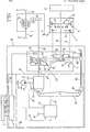
- Fig. 1 the engine of a motor vehicle is shown schematically, in particular a car.
- the car is specially designed for front-wheel drive and transverse installation of the engine.
- the input means 1 which can be actuated by the driver of the passenger car and which serve to influence the transmission of the torque of the engine (drive machine) 3 to the wheels 2.
- the motor 3 is connected to the wheels 2 via a clutch device 4, an electrohydraulically controlled continuously variable mechanical transmission 5 and a drive device 6.
- the electro-hydraulically controlled continuously variable mechanical transmission 5 has a continuously variable mechanical transmission 7 and an electro-hydraulic control 8 for the transmission 7.
- the electro-hydraulic control 8 in turn has control electronics 9 and an electro-hydraulic valve arrangement 10.
- an output shaft 29 of the motor 3 is connected to the clutch 13 of the clutch device 4.
- the clutch 13 has a forward clutch 11 and a reverse clutch 12 in a known manner.
- a planetary gear 16 having a planet gear carrier 14 and a ring gear 15 is provided in the coupling device 4.
- the continuously variable mechanical transmission 7 has a pair of primary disks 18 and a pair of secondary disks 19, connected by a thrust link belt 20.
- the pair of primary disks 18 comprises a first or left primary disk 21 and a second or right primary disk 22.
- the pair of secondary disks 19 has a first or left secondary disk 23 and a second or right secondary disk 24.
- the first primary disk 21 forms, in a manner not shown in detail, a primary cylinder 25 which acts on the pressure medium Impact over a line 45 to be described, the axially movable first primary plate 21 can move according to arrow 26 with respect to the second axially immovable primary plate 22.
- the second axially movable secondary disk 24 forms a secondary cylinder 27 which, when acted upon by pressure medium supplied by a line 49, can cause a movement according to arrow 28 with respect to the axially stationary first primary disk 23.
- the clutch device 4 transmits the torque to the pair of primary disks 18 via the output 31 or output 30.
- an output shaft 32 connects the pair of secondary disks 19 to a reduction gear 33, which in turn is connected to a differential gear 34.
- the differential gear 34 drives the wheels 2 via drive shafts 35 and 36.
- the electro-hydraulic control (control system) 8 essentially consists of the control electronics 9 and the electro-hydraulic valve arrangement 10, which are connected to the primary cylinder 25 and the secondary cylinder 27 via the hydraulic lines 45 and 49 already mentioned.
- a hydraulic pump 40 is also provided, which sucks the hydraulic pressure medium, for example hydraulic oil, from a tank 41 and delivers it via a line 42 to a main oil pressure valve 43 (hereinafter also a system pressure valve or contact pressure valve) and to a primary valve or transmission valve 44. Both valves 43, 44 are also connected to tank 41.
- the translation valve 44 has an electrical drive which can be actuated by the microprocessor 9 via the electrical line 47.
- the contact pressure valve 43 can be actuated by a lever 55 to deliver more or less contact pressure to the secondary cylinder 27.
- the lever 55 is connected via a connection 48 as well as slide 56, spring 57 and sensor 58 to the axially movable first primary disk, so that the contact pressure of the pair of secondary disks 19 can be changed corresponding to the ratio given by the pair of primary disks 18.
- the control electronics 9 is connected via a line 50 to a driving speed sensor 59.
- the microprocessor 9 processes other input values that can be entered by the driver via lines 51, 52, 53 and 54.
- the microprocessor 9 can of course record and process other values.
- the planetary gear carrier 14 When starting the vehicle, as already mentioned, the planetary gear carrier 14 is connected directly to the one primary disk by means of the forward clutch 11, or else the ring gear 15 is braked by means of the reverse clutch 12, so that the direction of rotation is reversed. In both cases, the primary disk pair 18 is driven in a ratio of 1: 1, i.e. with the engine speed.
- the thrust link belt in the primary disc pair 18 runs on the smallest radius, the maximum gear ratio "low” corresponding to the first gear of a manual transmission is obtained.
- the first primary disk 21 must be displaced towards the axially stationary primary disk 22. This is done by supplying precisely predetermined amounts of oil to the primary cylinder 25 via line 45 through the transmission valve 44. If the thrust link belt 20 runs on the primary disk belt 18 on the largest possible radius, then the maximum translation "high” is reached. Between these two extreme band positions "low” and “high” any translation is possible by moving the first primary disc 21 according to arrow 26.
- the second or right secondary disk 24 is also tracked.
- the secondary cylinder 27 is acted upon by the pressure valve 43 via line 49 in order to generate the required pretensioning force and to enable a slip-free torque transmission, specifically in accordance with the axial position of the first primary disk 21 sensed by lever 55 and elements 56, 58 and 57.
- the system or main oil pressure must be controlled in such a way that the necessary clamping forces are always present on the secondary disks 23 and 24 so that the tension of the pusher belt is reached. This is done by means of the contact pressure valve 43 mentioned.
- the third main function is to provide a continuously variable transmission control, using the accelerator pedal position and the engine speed, which are provided as control signals.
- While a conventional, hydraulically controlled transmission control allows only one characteristic curve in the engine map, (as described in the above-mentioned magazine “Antriebstechnik” 24 (1985) No. 2, p. 49ff) in the arrangement according to FIG. 1 to obtain optimal fuel consumption selected gear ratios are adjusted so that the engine is operated at its best operating points.
- an "economy” (E) and a "sport” (S) program can be provided.
- the driver can, for example, via the input means 1 and z. B. enter the lines 53, 54 in the microprocessor 9 information that the "E" or the "S" program is selected.
- These programs are stored in the control electronics 9 and are therefore taken into account in the control.
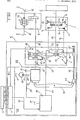
- FIG. 2 shows a first exemplary embodiment of a control gear control 81 with an electrohydraulic valve arrangement.
- the transmission valve 44 which is actuated by the control electronics 9 via an electrical line 47 (cf. FIG. 1) and a servomotor, is replaced by a transmission control valve 62, specifically a pilot-operated, electrohydraulic valve.
- the transmission control valve 62 according to the invention is a pilot-controlled electrohydraulic proportional 3-way valve with position feedback and external control pressure intervention.
- the transmission control valve 62 permits a quantity adjustment that is insensitive to disturbance variables in two flow directions.
- the translation valve 62 is designed according to the invention such that it adjusts itself automatically in the event of a power failure and adjusts the continuously variable mechanical transmission 7 to maximum translation. Otherwise, the structure is as in FIG. 1, with an electrical line 63 connecting the valve 62 to the control electronics 9.
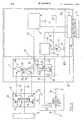
- FIG. 3 shows a further exemplary embodiment of an electrohydraulically controlled continuously variable mechanical transmission.
- This transmission differs in its electrohydraulic control (control gear control) 82 from the control gear control 81 according to FIG. 2, in particular 81, in that the electro-hydraulic valve arrangement 102 is changed compared to the valve arrangement 101.
- the contact pressure valve is designed as a pilot-controlled electrohydraulic proportional pressure relief valve 64.
- the valve 64 is actuated by the microprocessor 9 via an electrical signal line 65.
- the microprocessor 9 in Fig. 3 takes over its inputs 51 to 54 provide information with regard to the translation set by the primary disk pair 18 and supplies a corresponding electrical signal via line 65 in order to provide the contact pressure on the secondary disk pair 19 corresponding to the existing translation.
- the embodiment according to FIG. 3 thus uses an electrohydraulic valve both for transmission control and for regulating the contact pressure on the pair of secondary disks 19.
- the electro-hydraulic valves are preferably pilot-controlled.
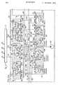
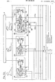
- FIGS. Fig. 4 shows this embodiment using circuit symbols.
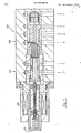
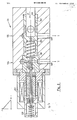
- Fig. 5 shows the valves in detail.
- FIGS. 6 to 13 describe preferred exemplary embodiments of the valves used in FIG. 5.
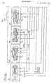
- FIG. 4 is constructed in principle like the exemplary embodiment according to FIG. 3, and accordingly the motor 3, the coupling device 4, the drive shaft 29, the output shafts 30, 31 and the continuously variable mechanical transmission 7 can be seen the control electronics (microprocessor) 9 is shown and the electro-hydraulic control is not designated 82 in this embodiment, but 83.
- a cooler 73 and a clutch cooler 74 are shown.
- gear selector 70 which is connected to the clutch device 4 for manual control via lines 71 (for the reverse clutch) and line 72 (for the forward clutch).
- the basic difference between the electrohydraulic control gear control 83 and the electrohydraulic one Regulating transmission control 82 consists in that, in addition to the two valves 62 and 64 controlled by the microprocessor 9, a clutch control valve 86, likewise controlled by the microprocessor 9 via a line 66, is provided.
- the three valves 62, 64 and 86 are designed such that they assume safe positions for the operation of the vehicle in the event of a power failure.
- the electro-hydraulic control gear control 83 has a clutch safety valve 87 and a speed detection safety valve 88. Furthermore, according to the invention, a safety valve 90 is provided in addition to a lubricating oil pressure control valve 89. There is also a cooler valve 91.
- the transmission control valve 62 has a first consumer connection 186, a first tank connection 187, a second tank connection 287, a first pump connection 188, a second consumer connection 189, a third tank connection 387 and a second consumer connection 190.
- the clutch control valve 86 has a first consumer connection 587, a second consumer connection 687 and a pump connection 191.
- the clutch control valve 86 has a first consumer connection 787, a second consumer connection 192, a pump connection 193 and a third consumer connection 687.
- the clutch safety valve 87 has a first consumer connection 94, a second consumer connection 95, a third consumer connection 96 and a tank connection 187 on.
- the speed detection safety valve 88 has a first consumer connection 196, a first tank connection 287, a second consumer connection 97, a second consumer connection 98 and a second tank connection 387.
- the lubricating oil pressure control valve 89 has a consumer connection 99, a pump connection 100 and a tank connection 87.
- the safety valve 90 has a first consumer connection 106, a second consumer connection 107, a pump connection 108 and a tank connection 187.
- the cooler valve 91 has a first consumer connection 109, a second consumer connection 110, a third consumer connection 887 and a tank connection 287.
- the hydraulic lines shown in FIG. 4 are provided in detail for connecting the valves.
- the transmission control valve 62 is connected with its first consumer connection 186 to a line 118, which in turn is connected to the continuously variable mechanical transmission 7, namely the first (primary) pair of pulleys.
- the pump connections 188 and 190 are connected to the control line 42 supplied with pressure medium by the pump 40.
- the second consumer connection 189 is connected to a line 113, which in turn is connected to the first consumer connection 94 of the clutch safety valve 87 and the first consumer connection 196 of the speed detection safety valve 88.
- the first connection 587 of the contact pressure valve 64 is present Line 114; the latter is connected via line 75 to the clutch cooler 74 and then to the tank 41.
- the consumer connection 687 of the valve 64 is connected via a line 116 to the consumer connection 99 of the lubricating oil pressure control valve 89.
- Line 116 is also connected to line 78 leading to the lubricating oil circuit.
- the pump connection 191 of the valve 64 is connected to the control line 42 and via a line 42 C to the third consumer connection 98 of the speed detection safety valve 88.
- the clutch valve 86 is connected to line 114 via connection 787 and to line 114 via connection 687.
- the consumer connection 192 of the valve 86 is connected via line 115 to the consumer connection 96 of the clutch safety valve 87.
- the pump connection 193 is connected to the control line 42.
- the consumer connection 94 of the clutch safety valve 87 is connected via line 113 to connection 189 of the valve 62 and connection 196 of the valve 88.
- the port 95 of the valve 87 is connected to the cooler 73 via line 76.
- Port 96 of valve 87 is connected via line 115 to port 192 of valve 86.
- the tank port 187 is finally connected to the tank.
- the first consumer connection 196 is connected to the line 113, the first and second tank connections 287 and 387 lead to the tank and the second consumer connection 97 is connected to the first consumer connection 106 of the safety valve 90 via a line 117.
- the third consumer connection 98 of the valve 88 is connected via line 42 C to the line 42 and thus to the pump 40.
- the lubricating oil pressure control valve 89 is finally connected with its consumer connection 99 via line 116 to the connection 687 of the valve 64.
- the pump connection 100 is connected to line 42 and the tank connection 87 is connected to the tank.
- the second consumer connection 107 is connected to line 118 a, while the pump connection 108 is connected to line 42.
- the tank connector 187 is connected to the tank.
- the first consumer connection 109 is connected to line 118 a
- the second consumer connection 110 is connected to line 119, which is connected to line 77 of the cooler 73.
- port 887 communicates with clutch cooler 74 via line 75, while tank port 287 is connected directly to the tank.
- the transmission control valve 62 is of two stages and has a first or pilot stage 122 and a main stage 123. 5 shows the de-energized state in the upper half of the valve representations and the excited state at the bottom. Furthermore, the control variable Q or P is shown in FIG. 5 for the valves 62, 64 and 86 depending on the excitation current I. The dependence of the pressure on the two consumer outlets is illustrated for valve 89.
- a spring 127 is arranged between the piston of the pilot valve and the main valve.
- the piston of the pilot valve is also under the influence of a spring 126 and the influence of the excitation winding 125.
- the main valve 123 is biased by a spring 128 into the position a shown.
- the pressure at 189 can act on the one hand on the piston of the main valve via a check valve 129 and on the other hand act on the piston of the pilot valve via a throttle D5 in the same way as the spring 126.
- a two-edge slide pilot control and a two-edge slide main piston are used.
- the task of the transmission control valve is to carry out the transmission control by means of a continuous cone pulley adjustment in two directions.
- the system pressure control valve 64 has a pilot stage 134 and a main stage 135.
- a pilot-operated electrohydraulic proportional pressure relief valve with single-edge spool pilot and single-edge spool main stage.
- the pilot stage 134 has an excitation magnet 137 with a spring 139 acting opposite to it.
- the main stage has a spring 138 and a throttle 136.
- the system pressure control valve 64 allows a continuous change in the contact pressure of the link chain 20 against the conical disks. This is done hydraulically by means of a pressure control, whereby the maximum control pressure results as an emergency function in the event of a power failure.
- the clutch control valve 86 is a pilot-controlled electrohydraulic proportional pressure control valve with a single-edge slide pilot 142 and a double-edge slide main stage 143.
- the pilot stage 142 has an electromagnet 147 and a spring 146 counteracting it.
- the main stage provides a piston under the pressure of a spring 145 and also a throttle 144.
- the clutch control valve 86 provides a smooth engagement and disengagement of the drive clutch and implements this hydraulically by means of a pressure control. Maximum pressure is provided as an emergency function in the event of a power failure, i.e. the clutch is closed.
- the clutch safety valve 87 can assume two positions a and b and is biased into position a by a spring 151.
- a nozzle D3 is located between ports 94 and 187 in the manner shown.
- the speed detection safety valve 88 has the two stages 154 and 155. There are two switching states a and b provided, a spring 156 biasing the valve toward switching state a.
- the lubricating oil pressure control valve 89 is a conventional pressure control valve 59 which is loaded by a spring 160.
- the safety valve 90 has a two-way valve 161 and, on the one hand, is loaded by a spring 163 and, on the other hand, is connected to a preload valve 162, a throttle D4 also being present in the manner shown.
- the two-way valve as such is designated by 161.
- the cooler valve 91 has a four / two-way valve 165 and is biased by a spring 166 in the state shown.
- FIG. 5 represents the same situation as FIG. 4. However, the quantities occurring there are indicated at the connections of the various valves in Fig. 5, e.g. Pressure P2 at port 191, etc. Some of the port reference numerals of FIG. 4 have also been transferred to FIG. 5 for valve 62.
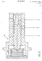
- a first version of a transmission control valve 62 is shown in section, and Fig. 7 shows a second version of the transmission control valve 62 '.
- the ratio control valve 62 is shown for unexcited magnetic fields 125, i.e. there is a clear safety position in the event of a power failure: the main spool is in the "P-A, connection open” position, i.e. the maximum gear ratio results.
- FIG. 6 shows the first embodiment variant in which the main piston is supported on a spring 128.
- 7 shows the second variant, in which the main piston is supported against pressure.
- the implementation is carried out by a second piston with half the nominal area, guided in the main piston, pressurization through bore with inlet pressure.
- the following advantage results: Simultaneous increase in control pressure and actuating forces with the inlet pressure.
- interference compensation by comparing the force between coupling spring 127 and magnetic force.
- Axial tolerance compensation by adjusting screw 701 on the magnet.
- Axial tolerance insensitivity through fine control pockets Better resolution, better characteristic reproducibility with cast control edges.
- Characteristic curve symmetry characteristic curve adjustment by varying the number of fine control pockets. Filtering against very fine contamination of the cone pulley abrasion.
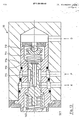
- FIG. 8 shows the system pressure regulating valve 64, the reference symbols from FIG. 4 again being adopted here.
- the maximum control pressure here is 30 bar. This in turn results in a clear safety function in the event of a power failure.
- Single-edge pilot control is provided by the sliding piston 702.
- a pressure adjustment is through reduction, Possible increase in piston area.
- Axial tolerance characteristic curve adjustment by adjusting the magnetic spring 139. The filtering of the magnetic space against abrasion of the conical disk gear is provided.
- FIG. 9 shows the clutch control valve 86, the reference symbols of FIG. 4 again being entered.
- This valve also has a clear safety function in the event of a power failure.
- the maximum control pressure is 7 bar. Characteristic curve adjustment, axial tolerance compensation by magnetic spring adjustment is possible.
- the clutch safety valve 87 in its position a.
- the clutch safety valve 87 is designed as a 3/2-way valve and has a control chamber 716 which is in permanent connection with the tank connection T via a throttled piston bore 717, 717a.
- the clutch safety valve has high actuating forces and is reliable even when dirty.
- the piston is reset automatically after the control signal is blocked through the relief bore (nozzle 717a) to the tank connection.
- the valve can be designed as a fully tested unit. Readjustment is neither necessary nor possible.
- FIG. 11 shows the speed detection safety valve 88, which is designed as a volume-flow-dependent 2/2-way valve which interrupts the flow path (X, G) for the control liquid when a certain speed (volume flow, position of the piston) is exceeded.
- FIG. 13 shows in longitudinal section the safety valve 90 in the form of a spring-loaded 2/2-way valve.
- a control chamber 711 is formed, which is connected to the control line D via a spring-loaded check valve 712.
- the control connection X is connected to the pressure connection P.
- the control chamber 711 is connected to the control connection X via a piston bore 715 provided with a throttle 714.
- the safety valve 90 is not functioning in normal operation due to threshold value measurement. If the threshold value is exceeded, the check valve opens, the piston is switched through and the system pressure P is switched through to the control port X. There is a self-holding function via the system pressure P, ie the connection PX is maintained even when the pressure at D drops.
- the nozzle (throttle 714) in the piston 713 is dimensioned so that the pressure build-up in front of the piston is possible and the flow rate for the self-holding function is ensured. There is no unwanted pressure build-up in the control chamber due to leakage, since the connecting hole has an X connection.
- the piston diameter and spring forces are dimensioned such that large actuating forces ensure a switching function even when the valve is extremely dirty.
- the safety valve according to the invention has a short response time and can be provided as a fully tested unit, so that readjustment is no longer necessary and is also no longer possible.
- the control oil for the control gear control 83 is supplied by the pump 40, which is coupled to the engine 3.
- the delivery rate of the pump 40 is thus directly related to the speed of the drive machine 3.
- the control oil delivered by the pump 40 is supplied to the clutch control valve 86, the system pressure control valve 64 and the transmission control valve 62 via the control line 42.
- both the pilot valve 122 and the main valve 123 receive the control oil via the line branches 42a, 42b. From the transmission control valve 62, the control line 118 leads to the adjusting device (primary cylinder 25 in FIG.
- the transmission control valve 62 is switched in the through position a shown, so that the system pressure prevails in the control line 118 and thus also in the control line region 118a.
- the system pressure opens the preload valve 162 and shifts the safety valve 90 from the closed switching position a shown to the through switching position b Overcoming the force of the spring 163.
- the control pressure is therefore also present at the speed detection safety valve 88 via the control line 117.
- the speed detection safety valve 81 is in the switching position b. In this switching position, the forwarding of the control pressure acting in control line 117 as a result of the safety valve being switched through is interrupted. If, for example, the engine speed and thus also the speed of the pump 40 is reduced by a braking operation, the speed detection safety valve 88 switches to the switching position a shown as a result of the force of the spring 156 and thus conducts the control pressure acting in the control line 117 via the line sections 113a, 113b, 113c to the clutch safety valve 87 and at the same time into the control chamber of the main valve 123 of the transmission control valve 62.
- the clutch safety valve shifts from its switching position a to the switching position b and connects the control line 76 leading to the clutch with the tank, so that the clutch releases.
- the main valve 123 of the transmission control valve 62 is shifted from the switching position a to the switching position b, in which the control lines 118, 118a forming the primary circuit are connected to the tank.
- the clutch safety valve 87 switches from the switching position b to the switching position a by means of the force of the spring 151, in which the control line 76 leading to the clutch is again connected to the output line 115 of the clutch control valve 86. This closes the clutch again.
- the control gear control now first runs with the set small ratio until, as a result of the reduction in control pressure via throttle D5 in the control chamber of the ratio control valve 62, its main valve 123 is pushed back into the shown starting position a due to the force of the spring 128, in which the primary circuit again with the secondary circuit is connected and thus due to the secondary control pressure also acting in the primary circuit, the transmission is reversed to the maximum speed ratio, so that the output speed increases again. It is initially not possible to release the clutch and switch over the transmission control valve 62 since the speed control valve is in the switching position b. The game can be repeated in the above-described manner only when braking takes place again and the speed detection valve 88 switches back into the switching position a. Finally, the following can be determined regarding the mode of action:
- the gearbox is automatically set to max. Translation misaligned. When braking, the adjustment is made to minimal. Translation and decoupling at the same time. As soon as the engine speed increases again, there is again the clutch, with the smallest gear ratio and then a switch to a larger gear ratio.
Abstract
Description
Die Erfindung bezieht sich auf eine Regelgetriebesteuerung, insbesondere für ein Kraftfahrzeug. Insbesondere bezieht sich die Erfindung auf eine elektrische Regelgetriebesteuerung für einen Personenkraftwagen. Der Personenkraftwagen verwendet dabei insbesondere eine stufenloses mechanisches Getriebe mit einem Primär- und einem Sekundärscheibenpaar, und zwar verbunden durch ein Schubgliederband.The invention relates to control gearbox control, particularly for a motor vehicle. In particular, the invention relates to an electric control gear control for a passenger car. The passenger car in particular uses a continuously variable mechanical transmission with a pair of primary and secondary disks, and that is connected by a thrust link belt.
Aus der Zeitschrift "Antriebstechnik" 24 (1985) Nr. 2, Seiten 49 bis 51, ist bereits das Konzept einer elektronischen Steuerung für ein stufenloses mechanisches Getriebe bekannt. Dies wird weiter unten auch anhand der Fig. 1 erläutert.From the magazine "Antriebstechnik" 24 (1985) No. 2,
Die vorliegende Erfindung hat sich zum Ziel gesetzt, eine elektrohydraulische Regelgetriebesteuerung insbesondere gemäß dem Oberbegriff des Anspruchs 1 derart vorzusehen, daß alle Betriebsweisen des Fahrzeugs sicher beherrscht werden können. Die Erfindung bezweckt insbesondere, die Ausbildung der Regelgetriebesteuerung derart vorzusehen, daß sich bei einem Ausfall der Stromversorgung keine Gefahren für den Betrieb des Fahrzeugs ergeben.The present invention has set itself the goal of providing an electro-hydraulic control gear control, in particular according to the preamble of
Weitere Vorteile, Ziele und Einzelheiten der Erfindung ergeben sich für den Fachmann aus der Beschreibung der Erfindung anhand der Zeichnung; in der Zeichnung zeigt:
- Fig. 1 eine schematische Darstellung des Standes der Technik gemäß der Zeitschrift "Antriebstechnik" 24 (1985) (Nr. 2);
- Fig. 2 eine Abwandlung der Regelgetriebesteuerung gemäß Fig. 1;
- Fig. 3 eine Weiterbildung der Regelgetriebesteuerung gemäß Fig. 2;
- Fig. 4a, 4b und 4c zusammengenommen
eine schematische Darstellung der erfindungsgemäßen Regelgetriebesteuerung; - Fig. 5a, 5b und 5c zusammengenommen
eine detailliertere Darstellung der erfindungsgemäßen Regelgetriebesteuerung gemäß Fig. 4; - Fig. 6 einen Längsschnitt einer ersten Variante eines erfindungsgemäßen Übersetzungsregelventils;
- Fig. 7 eine zweite Variante eines erfindungsgemäßen Übersetzungsregelventils;
- Fig. 8 im Längsschnitt ein erfindungsgemäßes Systemdruckregelventil;
- Fig. 9 im Längsschnitt ein erfindungsgemäßes Kupplungsansteuerventil;
- Fig. 10 im Längsschnitt ein erfindungsgemäßes Kupplungssicherheitsventil;
- Fig. 11 im Längsschnitt ein erfindungsgemäßes Drehzahlerkennungssicherheitsventil;
- Fig. 12 im Längsschnitt ein erfindungsgemäßes Schmieröldruckregelventil;
- Fig. 13 im Längsschnitt ein erfindungsgemäßes Sicherheits ventil;
- Fig. 14 ein Funktionsdiagramm der Regelgetriebesteuerung;
- Figure 1 is a schematic representation of the prior art according to the journal "Drive Technology" 24 (1985) (No. 2).
- FIG. 2 shows a modification of the control gear control according to FIG. 1;
- FIG. 3 shows a development of the control gear control according to FIG. 2;
- 4a, 4b and 4c taken together
a schematic representation of the control gear control according to the invention; - 5a, 5b and 5c taken together
a more detailed representation of the control gear control according to the invention according to FIG. 4; - 6 shows a longitudinal section of a first variant of a transmission control valve according to the invention;
- 7 shows a second variant of a transmission control valve according to the invention;
- 8 shows a system pressure control valve according to the invention in longitudinal section;
- 9 shows a clutch control valve according to the invention in longitudinal section;
- 10 shows in longitudinal section an inventive clutch safety valve;
- 11 shows in longitudinal section an inventive speed detection safety valve;
- 12 shows a longitudinal section of a lubricating oil pressure control valve according to the invention;
- Fig. 13 in longitudinal section an inventive safety valve;
- 14 is a functional diagram of the control gear control;
In Fig. 1 ist schematisch das Triebwerk eines Kraftfahrzeugs dargestellt, und zwar insbesondere eines PKWs. Der PKW ist speziell für Frontantrieb und Quereinbau des Motors konzipiert.In Fig. 1, the engine of a motor vehicle is shown schematically, in particular a car. The car is specially designed for front-wheel drive and transverse installation of the engine.
Im einzelnen zeigt Fig. 1 vom Fahrer des PKWs betätigbare Eingabemittel 1, die zur Beeinflussung der Übertragung des Drehmoments des Motors (Antriebsmaschine) 3 auf die Räder 2 dienen. Der Motor 3 ist über eine Kupplungsvorrichtung 4, ein elektrohydraulisch angesteuertes stufenloses mechanisches Getriebe 5 und eine Antriebsvorrichtung 6 mit den Rädern 2 verbunden. Das elektrohydraulisch angesteuerte stufenlose mechanische Getriebe 5 weist ein stufenloses mechanisches Getriebe 7 sowie eine elektrohydraulische Ansteuerung 8 für das Getriebe 7 auf. Die elektrohydraulische Ansteuerung 8 ihrerseits weist eine Ansteuerelektronik 9 und eine elektrohydraulische Ventilanordnung 10 auf.1 shows input means 1 which can be actuated by the driver of the passenger car and which serve to influence the transmission of the torque of the engine (drive machine) 3 to the
Im einzelnen ist eine Abtriebswelle 29 des Motors 3 mit der Kupplung 13 der Kupplungsvorrichtung 4 verbunden. Die Kupplung 13 weist in bekannter Weise eine Vorwärtskupplung 11 und eine Rückwärtskupplung 12 auf. Ferner ist ein einen Planetenradträger 14 und ein Hohlrad 15 aufweisendes Planetengetriebe 16 in der Kupplungsvorrichtung 4 vorgesehen.In particular, an
Das stufenlose mechanische Getriebe 7 weist ein Primärscheibenpaar 18 und ein Sekundärscheibenpaar 19 auf, und zwar verbunden durch ein Schubgliederband 20. Das Primärscheibenpaar 18 umfaßt eine erste oder linke Primärscheibe 21 und eine zweite oder rechte Primärscheibe 22. Das Sekundärscheibenpaar 19 weist eine erste oder linke Sekundärscheibe 23 und eine zweite oder rechte Sekundärscheibe 24 auf.The continuously variable
Die erste Primärscheibe 21 bildet in nicht näher dargestellter Weise einen Primärzylinder 25, der bei Druckmittelbeauf schlagung über eine noch zu beschreibende Leitung 45 die axial bewegliche erste Primärscheibe 21 gemäß Pfeil 26 gegenüber der zweiten axial unbeweglichen Primärscheibe 22 bewegen kann.The first
Ähnlich bildet die zweite axial bewegliche Sekundärscheibe 24 einen Sekundärzylinder 27, der bei Beaufschlagung mit Druckmittel, geliefert von einer Leitung 49, eine Bewegung gemäß Pfeil 28 gegenüber der axial stationären ersten Primärscheibe 23 bewirken kann.Similarly, the second axially movable
Die Kupplungsvorrichtung 4 überträgt je nachdem ob die Vorwärts- oder die Rückwärtskupplung 11 oder 12 in Eingriff stehen, das Drehmoment über Abtrieb 31 oder Abtrieb 30 auf das Primärscheibenpaar 18.Depending on whether the forward or
Bevor auf das Getriebe 5 im einzelnen eingegangen wird, sei noch bemerkt, daß eine Abtriebswelle 32 das Sekundärscheibenpaar 19 mit einem Reduktionsgetriebe 33 verbindet, welches seinerseits mit einem Differentialgetriebe 34 verbunden ist. Das Differentialgetriebe 34 schließlich treibt über Antriebswellen 35 und 36 die Räder 2 an.Before the
Die elektrohydraulische Ansteuerung (Regelsteuerung) 8 besteht, wie erwähnt, im wesentlichen aus der Ansteuerelektronik 9 und der elektrohydraulischen Ventilanordnung 10, die über die bereits erwähnten Hydraulikleitungen 45 und 49 mit dem Primärzylinder 25 bzw. dem Sekundärzylinder 27 in Verbindung stehen. Ferner ist eine Hydraulikpumpe 40 vorgesehen, die hydraulisches Druckmedium, beispielsweise Hydrauliköl, von einem Tank 41 absaugt und über eine Leitung 42 zum einen an ein Hauptöldruckventil 43 (im folgenden auch Systemdruckventil oder Anpressdruckventil) und an ein Primärventil oder Übersetzungsventil 44 liefert. Beide Ventile 43, 44 stehen ferner mit Tank 41 in Verbindung.As mentioned, the electro-hydraulic control (control system) 8 essentially consists of the control electronics 9 and the electro-
Das Übersetzungsventil 44 weist einen elektrischen Antrieb auf, der über die elektrische Leitung 47 vom Mikroprozessor 9 betätigt werden kann.The
Das Anpreßdruckventil 43 kann durch einen Hebel 55 betätigt werden, un mehr oder weniger Anpressdruck an den Sekundärzylinder 27 zu liefern. Der Hebel 55 ist über eine Verbindung 48 sowie Schieber 56, Feder 57 und Fühler 58 mit der axial beweglichen ersten Primärscheibe verbunden, so daß entsprechen der durch das Primärscheibenpaar 18 vorgegebenen Übersetzung der Anpressdruck des Sekundärscheibenpaares 19 verändert werden kann.The
Die Ansteuerelektronik 9 steht über eine Leitung 50 mit einem Fahrgeschwindigkeitsfühler 59 in Verbindung. Neben der Fahrgeschwindigkeit verarbeitet der Mikroprozessor 9 noch andere Eingangswerte, die über die Leitungen 51, 52, 53 und 54 vom Fahrer eingegeben werden können. Darüber hinaus kann der Mikroprozessor 9 natürlich noch andere Werte aufnehmen und verarbeiten.The control electronics 9 is connected via a
Das Getriebe gemäß Fig. 1 ist bereits bekannt und ist auf den Seiten 49 bis 51 der Zeitschrift "Antriebstechnik" 24 (1985) Nr. 2 näher beschrieben. Auf diese Beschreibung sei ausdrücklich Bezug genommen.1 is already known and is described in more detail on
Beim Starten des Fahrzeugs wird, wie bereits erwähnt, mittels der Vorwärtskupplung 11 der Planetenradträger 14 direkt mit der einen Primärscheibe verbunden, oder aber es wird mittels der Rückwärtskupplung 12 das Hohlrad 15 abgebremst, so daß eine Drehrichtungsumkehr erfolgt. In beiden Fällen erfolgt der Antrieb des Primärscheibenpaares 18 im Verhältnis 1:1, d.h. mit der Motordrehzahl.When starting the vehicle, as already mentioned, the
Je nachdem auf welchem Radius des Primärscheibenpaares das Schubgliederband läuft, erhält man eine unterschiedliche Übersetzung. Wenn das Schubgliederband im Primärscheibenpaar 18 auf dem kleinsten Radius läuft, so ergibt sich die maximale, dem ersten Gang eines Schaltgetriebes entsprechende Übersetzung "low". Zur Veränderung dieser maximalen Übersetzung in Richtung "high", d. h. in Richtung des 6. Gangs bei einem Schaltgetriebe muß die erste Primärscheibe 21 auf die axial stationäre Primärscheibe 22 hin verschoben werden. Dies geschieht dadurch, daß man genau vorbestimmte Ölmengen dem Primärzylinder 25 über Leitung 45 durch das Übersetzungsventil 44 zuführt. Wenn das Schubgliederband 20 auf dem Primärscheibenband 18 auf dem größtmöglichen Radius läuft, dann ist die maximale Übersetzung "high" erreicht. Zwischen diesen beiden extremen Bandstellungen "low" und "high" ist stufenlos jede Übersetzung durch die Verschiebung der ersten Primärscheibe 21 gemäß Pfeil 26 möglich.Depending on the radius of the primary disc pair that Push link belt runs, you get a different translation. If the thrust link belt in the
Gleichzeitig mit der Verschiebung der ersten Primärscheibe 21 wird auch die zweite oder rechte Sekundärscheibe 24 nachgeführt. Der Sekundärzylinder 27 wird zur Erzeugung der erforderlichen Vorspannkraft und zur Ermöglichung einer schlupffreien Drehmomentübertragung vom Anpressventil 43 über Leitung 49 beaufschlagt, und zwar entsprechend der durch Hebel 55 sowie Elemente 56, 58 und 57 abgefühlten Axialstellung der ersten Primärscheibe 21.Simultaneously with the displacement of the first
Was die Funktionsweise der elektrohydraulischen Ansteuerung 8 anlangt, so sind drei Hauptfunktionen zu betrachten. Zunächst ist es erforderlich, eine automatische Steuerung der Anfahrkupplung, d. h. der Kupplungsvorrichtung 4 derart vorzusehen, daß Einkupplungsvorgänge sowohl für Teillast als auch für Vollgasstarts garantiert sind.As far as the functioning of the
Damit ein Rutschen des Schubgliederbandes 20 vermieden wird, muß der System- oder Hauptöldruck derart gesteuert werden, daß stets die erforderlichen Einspannkräfte an den Sekundärscheiben 23 und 24 vorhanden sind, so daß die Spannung des Schubgliederbandes erreicht wird. Dies geschieht mittels des erwähnten Anpreßdruckventils 43.In order to prevent the
Die dritte Hauptfunktion besteht schließlich darin, eine stufenlose Übersetzungsregelung vorzusehen, und zwar unter Verwendung der Fahr-Pedalstellung und der Motordrehzahl, die als Steuersignale zur Verfügung gestellt werden.Finally, the third main function is to provide a continuously variable transmission control, using the accelerator pedal position and the engine speed, which are provided as control signals.
Bei der elektrohydraulischen Ansteuerung 8 gemäß Fig. 1 verarbeitet die Ansteuerelektronik 9 die folgenden Steuergrößen:
- 1. die Motordrehzahl durch Verwendung des Zündsignals,
- 2. die Fahrzeuggeschwindigkeit in Form der Motorabtriebswellendrehzahl,
- 3. die Drosselklappenöffnung gemessen mit Hilfe eines Potentiometers am Vergaser, und
- 4. die Stellung eines Fahrprogrammschalters.
- 1. the engine speed by using the ignition signal,
- 2. the vehicle speed in the form of the engine output shaft speed,
- 3. the throttle valve opening measured using a potentiometer on the carburetor, and
- 4. the position of a drive program switch.
Während eine übliche, hydraulisch gesteuerte Übersetzungsregelung nur eine Kennlinie im Motorkennfeld ermöglicht, kann (wie in der genannten Zeitschrift "Antriebstechnik" 24 (1985) Nr. 2, S. 49ff beschrieben) bei der Anordnung gemäß Fig. 1 zum Erhalt eines optimalen Kraftstoffverbrauchs die jeweils gewählten Übersetzungen so eingeregelt werden, daß der Motor in seinen besten Betriebspunkten betrieben wird. Beispielsweise können ein "economy" (E) und ein "sport" (S) Programm vorgesehen werden. Der Fahrer kann beispielsweise über die Eingabemittel 1 und z. B. die Leitungen 53, 54 in den Mikroprozessor 9 Informationen eingeben, daß das "E" oder das "S" Programm gewählt wird. Diese Programme sind in der Ansteuerelektronik 9 gespeichert und werden somit bei der Steuerung berücksichtigt.While a conventional, hydraulically controlled transmission control allows only one characteristic curve in the engine map, (as described in the above-mentioned magazine "Antriebstechnik" 24 (1985) No. 2, p. 49ff) in the arrangement according to FIG. 1 to obtain optimal fuel consumption selected gear ratios are adjusted so that the engine is operated at its best operating points. For example, an "economy" (E) and a "sport" (S) program can be provided. The driver can, for example, via the input means 1 and z. B. enter the
Fig. 2 zeigt ein erstes Ausführungsbeispiel einer Regelgetriebesteuerung 81 mit elektrohydraulischer Ventilanordnung. Hier ist das von der Ansteuerelektronik 9 über eine elektrische Leitung 47 (vgl. Fig.1) und einen Stellmotor betätigte Ubersetzungsventil 44 ersetzt durch ein Ubersetzungsregelventil 62, und zwar ein vorgesteuertes, elektrohydraulisches Ventil. Insbesondere ist das Übersetzungsregelventil 62 gemäß der Erfindung ein vorgesteuertes elektrohydraulisches Proportional-3-Wegeventil mit Lagerückführung und externem Steuerdruckeingriff. Das Übersetzungsregelventil 62 gestattet eine störgrößenunempfindliche Mengenverstellung in zwei Druchflußrichtungen. Das Übersetzungsventil 62 ist erfindungsgemäß derart ausgelegt, daß es sich bei Stromausfall selbständig verstellt und das stufenlose mechanische Getriebe 7 auf maximale Übersetzung einstellt. Im übrigen ist der Aufbau wie in Fig. 1, wobei eine elektrische Leitung 63 das Ventil 62 mit der Ansteuerelektronik 9 verbindet.2 shows a first exemplary embodiment of a
In Fig. 3 ist ein weiteres Ausführungsbeispiel eines elektrohydraulisch angesteuerten stufenlosen mechanischen Getriebes dargestellt. Dieses Getriebe unterscheidet sich in seiner elektrohydraulischen Ansteuerung (Regelgetriebesteuerung) 82 von der Regelgetriebesteuerung 81 gemäß Fig. 2 insbesondere 81 dadurch, daß die elektrohydraulische Ventilanordnung 102 gegenüber der Ventilanordnung 101 verändert ist.3 shows a further exemplary embodiment of an electrohydraulically controlled continuously variable mechanical transmission. This transmission differs in its electrohydraulic control (control gear control) 82 from the
Die elektrohydraulische Ventilanordnung 102 der Fig. 3 weist wie die Anordnung 101 der Fig. 2 ein z.B. von der Ansteuerelektronik (Mikroprozessor) 9 gesteuertes Übersetzungsregelventil 62 auf. Zusätzlich ist noch das Anpreßdruckventil als ein vorgesteuertes elektrohydraulisches Proportionaldruckbegrenzungsventil 64 ausgebildet. Das Ventil 64 wird vom Mikroprozessor 9 über eine elektrische Signalleitung 65 betätigt. Der Mikroprozessor 9 in Fig. 3 nimmt über einen seiner Eingänge 51 bis 54 Information hinsichtlich der durch das Primärscheibenpaar 18 eingestellten Übersetzung auf und liefert ein entsprechendes elektrisches Signal über Leitung 65, um die der vorhandenen Übersetzung entsprechende Anpressung am Sekundärscheibenpaar 19 vorzusehen.The electro-
Das Ausführungsbeispiel gemäß Fig. 3 verwendet also sowohl zur Übersetzungsregelung wie auch zur Regelung des Anpreßdrucks am Sekundärscheibenpaar 19 ein elektrohydraulisches Ventil. Vorzugsweise sind die elektrohydraulischen Ventile vorgesteuert.The embodiment according to FIG. 3 thus uses an electrohydraulic valve both for transmission control and for regulating the contact pressure on the pair of
In den Figuren 4 und 5 ist ein weiteres bevorzugtes Ausführungsbeispiel der Erfindung gezeigt. Fig. 4 zeigt dieses Ausführungsbeispiel unter Verwendung von Schaltsymbolen. Fig. 5 zeigt die Ventile im einzelnen. Die Figuren 6 bis 13 beschreiben bevorzugte Ausführungsbeispiele der in Fig. 5 verwendeten Ventile.Another preferred exemplary embodiment of the invention is shown in FIGS. Fig. 4 shows this embodiment using circuit symbols. Fig. 5 shows the valves in detail. FIGS. 6 to 13 describe preferred exemplary embodiments of the valves used in FIG. 5.
Zunächst sei darauf hingewiesen, daß Fig. 4 im Prinzip wie das Ausführungsbeispiel gemäß Fig. 3 aufgebaut ist, und man erkennt dementsprechend den Motor 3, die Kupplungsvorrichtung 4, die Antriebswelle 29, die Abtriebswellen 30,31 und das stufenlose mechanische Getriebe 7. Ferner ist die Ansteuerelektronik (Mikroprozessor) 9 dargestellt und die elektrohydraulische Ansteuerung ist bei diesem Ausführungsbeispiel nicht mit 82, sondern mit 83 bezeichnet. Zusätzlich sind noch ein Kühler 73 und ein Kupplungskühler 74 dargestellt. Ferner ist eine Gangwählvorrichtung 70 vorhanden, die zur manuellen Ansteuerung über Leitungen 71 (für die Rückwärtskupplung) und Leitung 72 (für die Vorwärtskupplung) mit der Kupplungsvorrichtung 4 verbunden ist.First of all, it should be noted that FIG. 4 is constructed in principle like the exemplary embodiment according to FIG. 3, and accordingly the
Der prinzipielle Unterschied der elektrohydraulischen Regelgetriebesteuerung 83 gegenüber der elektrohydraulischen Regelgetriebesteuerung 82 besteht darin, daß neben den beiden vom Mikroprozessor 9 angesteuerten Ventilen 62 und 64 noch ein ebenfalls vom Mikroprozessor 9 über eine Leitung 66 angesteuertes Kupplungsansteuerventil 86 vorgesehen ist. Die drei Ventile 62, 64 und 86 sind derart ausgelegt, daß si im Falle eines Stromausfalls jeweils für den Betrieb des Fahrzeugs sichere Positionen einnehmen.The basic difference between the electrohydraulic
Weiterhin weist die elektrohydraulische Regelgetriebesteuerung 83 gemäß der Erfindung ein Kupplungssicherheitsventil 87 und ein Drehzahlerkennungs-Sicherheitsventil 88 auf. Ferner ist gemäß der Erfindung neben einem Schmieröldruckregelventil 89 ein Sicherheitsventil 90 vorgesehen. Ferner ist ein Kühlerventil 91 vorhanden.Furthermore, the electro-hydraulic
Sämtliche Ventile sind mit mehreren Anschlüssen ausgestattet, die wie folgt bezeichnet sind. Das Übersetzungsregelventil 62 weist einen ersten Verbraucheranschluß 186, einen ersten Tankanschluß 187, einen zweiten Tankanschluß 287, einen ersten Pumpenanschluß 188, einen zweiten Verbraucheranschluß 189, einen dritten Tankanschluß 387 und einen zweiten Verbraucheranschluß 190 auf.All valves are equipped with several connections, which are designated as follows. The
Das Kupplungsansteuerventil 86 weist einen ersten Verbraucheranschluß 587, eine zweiten Verbraucheranschluß 687 und einen Pumpenanschluß 191 auf.The
Das Kupplungssteuerventil 86 weist einen ersten Verbraucheranschluß 787, einen zweiten Verbraucheranschluß 192, einen Pumpenanschluß 193 und einen dritten Verbraucheranschluß 687 auf.The
Das Kupplungssicherheitsventil 87 weist einen ersten Verbraucheranschluß 94, einen zweiten Verbraucheranschluß 95, einen dritten Verbraucheranschluß 96 und einen Tankanschluß 187 auf.The
Das Drehzahlerkennungs-Sicherheitsventil 88 weist einen ersten Verbraucheranschluß 196, einen ersten Tankanschluß 287, einen zweiten Verbraucheranschluß 97, einen zweiten Verbraucheranschluß 98 und einen zweiten Tankanschluß 387 auf.The speed
Das Schmieröldruckregelventil 89 weist einen Verbraucheranschluß 99, einen Pumpenanschluß 100 und einen Tankanschluß 87 auf.The lubricating oil
Das Sicherheitsventil 90 weist einen ersten Verbraucheranschluß 106, einen zweiten Verbraucheranschluß 107, einen Pumpenanschluß 108 und einen Tankanschluß 187 auf.The
Das Kühlerventil 91 weist einen ersten Verbraucheranschluß 109, einen zweiten Verbraucheranschluß 110, einen dritten Verbraucheranschluß 887 und einen Tankanschluß 287 auf.The
Zur Verbindung der Ventile sind im einzelnen die in Fig. 4 gezeigten hydraulischen Leitungen vorgesehen.The hydraulic lines shown in FIG. 4 are provided in detail for connecting the valves.
Das Übersetzungsregelventil 62 steht mit seinem ersten Verbraucheranschluß 186 mit einer Leitung 118 in Verbindung, die ihrerseits mit dem stufenlosen mechanischen Getriebe 7, und zwar dem ersten (primären) Riemenscheibenpaar, verbunden ist. Die Pumpenanschlüsse 188 und 190 stehen mit der von Pumpe 40 mit Druckmittel versorgten Steuerleitung 42 in Verbindung. Der zweite Verbraucheranschluß 189 steht mit einer Leitung 113 in Verbindung, die ihrerseits mit dem ersten Verbraucheranschluß 94 des Kupplungssicherheitsventils 87 und dem ersten Verbraucheranschluß 196 des Drehzahlerkennungs-Sicherheitsventils 88 verbunden ist.The
Der erste Anschluß 587 des Anpreßdruckventils 64 liegt an Leitung 114; letztere steht über Leitung 75 mit dem Kupplungskühler 74 und sodann mit Tank 41 in Verbindung. Der Verbraucheranschluß 687 des Ventils 64 steht über eine Leitung 116 mit dem Verbraucheranschluß 99 des Schmieröldruckregelventils 89 in Verbindung. Die Leitung 116 steht ferner mit der zum Schmierölkreislauf führenden Leitung 78 in Verbindung. Der Pumpenanschluß 191 des Ventils 64 steht mit der Steuerleitung 42 in Verbindung und über eine Leitung 42 C mit dem dritten Verbraucheranschluß 98 des Drehzahlerkennungs-Sicherheitsventils 88.The
Das Kupplungsventil 86 liegt über den Anschluß 787 an der Leitung 114 und über Anschluß 687 an Leitung 114. Der Verbraucheranschluß 192 des Ventils 86 steht über Leitung 115 mit dem Verbraucheranschluß 96 des Kupplungssicherheitsventils 87 in Verbindung. Der Pumpenanschluß 193 schließlich ist mit der Steuerleitung 42 verbunden.The
Wie bereits erwähnt, steht der Verbraucheranschluß 94 des Kupplungssicherheitsventils 87 über Leitung 113 mit Anschluß 189 des Ventils 62 und Anschluß 196 des Ventils 88 in Verbindung. Der Anschluß 95 des Ventils 87 steht mit dem Kühler 73 über Leitung 76 in Verbindung. Der Anschluß 96 des Ventils 87 ist über Leitung 115 mit dem Anschluß 192 des Ventils 86 verbunden. Der Tankanschluß 187 ist schließlich mit dem Tank verbunden.As already mentioned, the consumer connection 94 of the
Was das Drehzahlerkennungs-Sicherheitsventil 88 anlangt, so ist der erste Verbraucheranschluß 196 mit der Leitung 113 verbunden, die ersten und zweiten Tankanschlüsse 287 bzw. 387 führen zum Tank und der zweite Verbraucheranschluß 97 liegt über eine Leitung 117 am ersten Verbraucheranschluß 106 des Sicherheitsventils 90. Der dritte Verbraucheranschluß 98 des Ventils 88 steht über Leitung 42 C mit der Leitung 42 und somit der Pumpe 40 in Verbindung.As far as the speed
Das Schmieröldruckregelventil 89 steht schließlich mit seinem Verbraucheranschluß 99 über Leitung 116 mit dem Anschluß 687 des Ventils 64 in Verbindung. Der Pumpenanschluß 100 liegt an Leitung 42 und der Tankanschluß 87 ist mit Tank verbunden.The lubricating oil
Hinsichtlich des Sicherheitsventils 90 ist noch zu erwähnen, daß der zweite Verbraucheranschluß 107 an Leitung 118 a liegt, während der Pumpenanschluß 108 mit Leitung 42 verbunden ist. Der Tankanschluß 187 ist mit Tank verbunden.With regard to the
Vom Kühlerventil 91 ist der erste Verbraucheranschluß 109 mit Leitung 118 a verbunden, der zweite Verbrauceranschluß 110 liegt an Leitung 119, die mit Leitung 77 des Kühlers 73 in Verbindung steht. und der Anschluß 887 steht über Leitung 75 mit dem Kupplungskühler 74 in Verbindung, während der Tankanschluß 287 direkt mit Tank verbunden ist.From the
Weiterhin unter Bezugnahme auf die Figuren 4 und 5, und auch unter allgemeiner Bezugnahme auf die einzelnen in den Figuren 6 bis 13 gezeigten Ventile, sei hinsichtlich deren Aufbau auf folgendes hingewiesen.Furthermore, with reference to FIGS. 4 and 5, and also with general reference to the individual valves shown in FIGS. 6 to 13, reference is made to the following with regard to their structure.
Das Übersetzungsregelventil 62 ist zweistufig ausgebildet und weist eine erste oder Vorsteuerstufe 122 und eine Hauptstufe 123 auf. In Fig. 5 ist in der oberen Hälfte der Ventildarstellungen der stromlose Zustand und unten der erregte Zustand gezeigt. Ferner ist in Fig. 5 für die Ventile 62, 64 und 86 abhängig vom Erregungsstrom I die Steuergröße Q bzw. P dargestellt. Für das Ventil 89 ist die Abhängigkeit des Drucks an den beiden Verbraucherausgängen veranschaulicht.The
Was das Übersetzungsregelventil anlangt, so ist zwischen dem Kolben des Vorsteuerventils und des Hauptventils eine Feder 127 angeordnet. Der Kolben des Vorsteuerventils steht ferner unter dem Einfluß einer Feder 126 und dem Einfluß der Erregerwicklung 125. Das Hauptventil 123 wird durch eine Feder 128 in die gezeigte Stellung a vorgespannt. Der bei 189 anstehende Druck kann über ein Rückschlagventil 129 zum einen auf den Kolben des Hauptventils einwirken und zum anderen über eine Drossel D5 auf den Kolben des Vorsteuerventils gleichwirkend mit der Feder 126. Es wird dabei eine Zweikantenschiebervorsteuerung und ein Zweikantenschieberhauptkolben verwendet. Die Aufgabe des Übersetzungsregelventils besteht darin, die Übersetzungsregelung vorzunehmen, und zwar durch eine kontinuierliche Kegelscheibenverstellung in zwei Richtungen. Hydraulisch wird dies durch eine störgrößenunempfindliche Mengenverstellung in zwei Durchflußrichtungen erreicht. Als Notfunktion ist vorgesehen, daß bei Stromausfall eine selbständige Verstellung auf maximale Übersetzung erfolgt. Ein Anschluß für externen Eingriff auf die Hauptstufe ist über das Rückschlagventil 129 möglich.As for the transmission control valve, a
Das Systemdruckregelventil 64 weist eine Vorsteuerstufe 134 und eine Hauptstufe 135 auf. Praktisch ergibt sich ein vorgesteuertes elektrohydraulisches Proportionaldruckbegrenzungsventil mit Einkantenschiebervorsteuerung und Einkantenschieberhauptstufe. Im einzelnen weist die Vorsteuerstufe 134 einen Erregermagneten 137 mit entgegengesetzt zu diesem wirkender Feder 139 auf. Die Hauptstufe besitzt eine Feder 138 und eine Drossel 136. Durch das Systemdruckregelventil 64 wird eine stufenlose Veränderung des Anpreßdrucks der Gliederkette 20 an die Kegelscheiben erreicht. Dies geschieht hydraulisch durch eine Druckregelung, wobei als Notfunktion bei Stromausfall sich der maximale Regeldruck ergibt.The system
Das Kupplungssteuerventil 86 ist ein vorgesteuertes elektrohydraulisches Proportionaldruckregelventil mit einer Einkantenschiebervorsteuerung 142 und einer Zweikantenschieberhauptstufe 143. Die Vorsteuerstufe 142 weist einen Elektromagneten 147 sowie diesem entgegenwirkend eine Feder 146 auf. Die Hauptstufe sieht einen Kolben unter dem Druck einer Feder 145 vor und ferner eine Drossel 144.The
Das Kupplungsansteuerventil 86 sieht ein weiches Ein- und Auskuppeln der Fahrkupplung vor und realisiert dies hydraulisch durch eine Druckregelung. Als Notfunktion ist bei Stromausfall maximaler Druck vorgesehen, d.h. die Kupplung ist geschlossen.The
Das Kupplungssicherheitsventil 87 kann zwei Stellungen a und b einnehmen und wird durch eine Feder 151 in die Stellung a vorgespannt. Eine Düse D3 liegt zwischen Anschluß 94 und 187 in der gezeigten Weise.The
Das Drehzahlerkennungs-Sicherheitsventil 88 weist die beiden Stufen 154 und 155 auf. Zwei Schaltzustände a und b sind vorgesehen, wobei eine Feder 156 das Ventil zum Schaltzustand a hin vorspannt.The speed
Das Schmieröldruckregelventil 89 ist ein übliches Druckregelventil 59 welches durch eine Feder 160 belastet ist.The lubricating oil
Das Sicherheitsventil 90 weist ein Zweiwegeventil 161 auf und ist zum einen von einer Feder 163 belastet und steht andererseits mit einem Vorspannventil 162 in Verbindung, wobei ferner eine Drossel D4 in der gezeigten Weise vorhanden sind. Das Zweiwegeventil als solches ist mit 161 bezeichnet.The
Das Kühlerventil 91 weist ein Vier/Zweiwegeventil 165 auf und ist durch eine Feder 166 in den gezeigten Zustand vorgespannt.The
Bevor auf einige der Ventile im einzelnen näher eingegangen wird, sei darauf hingewiesen, daß die Figur 5 den gleichen Sachverhalt wie die Fig. 4 darstellt. Allerdings sind an den Anschlüssen der verschiedenen Ventile in Fig. 5 die dort auftretenden Größen angegeben, z.B. Druck P2 am Anschluß 191 usw. Auch für das Ventil 62 sind einige der Anschlußbezugszeichen der Fig. 4 in die Fig. 5 übertragen worden.Before going into detail on some of the valves, it should be pointed out that FIG. 5 represents the same situation as FIG. 4. However, the quantities occurring there are indicated at the connections of the various valves in Fig. 5, e.g. Pressure P2 at
In Fig. 6 ist im Schnitt eine erste Version eines Übersetzungsregelventils 62 dargestellt , und Fig. 7 zeigt eine zweite Version des Übersetzungsregelventils 62′.In Fig. 6, a first version of a
In die Fig. 6 wurden die Bezugszeichen der Fig. 4 übernommen, so daß hier das Übersetzungsregelventil 62 nur noch kurz beschrieben werden muß. Man erkennt den Vorsteuerkolben mit der in einem Plättchen angeordneten Blende D5 sowie den Hauptsteuerkolben, der sich über eine Feder 128 am Gehäuse des Ventils 62 abstützt. Die von der Feder 126 auf die Ankerstange ausgeübte Kraft läßt sich durch Verstellen der Einstellscheibe 701 verändern.6, the reference numerals of FIG. 4 have been adopted, so that the
Das Übersetzungsregelventil 62 ist für nichterregten Mangneten 125 dargestellt, d.h. es ergibt sich eine eindeutige Sicherheitsstellung bei Stromausfall: Der Hauptkolben befindet sich in der Stellung "P-A, Verbindung offen", d.h. es ergibt sich maximale Getriebeübersetzung.The
Anschluß für externen Steuerdruckeingriff, mit externem Drucksignal, Umschaltung der Hauptkolbenstellung in "Verbindung A-T offen" (minimale Getriebeübersetzung).Connection for external control pressure intervention, with external pressure signal, changeover of the main piston position in "Connection A-T open" (minimal gear ratio).
Fig. 6 zeigt die erste Ausbildungsvariante, bei der sich der Hauptkolben auf einer Feder 128 abstützt. Die Fig. 7 zeigt die zweite Variante, bei der sich der Hauptkolben gegen Druck abstützt. Die Realisierung erfolgt durch einen zweiten Kolben mit halber Nennfläche, geführt im Hauptkolben, Druckbeaufschlagung durch Bohrung mit Eingangsdruck. Folgender Vorteil ergibt sich: Gleichzeitiges Anwachsen von Steuerdruck und Stellkräften mit dem Eingangsdruck.FIG. 6 shows the first embodiment variant in which the main piston is supported on a
Für die beiden Varianten gilt: Störkraftkompensation durch Kraftvergleich zwischen Koppelfeder 127 und Magnetkraft. Axialtoleranzausgleich durch Einstellschraube 701 am Magnet. Axialtoleranzunempfindlichkeit durch Feinsteuertaschen. Bessere Auflösung, bessere Kennlinienreproduzierbarkeit bei gegossenen Steuerkanten. Kennliniensymmetrie, Kennlinienanpassung durch Variation der Anzahl der Feinsteuertaschen. Filterung gegen Feinstverschmutzung des Kegelscheibenabriebes.The following applies to both variants: interference compensation by comparing the force between
Fig. 8 zeigt das Systemdruckregelventil 64, wobei hier wiederum die Bezugszeichen der Fig. 4 übernommen wurden. Der maximale Regeldruck beträgt hier 30 Bar. Es ergibt sich wiederum eine eindeutige Sicherheitsfunktion bei Stromausfall. Durch den Schiebekolben 702 wird eine Einkantenvorsteuerung vorgesehen. Eine Druckanpassung ist durch Reduzierung, Erhöhung der Kolbenfläche möglich. Axialtoleranz-Kennlinienanpassung durch Justierung der Magnetfeder 139. Die Filterung des Magnetraums gegen Abrieb des Kegelscheibengetriebes ist vorgesehen.FIG. 8 shows the system
Fig. 9 zeigt das Kupplungsansteuerventil 86, wobei wiederum die Bezugszeichen der Fig. 4 eingetragen wurden. Auch dieses Ventil hat eine eindeutige Sicherheitsfunktion bei Stromausfall. Der maximale Regeldruck beträgt 7 Bar. Kennlinienanpassung, Axialtoleranzausgleich durch Magnetfederjustierung ist möglich.FIG. 9 shows the
Fig. 10 zeigt das Kupplungssicherheitsventil 87 in seiner Stellung a. Das Kupplungssicherheitsventil 87 ist als ein 3/2-Wegeventil ausgebildet und weist einen Steuerraum 716 auf, der über eine gedrosselte Kolbenbohrung 717, 717a in dauernder Verbindung mit dem Tankanschluß T steht. Das Kupplungssicherheitsventil besitzt hohe Stellkräfte und ist auch bei Verschmutzung funktionssicher. Es erfolgt die selbständige Kolbenrückstellung nach Sperrung des Steuersignals durch die Entlastungsbohrung (Düse 717a) zum Tankanschluß. Das Ventil kann als fertig geprüfte Einheit vorgesehen werden. Eine Nachjustierung ist weder notwendig noch möglich.10 shows the
Fig. 11 zeigt das Drehzahlerkennungs-Sicherheitsventil 88, welches als volumenstromabhängiges 2/2-Wegeventil ausgebildet ist, das bei Überschreiten einer bestimmten Drehzahl (Volumenstrom, Position des Kolbens) den Strompfad (X,G) für die Steuerflüssigkeit unterbricht.11 shows the speed
Fig. 12 zeigt das Schmieröldruckregelventil 89. Seine Arbeitsweise ist dem Fachmann ohne weiteres ersichtlich.12 shows the lubricating oil
Fig. 13 zeigt im Längsschnitt das Sicherheitsventil 90 in der Form eines federbelasteten 2/2-Wegeventils. Gegenüber der Feder 163 ist ein Steuerraum 711 ausgebildet, der über ein federbelastetes Rückschlagventil 712 mit der Steuerleitung D verbunden ist. Im geschalteten Zustand des Steuerkolbens 713 des Sicherheitsventils 90 ist der Steueranschluß X mit dem Druckanschluß P verbunden. Die Verbindung des Steuerraums 711 mit dem Steueranschluß X erfolgt über eine mit einer Drossel 714 versehene Kolbenbohrung 715.13 shows in longitudinal section the
Das Sicherheitsventil 90 ist im Normalbetrieb durch Schwellwertmessung nicht in Funktion. Bei Überschreiten des Schwellwerts erfolgt die Öffnung des Rückschlagventils, das Durchschalten des Kolbens und die Durchschaltung des Systemdrucks P auf den Steueranschluß X. Es besteht eine Selbsthaltefunktion über den Systemdruck P, d.h. auch bei abfallendem Druck an D wird die Verbindung P-X aufrechterhalten. Die Düse (Drossel 714) im Kolben 713 ist so bemessen, daß der Druckaufbau vor dem Kolben möglich ist und die Durchflußmenge für die Selbsthaltefunktion gewährleistet. Es ergibt sich kein ungewollter Druckaufbau in der Ansteuerkammer durch Leckage, da die Verbindungsbohrung X-Anschluß besitzt. Die Bemessung der Kolbendurchmesser und Federkräfte erfolgt derart, daß große Stellkräfte auch bei extrem verschmutztem Ventil eine Schaltfunktion sichern. Das erfindungsgemäße Sicherheitsventil hat eine kurze Ansprechzeit und kann als fertig geprüfte Einheit vorgesehen werden, so daß eine Nachjustierung nicht mehr notwendig und auch nicht mehr möglich ist.The
Im folgenden sei die Regelgetriebesteuerung-Wirkungsweise beschrieben, wobei auch auf Fig. 14 und 15a und 15b hingewiesen sei.The mode of operation of the regulating gearbox is described below, reference also being made to FIGS. 14 and 15a and 15b.
Das Steueröl für die Regelgetriebesteuerung 83 liefert die Pumpe 40, die mit der Antriebsmaschine 3 gekoppelt ist. Die Fördermenge der Pumpe 40 steht damit im unmittelbaren Zusammenhang mit der Drehzahl der Antriebsmaschine 3. Das von der Pumpe 40 geförderte Steueröl wird über die Steuerleitung 42 dem Kupplungsansteuerventil 86, dem Systemdruckregelventil 64 und dem Übersetzungsregelventil 62 zugeführt. Bei dem Übersetzungsregelventil 62 erhält sowohl das Vorsteuerventil 122 als auch das Hauptventil 123 über die Leitungszweige 42a, 42b das Steueröl zugeführt. Vom Übersetzungsregelventil 62 führt die Steuerleitung 118 zur Anstelleinrichtung (Primärzylinder 25 in Fig. 3) des mit der Antriebsmaschine 3 verbundenen Kegelscheibenpaares 18 und verändert je nach eingestelltem Steuerdruck entsprechend der gewünschten Übersetzung den Abstand der beiden Kegelscheiben 21, 22 zueinander und damit die radiale Lage der das Drehmoment übertragenden Getriebekette (Schubgliederband) 20. Der sekundärseitig auf das Kegelscheibenpaar 23,24 wirkende Steuerdruck wird gerade so hoch gehalten, daß ein Schlupf zwischen Getriebekette 20 und dem Kegelscheibenpaar unterbunden wird. Das Kupplungsansteuerventil 86 sowie das Systemdruckregelventil 64 sind bei Ausfall der Vorsteuerventile 142 bzw. 134 infolge Stromausfall jeweils auf ihren Maximaldruck eingestellt. Das Übersetzungsregelventil 62 ist bei Stromausfall am Ansteuermagneten 125 des Vorsteuerventils 122 in der gezeigten Durchgangsstellung a geschaltet, so daß in der Steuerleitung 118 und damit auch im Steuerleitungsbereich 118a der Systemdruck herrscht. Der Systemdruck öffnet das Vorspannventil 162 und verschiebt das Sicherheitsventil 90 aus der gezeigten geschlossenen Schaltstellung a in die Durchgangsschaltstellung b durch Überwindung der Kraft der Feder 163. Damit steht der Steuerdruck auch über die Steuerleitung 117 am Drehzahlerkennungssicherheitsventil 88 an.The control oil for the
Solange die Antriebsmaschine 3 und damit auch die Pumpe 40 eine bestimmte Drehzahl nicht unterschreitet, befindet sich das Drehzahlerkennungssicherheitsventil 81 in der Schaltstellung b. In dieser Schaltstellung ist die Weiterleitung des in der Steuerleitung 117 infolge des durchgeschalteten Sicherheitsventils wirkenden Steuerdruckes unterbrochen. Wird beispielsweise durch einen Bremsvorgang die Motordrehzahl und damit auch die Drehzahl der Pumpe 40 zurückgenommen, schaltet das Drehzahlerkennungssicherheitsventil 88 infolge der Kraft der Feder 156 in die dargestellte Schaltstellung a und leitet damit den in der Steuerleitung 117 wirkenden Steuerdruck über die Leitungsabschnitte 113a, 113b, 113c zum Kupplungssicherheitsventil 87 und gleichzeitig in den Steuerraum des Hauptventils 123 des Übersetzungsregelventils 62. Dadurch verschiebt sich das Kupplungssicherheitsventil aus seiner Schaltstellung a in die Schaltstellung b und verbindet die zur Kupplung führende Steuerleitung 76 mit dem Tank, so daß die Kupplung lüftet. Gleichzeitig wird das Hauptventil 123 des Übersetzungsregelventils 62 aus der Schaltstellung a in die Schaltstellung b verschoben, in der die den Primärkreis bildenden Steuerleitungen 118, 118a mit dem Tank verbunden sind. Dies bedeutet, daß nunmehr in der Steuerleitung 118, 118 a Tankdruck herrscht, so daß die Kegelscheiben 21,22 auf ihr Größtmaß auseinander gezogen werden und damit die Getriebekette 20 auf den kleinsten Durchmesser mit den Berührungsflächen des Kegelscheibenpaares 21, 22 in Kraftschluß steht. Dies entspricht der kleinsten Übersetzung des Getriebes. Obwohl nun in der Steuerleitung 118a Tankdruck herrscht, bleibt das Sicherheitsventil 90 in Schaltstellung b, da der Steuerraum über die Drossel D4 mit der Steuerleitung 117 verbunden ist. Wird durch die Betätigung des Gaspedals die Motordrehzahl und damit auch die Drehzahl der Pumpe 40 wieder angehoben schaltet das Drehzahlerkennungsventil 88 infolge des Druckaufbaus entgegen der Kraft der Feder 156 in die Schaltstellung b. Damit wird die Verbindung der Steuerleitung 113 mit der Steuerleitung 117 unterbrochen, so daß sich der Druck in den Steuerleitungen 113a,b,c über die Drossel D3 im Kupplungssicherheitsventil 87 abbaut. Dadurch schaltet das Kupplungssicherheitsventil 87 aus der Schaltstellung b mittels der Kraft der Feder 151 in Schaltstellung a, in der die zur Kupplung führende Steuerleitung 76 wieder mit der Ausgangsleitung 115 des Kupplungsansteuerventils 86 in Verbindung steht. Damit wird die Kupplung wieder geschlossen.As long as the
Die Regelgetriebesteuerung fährt nunmehr zunächst mit der eingestellten kleinen Übersetzung, bis infolge des Steuerdruckabbaues über die Drossel D5 im Steuerraum des Übersetzungsregelventils 62 dessen Hauptventil 123 aufgrund der Kraft der Feder 128 wieder in die gezeigte Ausgangsstellung a zurückgeschoben wird, in der der Primärkreis wieder mit dem Sekundärkreis in Verbindung steht und damit infolge des auch im Primärkreis wirkenden Sekundärsteuerdrucks das Getriebe wieder auf maximale Drehzahlübersetzung umgesteuert wird, so daß sich die Abtriebsdrehzahl wieder erhöht. Ein Lüften der Kupplung und Umschalten des Übersetzungsregelungsventils 62 ist somit, da sich das Drehzahlsteuerungsventil in Schaltstellung b befindet, zunächst nicht möglich. Erst wenn eine erneute Bremsung stattfindet und das Drehzahlerkennungsventil 88 wieder zurück in die Schaltstellung a schaltet, kann sich das Spiel in der vorbeschriebenen Weise wiederholen.
Abschließend kann zur Wirkungsweise festgestellt werden:The control gear control now first runs with the set small ratio until, as a result of the reduction in control pressure via throttle D5 in the control chamber of the
Finally, the following can be determined regarding the mode of action:
Sobald der Strom für die vorgesteuerten Ventile ausfällt, wird das Getriebe automatisch, also ohne Einwirkung von außen auf max. Übersetzung verstellt. Beim Bremsen erfolgt eine Verstellung auf minim. Übersetzung und gleichzeitig Entkupplung. Sobald die Drehzahl des Motors wiedr erhöht wird, erfolgt wieder die Kupplung, und zwar bei kleinster Übersetzung und anschließend ein Umschalten auf größere Übersetzung.As soon as the power for the pilot-operated valves fails, the gearbox is automatically set to max. Translation misaligned. When braking, the adjustment is made to minimal. Translation and decoupling at the same time. As soon as the engine speed increases again, there is again the clutch, with the smallest gear ratio and then a switch to a larger gear ratio.
Auf den beiden folgenden zusammengehörenden Seiten ist für ein Ausführungsbeispiel die Funktonsbeschreibung zusammengefaßt.


Claims (7)
1. einem elektrisch vorgesteuerten Übersetzungsregelventil (62),
2. einem elektrisch vorgesteuerten Kupplungsdruckregelventil (86),
3. einem elektrisch vorgesteuerten Systemdruckregelventil (64) und
4. einer mit der Arbeitsmaschine (3) gekoppelten Steuerölpumpe (40), die das Steueröl liefert,
dadurch gekennzeichnet,
daß das Übersetzungsregelventil (62) bei Stromausfall des zugeordneten Vorsteuerventils (122) in Durchgangsstellung den Sekundärkreis mit dem Primärkreis derart verbindet, daß in beiden Kreisen der gleiche Druck herrscht und damit größte Übersetzung gegeben ist und über ein vom Primärdruck aufzusteuerndes Sicherheitsventil (90) und ein vom Förderstrom der mit der Antriebsmaschine (3) gekoppelten Steuerölpumpe (40) angesteuertes Drehzahlerkennungssicherheitsventil (88) drehzahlabhängig der Druck des Sekundärkreises als Steuerdruck dem Übersetzungsregelventil (62) zuführbar ist und dieses in eine solche Regelstellung (a) verschiebt, in der der Primärkreis mit dem Tank verbunden ist und damit kleinste Übersetzung gegeben ist.1. Electro-hydraulic control gear control consisting of:
1. an electrically pilot-controlled transmission control valve (62),
2. an electrically pilot-controlled clutch pressure control valve (86),
3. an electrically pilot-controlled system pressure control valve (64) and
4. a control oil pump (40) coupled to the working machine (3), which supplies the control oil,
characterized by
that the transmission control valve (62) connects the secondary circuit to the primary circuit in the through position in the through position in the open position in the event of a power failure of the associated pilot valve (122) in such a way that the same pressure prevails in both circuits and thus the greatest ratio is given and via a safety valve (90) to be controlled by the primary pressure and depending on the speed, the pressure of the secondary circuit can be fed as control pressure to the transmission control valve (62) and moves it into such a control position (a), in which the primary circuit with the Tank is connected and thus the smallest translation is given.
Applications Claiming Priority (2)
| Application Number | Priority Date | Filing Date | Title |
|---|---|---|---|
| DE3801845 | 1988-01-22 | ||
| DE3801845A DE3801845A1 (en) | 1988-01-22 | 1988-01-22 | CONTROL GEAR CONTROL |
Publications (3)
| Publication Number | Publication Date |
|---|---|
| EP0324928A2 true EP0324928A2 (en) | 1989-07-26 |
| EP0324928A3 EP0324928A3 (en) | 1990-07-04 |
| EP0324928B1 EP0324928B1 (en) | 1993-06-23 |
Family
ID=6345810
Family Applications (1)
| Application Number | Title | Priority Date | Filing Date |
|---|---|---|---|
| EP88119843A Expired - Lifetime EP0324928B1 (en) | 1988-01-22 | 1988-11-29 | Continously variable transmission control |
Country Status (2)
| Country | Link |
|---|---|
| EP (1) | EP0324928B1 (en) |
| DE (2) | DE3801845A1 (en) |
Cited By (12)
| Publication number | Priority date | Publication date | Assignee | Title |
|---|---|---|---|---|
| EP0487128A1 (en) * | 1990-11-22 | 1992-05-27 | VCST, naamloze vennootschap | Device for the control of an automatic transmission in a motor vehicle |
| EP0498210A1 (en) * | 1991-01-22 | 1992-08-12 | Honda Giken Kogyo Kabushiki Kaisha | Control system for continuously variable transmission |
| EP0621421A1 (en) * | 1993-04-21 | 1994-10-26 | Honda Giken Kogyo Kabushiki Kaisha | Control apparatus for belt-type continuously variable transmission |
| WO1995014872A1 (en) * | 1993-11-27 | 1995-06-01 | Robert Bosch Gmbh | Electro-hydraulic variable drive control |
| FR2717877A1 (en) * | 1994-03-25 | 1995-09-29 | Bosch Gmbh Robert | Adjustable electro-hydraulic transmission control. |
| WO1996002768A1 (en) * | 1994-07-14 | 1996-02-01 | Robert Bosch Gmbh | Hydraulic emergency control for a friction clutch fitted between an internal combustion engine and a gearbox |
| BE1009148A3 (en) * | 1995-02-21 | 1996-12-03 | Vcst Nv | Method for regulating a transmission unit for motor vehicles in failsafe mode and a transmission unit made according to this method |
| WO1997034093A1 (en) * | 1996-03-13 | 1997-09-18 | Robert Bosch Gmbh | Emergency hydraulic control for continuously variable transmission with expanded manually-operated valve |
| WO1997034094A1 (en) * | 1996-03-13 | 1997-09-18 | Robert Bosch Gmbh | Emergency hydraulic control with control valves for continuously variable transmission |
| DE19856297A1 (en) * | 1998-12-07 | 2000-06-15 | Bosch Gmbh Robert | Hydraulic emergency control for a clutch arranged between an internal combustion engine and a transmission |
| DE19920378A1 (en) * | 1999-05-04 | 2000-11-30 | Zahnradfabrik Friedrichshafen | Automatically controlled gearbox has dry-running plate coupling with plate fixed to primary shaft and interacting with rotationally fixed but axially movable pressure plate in coupling housing |
| GB2354805A (en) * | 1999-09-24 | 2001-04-04 | Borgwarner Inc | Belt CVT with failsafe and pulley adjusters |
Families Citing this family (3)
| Publication number | Priority date | Publication date | Assignee | Title |
|---|---|---|---|---|
| DE4442469C2 (en) * | 1993-11-29 | 1998-05-28 | Aisin Seiki | Method and device for controlling an automatic transmission and a hydraulically operated clutch |
| DE19858263A1 (en) | 1998-12-17 | 2000-06-21 | Zahnradfabrik Friedrichshafen | Method for monitoring a continuously variable transmission |
| WO2008064630A1 (en) * | 2006-11-27 | 2008-06-05 | Luk Lamellen Und Kupplungsbau Beteiligungs Kg | Hydraulic system for a vehicle |
Citations (1)
| Publication number | Priority date | Publication date | Assignee | Title |
|---|---|---|---|---|
| JPS60249761A (en) * | 1984-05-22 | 1985-12-10 | Toyota Motor Corp | Controller of vehicle's continuously variable transmission gear |
Family Cites Families (1)
| Publication number | Priority date | Publication date | Assignee | Title |
|---|---|---|---|---|
| JPS6182055A (en) * | 1984-09-13 | 1986-04-25 | Honda Motor Co Ltd | Backup device of electronic speed change control device |
-
1988
- 1988-01-22 DE DE3801845A patent/DE3801845A1/en active Granted
- 1988-11-29 EP EP88119843A patent/EP0324928B1/en not_active Expired - Lifetime
- 1988-11-29 DE DE8888119843T patent/DE3882032D1/en not_active Expired - Lifetime
Patent Citations (1)
| Publication number | Priority date | Publication date | Assignee | Title |
|---|---|---|---|---|
| JPS60249761A (en) * | 1984-05-22 | 1985-12-10 | Toyota Motor Corp | Controller of vehicle's continuously variable transmission gear |
Non-Patent Citations (2)
| Title |
|---|
| ANTRIEBSTECHNIK vol. 24, no. 2, 1985, MAINZ BRD Seiten 49 - 51; G.Abromite: "Konzept einer el.Steuerung f}r ein stufenloses mechanisches Getriebe" * |
| PATENT ABSTRACTS OF JAPAN vol. 10, no. 122 (M-476)(2179) 07 Mai 1986, & JP-A-60 249761 (TOYOTA) 22 Mai 1984, * |
Cited By (26)
| Publication number | Priority date | Publication date | Assignee | Title |
|---|---|---|---|---|
| BE1004750A3 (en) * | 1990-11-22 | 1993-01-19 | Volvo Car Sint Truiden Nv | Method and device for controlling an automatic transmission unit for motor vehicles. |
| US5263387A (en) * | 1990-11-22 | 1993-11-23 | Volvo Car Sint-Truiden, Naamloze Vennootschap | Method and device for the regulation of an automatic transmission unit in motor vehicles |
| AU650687B2 (en) * | 1990-11-22 | 1994-06-30 | Volvo Car Sint-Truiden, Naamloze Vennootschap | Method and device for the regulation of an automatic transmission unit in motor vehicles |
| EP0487128A1 (en) * | 1990-11-22 | 1992-05-27 | VCST, naamloze vennootschap | Device for the control of an automatic transmission in a motor vehicle |
| EP0498210A1 (en) * | 1991-01-22 | 1992-08-12 | Honda Giken Kogyo Kabushiki Kaisha | Control system for continuously variable transmission |
| US5183439A (en) * | 1991-01-22 | 1993-02-02 | Honda Giken Kogyo Kabushiki Kaisha | Control system for continuously variable transmission |
| US5665023A (en) * | 1993-04-11 | 1997-09-09 | Honda Giken Kogyo Kabushiki Kaisha | Failsafe control apparatus for belt-type continuously variable transmission |
| EP0621421A1 (en) * | 1993-04-21 | 1994-10-26 | Honda Giken Kogyo Kabushiki Kaisha | Control apparatus for belt-type continuously variable transmission |
| WO1995014872A1 (en) * | 1993-11-27 | 1995-06-01 | Robert Bosch Gmbh | Electro-hydraulic variable drive control |
| FR2717877A1 (en) * | 1994-03-25 | 1995-09-29 | Bosch Gmbh Robert | Adjustable electro-hydraulic transmission control. |
| BE1010526A5 (en) * | 1994-03-25 | 1998-10-06 | Bosch Gmbh Robert | Electro transmission control adjustable. |
| WO1996002768A1 (en) * | 1994-07-14 | 1996-02-01 | Robert Bosch Gmbh | Hydraulic emergency control for a friction clutch fitted between an internal combustion engine and a gearbox |
| CN1071431C (en) * | 1994-07-14 | 2001-09-19 | 罗伯特·博施有限公司 | Hydraulic emergency control for friction clutch fitted between IC engine and gearbox |
| US5787710A (en) * | 1994-07-14 | 1998-08-04 | Robert Bosch Gmbh | Hydraulic emergency control for friction coupling arranged between the internal combustion engine and transmission |
| BE1009148A3 (en) * | 1995-02-21 | 1996-12-03 | Vcst Nv | Method for regulating a transmission unit for motor vehicles in failsafe mode and a transmission unit made according to this method |
| WO1997034093A1 (en) * | 1996-03-13 | 1997-09-18 | Robert Bosch Gmbh | Emergency hydraulic control for continuously variable transmission with expanded manually-operated valve |
| US6090000A (en) * | 1996-03-13 | 2000-07-18 | Robert Bosch Gmbh | Emergency hydraulic control for continuously variable transmission with expanded manually-operated valve |
| WO1997034094A1 (en) * | 1996-03-13 | 1997-09-18 | Robert Bosch Gmbh | Emergency hydraulic control with control valves for continuously variable transmission |
| DE19856297A1 (en) * | 1998-12-07 | 2000-06-15 | Bosch Gmbh Robert | Hydraulic emergency control for a clutch arranged between an internal combustion engine and a transmission |
| DE19920378A1 (en) * | 1999-05-04 | 2000-11-30 | Zahnradfabrik Friedrichshafen | Automatically controlled gearbox has dry-running plate coupling with plate fixed to primary shaft and interacting with rotationally fixed but axially movable pressure plate in coupling housing |
| DE19920378C2 (en) * | 1999-05-04 | 2002-11-07 | Zahnradfabrik Friedrichshafen | Automatically controlled transmission |
| US6524210B1 (en) | 1999-05-04 | 2003-02-25 | Zf Batavia, L.L.C. | Automatic transmission |
| GB2354805A (en) * | 1999-09-24 | 2001-04-04 | Borgwarner Inc | Belt CVT with failsafe and pulley adjusters |
| US6406390B1 (en) | 1999-09-24 | 2002-06-18 | Borgwarner Automotive, Inc. | Continuously variable belt drive system |
| GB2354805B (en) * | 1999-09-24 | 2004-02-04 | Borgwarner Inc | Continuosly variable belt drive system |
| US6962543B2 (en) | 1999-09-24 | 2005-11-08 | Borgwarner Inc. | Continuously variable belt drive system |
Also Published As
| Publication number | Publication date |
|---|---|
| EP0324928A3 (en) | 1990-07-04 |
| DE3801845A1 (en) | 1989-08-03 |
| DE3801845C2 (en) | 1993-01-21 |
| DE3882032D1 (en) | 1993-07-29 |
| EP0324928B1 (en) | 1993-06-23 |
Similar Documents
| Publication | Publication Date | Title |
|---|---|---|
| DE3532784C2 (en) | ||
| DE69820922T2 (en) | Hydraulic control system for a continuously variable transmission | |
| DE3928048C2 (en) | ||
| EP0324928B1 (en) | Continously variable transmission control | |
| EP1517059B1 (en) | Double clutch gearing with position holding function | |
| DE4124384C1 (en) | ||
| DE3790338C2 (en) | Hydraulic control apparatus for vehicle automatic transmissions | |
| DE2457928A1 (en) | CONTROL FOR HYDRAULIC CLUTCH | |
| DE2945315A1 (en) | HYDRAULIC CONTROL DEVICE FOR POWERTRAIN TRANSMISSION | |
| DE69913291T2 (en) | Robust control for switching operation with three positions | |
| DE3504001C2 (en) | ||
| DE102008056224A1 (en) | Control system for a torque transmitting device in an automatic transmission | |
| DE4432851C2 (en) | Arrangement for controlling an automatic switching device of a gear change transmission of a motor vehicle in a position for an emergency operation | |
| DE3315537A1 (en) | PRESSURE CONTROL SYSTEM FOR AN AUTOMATIC TRANSMISSION, ESPECIALLY FOR MOTOR VEHICLES | |
| EP1277991B1 (en) | Hydrostatic transmission and shift control method | |
| EP0680572B1 (en) | Electro-hydraulic variable drive control including a safety device | |
| DE3341160C2 (en) | ||
| DE10110144A1 (en) | Device for controlling a power transmission device | |
| DE3713586A1 (en) | ELECTRO-HYDRAULIC CONTROL FOR AN AUTOMATIC TRANSMISSION | |
| DE3802515A1 (en) | METHOD FOR CONTROLLING A VEHICLE GEARBOX | |
| EP0728966A2 (en) | Shift/control valve to control hydrodynamic torque converters of automatically shifting transmissions | |
| DE2212679A1 (en) | HYDRAULIC SHIFTING DEVICE FOR POWER SHIFT TRANSMISSION | |
| DE3806939A1 (en) | TRANSMISSION FOR A VEHICLE WITH FOUR-WHEEL DRIVE | |
| DE4410311A1 (en) | Electrohydraulic speed transmission control of continuously variable gear-box | |
| DE3710080C1 (en) | Automatic shifting device of a planetary gear change transmission with means for blocking the engagement of a reverse clutch and / or brake |
Legal Events
| Date | Code | Title | Description |
|---|---|---|---|
| PUAI | Public reference made under article 153(3) epc to a published international application that has entered the european phase |
Free format text: ORIGINAL CODE: 0009012 |
|
| AK | Designated contracting states |
Kind code of ref document: A2 Designated state(s): DE FR GB |
|
| PUAL | Search report despatched |
Free format text: ORIGINAL CODE: 0009013 |
|
| RHK1 | Main classification (correction) |
Ipc: F16H 11/00 |
|
| AK | Designated contracting states |
Kind code of ref document: A3 Designated state(s): DE FR GB |
|
| 17P | Request for examination filed |
Effective date: 19900605 |
|
| 17Q | First examination report despatched |
Effective date: 19920205 |
|
| GRAA | (expected) grant |
Free format text: ORIGINAL CODE: 0009210 |
|
| AK | Designated contracting states |
Kind code of ref document: B1 Designated state(s): DE FR GB |
|
| REF | Corresponds to: |
Ref document number: 3882032 Country of ref document: DE Date of ref document: 19930729 |
|
| GBT | Gb: translation of ep patent filed (gb section 77(6)(a)/1977) |
Effective date: 19930729 |
|
| ET | Fr: translation filed | ||
| PLBE | No opposition filed within time limit |
Free format text: ORIGINAL CODE: 0009261 |
|
| STAA | Information on the status of an ep patent application or granted ep patent |
Free format text: STATUS: NO OPPOSITION FILED WITHIN TIME LIMIT |
|
| 26N | No opposition filed | ||
| PGFP | Annual fee paid to national office [announced via postgrant information from national office to epo] |
Ref country code: GB Payment date: 19941027 Year of fee payment: 7 |
|
| PGFP | Annual fee paid to national office [announced via postgrant information from national office to epo] |
Ref country code: FR Payment date: 19941223 Year of fee payment: 7 |
|
| PGFP | Annual fee paid to national office [announced via postgrant information from national office to epo] |
Ref country code: DE Payment date: 19951109 Year of fee payment: 8 |
|
| PG25 | Lapsed in a contracting state [announced via postgrant information from national office to epo] |
Ref country code: GB Effective date: 19951129 |
|
| PG25 | Lapsed in a contracting state [announced via postgrant information from national office to epo] |
Ref country code: DE Effective date: 19960125 |
|
| GBPC | Gb: european patent ceased through non-payment of renewal fee |
Effective date: 19951129 |
|
| PG25 | Lapsed in a contracting state [announced via postgrant information from national office to epo] |
Ref country code: FR Effective date: 19960731 |
|
| REG | Reference to a national code |
Ref country code: FR Ref legal event code: ST |