EP0324877A1 - Procedure enabling the change of gears in an automatic transmission of a motor vehicle, dependant on the cooling water temperature - Google Patents
Procedure enabling the change of gears in an automatic transmission of a motor vehicle, dependant on the cooling water temperature Download PDFInfo
- Publication number
- EP0324877A1 EP0324877A1 EP88100808A EP88100808A EP0324877A1 EP 0324877 A1 EP0324877 A1 EP 0324877A1 EP 88100808 A EP88100808 A EP 88100808A EP 88100808 A EP88100808 A EP 88100808A EP 0324877 A1 EP0324877 A1 EP 0324877A1
- Authority
- EP
- European Patent Office
- Prior art keywords
- signal
- cooling water
- water temperature
- control unit
- motor vehicle
- Prior art date
- Legal status (The legal status is an assumption and is not a legal conclusion. Google has not performed a legal analysis and makes no representation as to the accuracy of the status listed.)
- Withdrawn
Links
Images

Classifications
-
- F—MECHANICAL ENGINEERING; LIGHTING; HEATING; WEAPONS; BLASTING
- F16—ENGINEERING ELEMENTS AND UNITS; GENERAL MEASURES FOR PRODUCING AND MAINTAINING EFFECTIVE FUNCTIONING OF MACHINES OR INSTALLATIONS; THERMAL INSULATION IN GENERAL
- F16H—GEARING
- F16H61/00—Control functions within control units of change-speed- or reversing-gearings for conveying rotary motion ; Control of exclusively fluid gearing, friction gearing, gearings with endless flexible members or other particular types of gearing
- F16H61/16—Inhibiting or initiating shift during unfavourable conditions, e.g. preventing forward reverse shift at high vehicle speed, preventing engine over speed
-
- F—MECHANICAL ENGINEERING; LIGHTING; HEATING; WEAPONS; BLASTING
- F16—ENGINEERING ELEMENTS AND UNITS; GENERAL MEASURES FOR PRODUCING AND MAINTAINING EFFECTIVE FUNCTIONING OF MACHINES OR INSTALLATIONS; THERMAL INSULATION IN GENERAL
- F16H—GEARING
- F16H59/00—Control inputs to control units of change-speed-, or reversing-gearings for conveying rotary motion
- F16H59/74—Inputs being a function of engine parameters
- F16H59/78—Temperature
Landscapes
- Engineering & Computer Science (AREA)
- General Engineering & Computer Science (AREA)
- Mechanical Engineering (AREA)
- Control Of Transmission Device (AREA)
Abstract
Description
Die Erfindung bezieht sich auf ein Verfahren, mit dem das Ingangsetzen und das Beschleunigen eines Kraftfahrzeugs automatisch begrenzt werden können, solange der Motor nicht auf die Betriebstemperatur erwärmt ist.The invention relates to a method with which the starting and the acceleration of a motor vehicle can be limited automatically as long as the engine is not heated to the operating temperature.
Zur Zeit ist es bei der Mehrheit der Kraftfahrzeuge dem Fahrzeugfahrer überlassen, ob er die mit Aufwärmung des Motors verbundenen Vorschriften einhält oder nicht. Bei den mit mechanischem Wechselgetriebe angetriebenen Kraftfahrzeugen sind die mit einem federkraftspeichernden Luftbremssystem ausgestatteten Kraftfahrzeuge die einzigen Ausnahmen. Bei einem Teil dieser Fahrzeuge kann man nämlich von dem Druck der Speiseluft des Luftbremssystems auf den Zustand des Motors folgern, so daß dem Fahrzeugfahrer ein ungenügender Aufwärmungszustand von dem System durch Blockierung des Luftbremssystems gemeldet wird. Nach einer angemessenen Aufwärmung des Motors erhöht sich der Druck der Speiseluft, die Luftbremsen können gelöst werden und das Kraftfahrzeug kann inganggesetzt werden. Nicht einmal dieses System bietet jedoch einen Schutz gegen ein vorzeitiges Schalten der eine größere Belastung des Motors bedeutenden höheren Gangstufen. Somit ist der Schutz des Motors auch hier teilweise dem Fahrzeugfahrer überlassen.At present, it is up to the driver of the majority of motor vehicles to decide whether or not to comply with engine warm-up regulations. In the case of motor vehicles driven with a mechanical change gear, the motor vehicles equipped with a spring-loaded air brake system are the only exceptions. In fact, some of these vehicles can be inferred from the pressure of the air brake system's supply air to the state of the engine, so that the vehicle driver is informed of an insufficient warm-up condition by the system blocking the air brake system. After the engine has warmed up appropriately, the pressure of the supply air increases, the air brakes can be released and the motor vehicle can be started. However, not even this system offers protection against a premature shifting of the higher gear stages, which impose a greater load on the engine. The protection of the engine is therefore partly left to the vehicle driver.
Bei den mit automatischem Wechselgetriebe ausgestatteten Kraftfahrzeugen meldet sich dieses Problem in erhöhtem Maße. Das Anfahren des Kraftfahrzeugs hängt nämlich noch vom Fahrzeugfahrer ab, das Schalten der höheren Gangstufe erfolgt aber automatisch (ausgenommen, wenn der Fahrzeugfahrer besonders sorgfältig ist und die automatische Steuerung beim Starten stufenweise bis zur direkten Stufe führt). Da der Zeitpunkt des Schaltens der Gangstufen praktisch unkontrollierbar ist, oder wenigstens eine derartige Sorgfältigkeit vom Fahrzeugfahrer nicht erwartet werden kann, sollte man allerdings nach dem Verhindern des vorzeitigen Anlassens und des Stufenschaltens streben. Die bisher einzige Lösung ist in der GB-B-2 126 291 beschrieben; aber auch hier wird nur ein Vorschlag zur Begrenzung des Anfahrens gemacht. Aus der Lamellenkupplung der Anfahrstufe wird das Öl durch einen mittels eines gesonderten Ventils betätigten Umgehungszweig in die Ölwanne zurückgeführt, wobei das Ventil in Abhängigkeit von der Kühlwassertemperatur geregelt ist. Dieses System ist auch in sich kompliziert und es wäre noch komplizierter, dieses auf die nötigen weiteren Gangstufen auszuweiten.This problem manifests itself to an increased extent in the case of motor vehicles equipped with an automatic change gearbox. Starting the motor vehicle still depends on the vehicle driver, but shifting to the higher gear takes place automatically (unless the driver is particularly careful and the automatic control gradually leads to the direct step when starting). Since the timing of shifting the gear stages is practically uncontrollable, or at least such care cannot be expected from the vehicle driver, one should strive to prevent premature starting and the gear shifting. The only solution so far is described in GB-B-2 126 291; but also here only a proposal to limit the start is made. From the multi-plate clutch of the start-up stage, the oil is returned to the oil pan through a bypass branch actuated by a separate valve, the valve being regulated as a function of the cooling water temperature. This system is also intrinsically complicated and it would be even more complicated to extend it to the necessary further gear stages.
Eine Zielsetzung der Erfindung ist es, das Belasten des nicht aufgewärmten Motors bei mit einem automatischen Wechselgetriebe ausgestatteten Kraftfahrzeugen, vom Willen des Fahrzeugfahrers unabhängig, automatisch zu verhindern.An object of the invention is to automatically prevent the load on the non-warmed engine in motor vehicles equipped with an automatic change gearbox, regardless of the will of the vehicle driver.
Der erfindungsgemäßen Lösung liegt die Erkenntnis zugrunde, daß es wesentlich einfacher ist, in die Steuerung des automatischen Wechselgetriebes einzugreifen, als in das durchführende System, insbesondere wenn die Steuerung aus elektronischen Elementen aufgebaut ist.The solution according to the invention is based on the knowledge that it is much easier to intervene in the control of the automatic change-speed gearbox than in the implementing system, especially if the control is constructed from electronic elements.
Die Erfindung ist also ein Verfahren und eine Steuerschaltung zum automatischen Bewilligen des Schaltens der Vorwärts-, Rückwärts-, bzw. höheren Gangstufe eines elektronisch gesteuerten, hydromechanischen automatischen Wechselgetriebes eines Kraftfahrzeugs in Abhängigkeit von der Kühlwassertemperatur, wobei beim Erreichen der zum Anfahren des Kraftfahrzeugs erforderlichen Temperatur des Kühlwassers des Motors mittels eines wärmewahrnehmenden Signalgebers ein Signal an den Eingang der Steuereinheit gegeben wird und aufgrund dieses Signals über den Ausgang der Steuereinheit ein Freigabesignal zu den die I., II. bzw. Rückwärtsgangstufe schaltenden elektrischen Armaturen des elektrohydraulischen Ventilsystems des automatischen Wechselgetriebes geführt wird, dann beim Erreichen der für die höheren Gangstufen erforderlichen Kühlwassertemperatur ein neues Signal an den Eingang der Steuereinheit gegeben wird und aufgrund dieses Signals über den Ausgang der Steuereinheit ein neues Freigabesignal zu den die höheren Gangstufen schaltenden Armaturen des elektrohydraulischen Ventilsystems des automatischen Wechselgetriebes geführt wird.The invention is thus a method and a control circuit for automatically granting the switching of the forward, reverse, or higher gear stage of an electronically controlled, hydromechanical automatic change gearbox of a motor vehicle as a function of the cooling water temperature, when the temperature required to start the motor vehicle is reached the cooling water of the engine is given a signal at the input of the control unit by means of a heat-sensing signal transmitter and, on the basis of this signal, an enable signal is sent via the output of the control unit to the electrical fittings of the electrohydraulic valve system of the automatic change-speed transmission which switch the 1st, 2nd or reverse gear stage , then when the cooling water temperature required for the higher gear steps is reached, a new signal is given to the input of the control unit and, based on this signal, a new release via the output of the control unit signal to the valves of the electrohydraulic valve system of the automatic change gearbox that switch the higher gear stages.
Die Erfindung wird nachstehend anhand eines Ausführungsbeispiels mit Hilfe der Zeichnungen näher erläutert. Es zeigen:
- Fig. 1 die Antriebseinrichtung eines Kraftfahrzeugs und
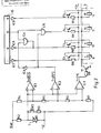
- Fig. 2 eine erfindungsgemäße Schaltungsanordnung der elektronischen Einrichtung zur Durchführung des erfindungsgemäßen Verfahrens.
- Fig. 1, the drive device of a motor vehicle and
- Fig. 2 shows an inventive circuit arrangement of the electronic device for performing the method according to the invention.
Das erfindungsgemäße Verfahren wurde bei der Antriebseinrichtung eines städtischen Autobusses verwirklicht. Ein in Figur 1 dargestellter Sechszylindermotor 1 mit Dieselbetrieb ist mit einem Kühlradiator 3 und mit Kühlwasserrohren 4 und 5 verbunden. Dies ist das Kühlwassersystem des Motors 1.The method according to the invention was implemented in the drive device of an urban bus. A six-
Der Motor 1 übergibt den Antrieb den nicht dargestellten Rädern über ein elektrohydraulisch gesteuertes hydromechanisches automatisches Wechselgetriebe 2 und über eine Kardanwelle 14. Ein das Stufenschalten des automatischen Wechselgetriebes 2 durchführendes elektohydraulisches Ventilsystem 6 wird von einer elektronischen Steuereinheit 13 gesteuert, die der Fahrzeugfahrer mit Hilfe eines Gangwählschalters 8 (Kontroller) beeinflussen kann.The
Die Elemente der in Figur 2 dargestellten elektronischen Einrichtung sind in der Steuereinheit 13 eingebaut, können aber auch als selbständige Einheit zusammengebaut werden.The elements of the electronic device shown in Figure 2 are installed in the
Zwecks Messung der Kühlwassertemperatur ist im Kühlwasserrohr 4, das der Rückflußzweig des Kühlwassersystems des Motors 1 ist, ein Temperatursignalgeber 7 eingebaut. Der Temperatursignalgeber 7 ist in diesem Fall ein Wärmegradmesserwiderstand R1 (NTK), der hinter dem Spannungsteiler R2 mit den Widerständen R4, R5, R6, R7 und mit den Komparatoren IC1, IC2, IC3 (µ A741) in Verbindung steht.For the purpose of measuring the cooling water temperature, a temperature signal transmitter 7 is installed in the cooling water pipe 4, which is the return branch of the cooling water system of the
Die Elektromagnete 9, 10, 11 und 12 der die I., II., III. und die R-(Rückwärts-) Gangstufe schaltenden Ventile des elektrohydraulischen Ventilsystems 6 sind einerseits über einen Schaltertransistor T1 (2 N 3055) an Masse, andererseits über Leistungsverstärker T2, T3, T4 und T5 (BD 240) an der Speisespannung angeschlossen.The
Der Schaltertransistor T1 ist über einen Widerstand R8 mit dem Ausgang des Komparators IC 3 verbunden.The switch transistor T1 is connected to the output of the
Der Stufenwählerteil 15 der Steuereinheit 13 ist in nicht dargestellter Weise mit dem Gangwählschalter 8 und mit den zur Bestimmung der jeweils adäquaten Gangstufe erforderlichen Signalgebern verbunden.The
Der der I. Gangstufe entsprechende Signalausgang des Stufenwählerteils 15 ist über eine Treiberstufe IC7 (7406) am Leistungsverstärker T2 und dazu parallel über einen Widerstand R9 an der Speisespannung angeschlossen.The signal output of the
In ähnlicher Weise ist der der R- (Rückwärts-) Gangstufe entsprechende Signalausgang des Stufenwählerteils 15 über eine Treiberstufe IC9 (7406) an den Leistungsverstärker T5 und dazu parallel über eine Widerstand R17 an der Speisespannung angeschlossen.Similarly, the signal output of the
Auch der der II. Gangstufe entsprechende Signalausgang des Stufenwählerteils 15 ist über eine Treiberstufe IC8 (7406) am entsprechenden Leistungsverstärker T3, und über einen Widerstand R10 an der Speisespannung angeschlossen, aber zu der Treiberstufe IC8 parallel ist auch der Ausgang des NAND-Tors (7437) einer Leistungsstufe IC4 am Leistungsverstärker T3 angeschlossen. Einer der Eingänge des NAND-Tors der Leistungsstufe IC4 ist über eine Treiberstufe IC6 (7406) am Ausgang des Komparators IC2, der andere Eingang ist am der III. Gangstufe entsprechenden Signalausgang des Stufenwählerteils 15 angeschlossen.The signal output of the
Der der IV. Gangstufe entsprechende Signalausgang des Stufenwählerteils 15 ist über den einen Eingang und Ausgang des NAND-Tors (7437) der Leistungsstufe IC5 am Leistungsverstärker T4 und dazu parallel über den Widerstand R11 an der Speisespannung angeschlossen. Der andere Eingang des NAND-Tors der Leistungs stufe IC5 ist ebenfalls am Ausgang des Komparators IC2 angeschlossen.The signal output of the
Die Pole des Wärmegradmesserwiderstandes R1 können mittels eines Handschalters K1 und eines Widerstandes R3 kurzgeschlossen werden.The poles of the heat resistance resistor R1 can be short-circuited by means of a manual switch K1 and a resistor R3.
Von dem oben beschriebenen System wird das erfindungsgemäße Verfahren wie folgt durchgeführt.From the system described above, the method according to the invention is carried out as follows.
Nach dem Anlassen des Motors 1 sendet der Temperatursignalgeber 7 der Steuereinheit 13 fortlaufend Signale über die Änderung der Kühlwassertemperatur. Die Komparatoren IC2 und IC3 werten dieses Signal aus, und zwar derart, daß wenn die Kühlwassertemperatur den Wert von 5°C erreicht, das Signal am Ausgang des Komparators IC3 erscheint und wenn sie den Wert von 25°C erreicht, das Signal am Ausgang des Komparators IC2 erscheint.After the
Die Temperaturwerte sollen derart gewählt werden, wie sie von der Belastbarkeit des Motors her zugelassen sind. die oben angegebenen Werte von 5°C bzw. 25 °C sind bei einem gegebenen Motor erfahrene Werte; sie können aber im allgemeinen bei jedem Motor verwendet werden.The temperature values should be selected in such a way that they are approved for the load capacity of the motor. the values of 5 ° C and 25 ° C given above are experienced values for a given engine; however, they can generally be used with any engine.
Wenn der Fahrzeugfahrer - normale Verkehrs- und Straßenverhältnisse angenommen - mit dem Kraftfahrzeug starten will, schaltet er mit dem Gangwählschalter 8 in die Direktstellung D. Wenn er danach mit dem Niederdrücken des Gaspedals das Kraftfahrzeug beschleunigt, würde die Steuereinheit 13 - zur Beschleunigung des Kraftfahrzeuges - dem elektrohydraulischen Ventilsystem 6 den Befehl zum fortlaufenden Aufwärtsschalten des automatischen Wechselgetriebes 2 bis zur III. Stufe geben.If the vehicle driver - assuming normal traffic and road conditions - wants to start with the motor vehicle, he switches to direct position D with the gear selector switch 8. If he then accelerates the motor vehicle by depressing the accelerator pedal, the
Solange aber die Kühlwassertemperatur den Wert von 5 °C nicht erreicht hat, erscheint kein Signal am Ausgang des Komparators IC3; so schließt der Schaltertransistor T1 die Elektromagneten 9, 10, 11, 12 nicht an Masse an. Auf diese Weise kommt vom Stufenwählteil 15 vergeblich ein Signal zum Einschalten der I. Gangstufe; der Elektromagnet 9 kann den Befehl nicht ausführen.As long as the cooling water temperature has not reached 5 ° C, no signal appears at the output of the comparator IC3; the switch transistor T1 does not connect the
Wenn die Kühlwassertemperatur den Wert von 5 °C erreicht hat, schließt der Schaltertransistor T1 die Elektromagneten 9, 10, 11, 12 aufgrund des Signals des Komparators IC3 an Masse an. Jetzt legt der Leistungsverstärker T2 den Elektromagneten 9 zum Erzeugen des der I. Gangstufe entsprechenden Signals des Stufenwählteils 15 an die Speisespannung und dann nach entsprechender Beschleunigung des Kraftfahrzeuges legt der Leistungs`verstärker T3 den Elektromagneten 10 zum Erzeugen des der II. Gangstufe entsprechenden Signals an die Speisespannung. In dieser Weise hat das elektrohydraulische Ventilsystem 6 das automatische Wechselgetriebe 2 in die I. und die II. Gangstufe geschaltet.When the cooling water temperature has reached 5 ° C, the switch transistor T1 connects the
Wenn das Kraftfahrzeug weiter beschleunigt wird, erreicht es die zum Schalten der III. Gangstufe erforderliche Geschwindigkeit. Der Stufenwählteil 15 erzeugt an seinem entsprechenden Ausgang das Signal zum Schalten der III. Gangstufe. Dies induziert aber am Ausgang des NAND-Tors der Leistungsstufe IC5 nur dann ein Signal, wenn dazu auch eine weitere Bedingung erfüllt ist. Nämlich auch das Signal des Ausgangs des Komparators IC2 muß am Eingang des NAND-Tors der Leistungsstufe IC5 erscheinen. Wenn diese Bedingung erfüllt ist, schließt der Leistungsverstärker T4 auf das Signal des Ausgangs des NAND-Tors der Leistungsstufe IC5 den Elektromagneten 11 an die Speisespannung an. In dieser Weise schaltet das elektrohydraulische Ventilsystem 6 das automatische Wechselgetriebe 2 in die III. Stufe.If the motor vehicle is accelerated further, it reaches the gear for shifting III. Gear required speed. The
Wenn die Kühlwassertemperatur den Wert von 25 °C noch nicht erreicht hat, erlischt das Signal am Ausgang des NAND-Tors der Leistungsstufe IC4 auf Wirkung des Signals des Komparators IC2 und erscheint am Ausgang des NAND-Tors der Leistungsstufe IC5 und das Schalten der III. Gangstufe erfolgt in der oben beschriebenen Weise.If the cooling water temperature has not yet reached 25 ° C, the signal at the output of the NAND gate of power level IC4 goes out due to the signal from comparator IC2 and appears at the output of the NAND gate of power level IC5 and the switching of III. Gear step takes place in the manner described above.
Wenn der Fahrzeugfahrer in den Rückwärtsgang schalten will, gibt er der Steuereinheit 13 mittels des Gangwählschalters 8 einen entsprechenden Befehl. Das der Rückwärtsgangstufe entsprechende Signal aus Stufenwählteils 15 schließt den Elektromagneten 12 des die Rückwärtsgangstufe verwirklichenden Ventils des elektrohydraulischen Ventilsystems 6 über die Antriebsstufe IC9 mittels des Leistungsverstärkers T5 an die Speisespannung an, und wenn die Kühlwassertemperatur höher als 5 °C ist, schließt der Schaltertransistor T1 den Elektromagneten 12 auf das Signal des Komparators IC3 auch an Masse an.If the vehicle driver wants to shift into reverse gear, he gives the control unit 13 a corresponding command by means of the gear selector switch 8. The signal corresponding to the reverse gear stage from
Aus den obigen Ausführungen ist ersichtlich, daß mit dem erfindungsgemäßen Verfahren das Schalten beliebiger Stufen von der Kühlwassertemperatur abhängig verboten werden kann.From the above statements it can be seen that the switching of any stages depending on the cooling water temperature can be prohibited with the inventive method.
Da manchmal derartige Gefahrensituationen vorkommen können, in denen nicht das Schonen des Motors, sondern das schnelle Anfahren wichtig ist, kann das Sytem mit Hilfe des Handschalters K1 von der Kühlwassertemperatur unabhängig gemacht werden.Since sometimes dangerous situations can occur in which it is not important to protect the engine but to start up quickly, the system can be made independent of the cooling water temperature using the manual switch K1.
Im System ist auch der bereits erwähnte Komparator IC1 (µ A741) eingebaut, dies hat aber mit dem erfindungsgemäßen Verfahren nichts zu tun. Die gegebene Ausbildung bietet aber von sich selbt heraus an, daß auch die Überhitzung des Kühlwassers beobachtet werden kann. Deshalb erzeugt der Komparator IC1 beim Erreichen des Wertes von 85 °C ein Signal, mit dem eine nicht dargestellte Warnsignaleinrichtung (Signallampe, akustisches Signal) bestätigt werden kann.The comparator IC1 (μ A741) already mentioned is also installed in the system, but this has nothing to do with the method according to the invention. The given training offers itself that the overheating of the cooling water can also be observed. Therefore, when the value of 85 ° C. is reached, the comparator IC1 generates a signal with which a warning signal device (signal lamp, acoustic signal), not shown, can be confirmed.
Claims (1)
Applications Claiming Priority (1)
| Application Number | Priority Date | Filing Date | Title |
|---|---|---|---|
| HU862730A HU196927B (en) | 1986-07-01 | 1986-07-01 | Method for stage coupling the automatic gear box of motor vehicle depending on the temperature of cooling water |
Publications (1)
| Publication Number | Publication Date |
|---|---|
| EP0324877A1 true EP0324877A1 (en) | 1989-07-26 |
Family
ID=10960874
Family Applications (1)
| Application Number | Title | Priority Date | Filing Date |
|---|---|---|---|
| EP88100808A Withdrawn EP0324877A1 (en) | 1986-07-01 | 1988-01-20 | Procedure enabling the change of gears in an automatic transmission of a motor vehicle, dependant on the cooling water temperature |
Country Status (3)
| Country | Link |
|---|---|
| US (1) | US4894780A (en) |
| EP (1) | EP0324877A1 (en) |
| HU (1) | HU196927B (en) |
Cited By (2)
| Publication number | Priority date | Publication date | Assignee | Title |
|---|---|---|---|---|
| EP0530876A2 (en) * | 1991-09-06 | 1993-03-10 | General Motors Corporation | Control apparatus for an automatic transmission |
| EP3909823A1 (en) * | 2020-05-12 | 2021-11-17 | RENAULT s.a.s. | Method for controlling the starting of a motor vehicle equipped with an automatic gearbox and a system for after-treatment of the exhaust gases |
Families Citing this family (17)
| Publication number | Priority date | Publication date | Assignee | Title |
|---|---|---|---|---|
| JPH0297761A (en) * | 1988-09-30 | 1990-04-10 | Aisin Seiki Co Ltd | Electronically controlled automatic transmission |
| JP2948230B2 (en) * | 1989-02-21 | 1999-09-13 | マツダ株式会社 | Engine control device for vehicle with automatic transmission |
| DE3928814A1 (en) * | 1989-08-31 | 1991-03-14 | Porsche Ag | MOTOR VEHICLE WITH AN AUTOMATIC GEARBOX |
| US4986145A (en) * | 1989-11-16 | 1991-01-22 | Chrysler Corporation | Method of engine model determination for use in an electronically-controlled automatic transmission |
| JP2897358B2 (en) * | 1990-07-11 | 1999-05-31 | 日産自動車株式会社 | Hydraulic pressure control device for automatic transmission |
| US5050451A (en) * | 1990-10-01 | 1991-09-24 | Eaton Corporation | Transmission lubricant temperature/viscosity determination method/apparatus |
| US5275069A (en) * | 1991-03-31 | 1994-01-04 | Mazda Motor Corporation | Control system for automatic transmission |
| US5305663A (en) * | 1992-08-10 | 1994-04-26 | Ford Motor Company | Automatic transmission control system |
| US5803863A (en) * | 1997-03-03 | 1998-09-08 | Caterpillar Inc. | Transmission warm-up control strategy |
| DE19849058A1 (en) * | 1998-10-24 | 2000-04-27 | Zahnradfabrik Friedrichshafen | Method for controlling high temperature mode of operation of electronically controlled automatic gears selects temperature reducing gear changing programme if temperature is high |
| US6227153B1 (en) | 1999-09-17 | 2001-05-08 | General Electric Company | Engine cooling apparatus and method |
| US6394044B1 (en) | 2000-01-31 | 2002-05-28 | General Electric Company | Locomotive engine temperature control |
| US6283100B1 (en) | 2000-04-20 | 2001-09-04 | General Electric Company | Method and system for controlling a compression ignition engine during partial load conditions to reduce exhaust emissions |
| US6286311B1 (en) | 2000-05-16 | 2001-09-11 | General Electric Company | System and method for controlling a locomotive engine during high load conditions at low ambient temperature |
| US6230668B1 (en) | 2000-05-22 | 2001-05-15 | General Electric Company | Locomotive cooling system |
| DE10354930B3 (en) * | 2003-11-25 | 2005-08-04 | Adam Opel Ag | Starting up process for vehicle in unfavorable weather involves using weather values to decide if gear should be engaged with clutch closed or open |
| US7410446B2 (en) * | 2005-12-19 | 2008-08-12 | Caterpillar Inc. | Oil warming strategy for transmission |
Citations (3)
| Publication number | Priority date | Publication date | Assignee | Title |
|---|---|---|---|---|
| DE3325002A1 (en) * | 1982-07-12 | 1984-01-12 | Honda Giken Kogyo K.K., Tokyo | CONTROL METHOD FOR A DEVICE FOR PREVENTING THE CRAWLING OF A VEHICLE EQUIPPED WITH AN AUTOMATIC TRANSMISSION |
| US4531432A (en) * | 1982-08-21 | 1985-07-30 | Toyota Jidosha Kabushiki Kaisha | Automatic transmission control device for automobile |
| US4572029A (en) * | 1981-08-26 | 1986-02-25 | Toyota Jidosha Kogyo Kabushiki Kaisha | Speed change control method and device of automatic transmission for vehicle |
Family Cites Families (4)
| Publication number | Priority date | Publication date | Assignee | Title |
|---|---|---|---|---|
| JPS487137B1 (en) * | 1968-10-30 | 1973-03-03 | ||
| JPS534589B2 (en) * | 1972-06-26 | 1978-02-18 | ||
| EP0037050A3 (en) * | 1980-03-27 | 1984-05-09 | Nissan Motor Co., Ltd. | Lock-up control system for lock-up type automatic transmission |
| JPS6049793B2 (en) * | 1981-03-30 | 1985-11-05 | 日産自動車株式会社 | Lock-up control device for lock-up automatic transmission |
-
1986
- 1986-07-01 HU HU862730A patent/HU196927B/en not_active IP Right Cessation
-
1988
- 1988-01-20 EP EP88100808A patent/EP0324877A1/en not_active Withdrawn
- 1988-01-21 US US07/146,516 patent/US4894780A/en not_active Expired - Fee Related
Patent Citations (3)
| Publication number | Priority date | Publication date | Assignee | Title |
|---|---|---|---|---|
| US4572029A (en) * | 1981-08-26 | 1986-02-25 | Toyota Jidosha Kogyo Kabushiki Kaisha | Speed change control method and device of automatic transmission for vehicle |
| DE3325002A1 (en) * | 1982-07-12 | 1984-01-12 | Honda Giken Kogyo K.K., Tokyo | CONTROL METHOD FOR A DEVICE FOR PREVENTING THE CRAWLING OF A VEHICLE EQUIPPED WITH AN AUTOMATIC TRANSMISSION |
| US4531432A (en) * | 1982-08-21 | 1985-07-30 | Toyota Jidosha Kabushiki Kaisha | Automatic transmission control device for automobile |
Cited By (4)
| Publication number | Priority date | Publication date | Assignee | Title |
|---|---|---|---|---|
| EP0530876A2 (en) * | 1991-09-06 | 1993-03-10 | General Motors Corporation | Control apparatus for an automatic transmission |
| EP0530876A3 (en) * | 1991-09-06 | 1994-03-09 | Gen Motors Corp | |
| EP3909823A1 (en) * | 2020-05-12 | 2021-11-17 | RENAULT s.a.s. | Method for controlling the starting of a motor vehicle equipped with an automatic gearbox and a system for after-treatment of the exhaust gases |
| FR3110128A1 (en) * | 2020-05-12 | 2021-11-19 | Renault Sas | PROCEDURE FOR CONTROLLING THE STARTING OF A MOTOR VEHICLE EQUIPPED WITH AN AUTOMATIC GEARBOX AND AN EXHAUST GAS AFTER-TREATMENT SYSTEM |
Also Published As
| Publication number | Publication date |
|---|---|
| US4894780A (en) | 1990-01-16 |
| HUT45940A (en) | 1988-09-28 |
| HU196927B (en) | 1989-02-28 |
Similar Documents
| Publication | Publication Date | Title |
|---|---|---|
| EP0324877A1 (en) | Procedure enabling the change of gears in an automatic transmission of a motor vehicle, dependant on the cooling water temperature | |
| DE69929845T2 (en) | Independent control of continuous brakes on the transmission side and the engine side during gear shifting | |
| WO1995009741A1 (en) | Method of controlling the output torque of an automatic transmission | |
| DE102004022929B4 (en) | Fault detection device for a hydraulic pressure control circuit of a vehicle | |
| DE60212384T2 (en) | METHOD FOR CHANGING THE DRIVE DIRECTION | |
| WO1995033631A1 (en) | Retarder control | |
| DE102011008363A1 (en) | Starting clutch protection on a slope at vehicle start | |
| DE102011076034A1 (en) | Vehicle and method for operating a vehicle | |
| DE3016620A1 (en) | DRIVE UNIT | |
| DE60008957T2 (en) | Control system for the lockup clutch of a torque converter | |
| DE102013003520A1 (en) | Control method for a dual-clutch transmission | |
| DE19643086B4 (en) | Retarder braking torque adaptation when coupling and shifting | |
| DE102006036755A1 (en) | A method of operating a vehicle powertrain during an activated engine start-stop function | |
| EP0291088A2 (en) | Process for the stepwise changing of the gears of an electrohydraulically controlled automatic transmission in an automotive vehicle | |
| DE102005021924A1 (en) | Control method for automatic transmission of motor vehicle involves disengaging static function of automatic transmission when vehicle speed and turbine characteristic parameter of e.g. torque converter is lower than predetermined value | |
| DE4392959B4 (en) | Method and device for accelerating the heating of the vehicle engine in a vehicle equipped with a retarder | |
| DE102007034301A1 (en) | Torque converter impact control system for internal combustion engine of vehicle, has end amplification module selectively setting end amplification by amplification and/or increased amplification and/or mixed amplification | |
| DE4446085B4 (en) | Method and arrangement for retarder-controlled influencing of the switching points in switching systems for transmissions of motor vehicles | |
| DE10153413A1 (en) | Kick down control method for five speed automatic motor vehicle gearbox uses double phase gear change with secondary phase if kick down control signal is received | |
| DE3632960A1 (en) | Control device for a drive assembly, comprising an engine and an automatic transmission, used to drive a motor vehicle | |
| DE102015223595A1 (en) | Method for coupling a power take-off | |
| DE102012001078B4 (en) | PROCEDURE AND HYDRAULIC CONTROL SYSTEM FOR DETECTING THE PRESENCE OF HYDRAULIC PRESSURE IN A GEARBOX | |
| DE102008024059A1 (en) | Automatic switch-on process controlling method for automatically switch-off drive unit of motor vehicle, involves starting automatic switch-on process and closing clutch in non-direct, continuous and complete manner | |
| DE102008008930A1 (en) | motor vehicle | |
| DE3822316C2 (en) |
Legal Events
| Date | Code | Title | Description |
|---|---|---|---|
| PUAI | Public reference made under article 153(3) epc to a published international application that has entered the european phase |
Free format text: ORIGINAL CODE: 0009012 |
|
| AK | Designated contracting states |
Kind code of ref document: A1 Designated state(s): AT DE FR GB |
|
| GBC | Gb: translation of claims filed (gb section 78(7)/1977) | ||
| EL | Fr: translation of claims filed | ||
| 17P | Request for examination filed |
Effective date: 19891215 |
|
| 17Q | First examination report despatched |
Effective date: 19910517 |
|
| STAA | Information on the status of an ep patent application or granted ep patent |
Free format text: STATUS: THE APPLICATION IS DEEMED TO BE WITHDRAWN |
|
| 18D | Application deemed to be withdrawn |
Effective date: 19911128 |