EP0324639A2 - Wafer grain gas generator - Google Patents
Wafer grain gas generator Download PDFInfo
- Publication number
- EP0324639A2 EP0324639A2 EP89300307A EP89300307A EP0324639A2 EP 0324639 A2 EP0324639 A2 EP 0324639A2 EP 89300307 A EP89300307 A EP 89300307A EP 89300307 A EP89300307 A EP 89300307A EP 0324639 A2 EP0324639 A2 EP 0324639A2
- Authority
- EP
- European Patent Office
- Prior art keywords
- wafers
- combustion chamber
- cushion members
- gas generator
- gas
- Prior art date
- Legal status (The legal status is an assumption and is not a legal conclusion. Google has not performed a legal analysis and makes no representation as to the accuracy of the status listed.)
- Granted
Links
Images
Classifications
-
- B—PERFORMING OPERATIONS; TRANSPORTING
- B60—VEHICLES IN GENERAL
- B60R—VEHICLES, VEHICLE FITTINGS, OR VEHICLE PARTS, NOT OTHERWISE PROVIDED FOR
- B60R21/00—Arrangements or fittings on vehicles for protecting or preventing injuries to occupants or pedestrians in case of accidents or other traffic risks
- B60R21/02—Occupant safety arrangements or fittings, e.g. crash pads
- B60R21/16—Inflatable occupant restraints or confinements designed to inflate upon impact or impending impact, e.g. air bags
- B60R21/26—Inflatable occupant restraints or confinements designed to inflate upon impact or impending impact, e.g. air bags characterised by the inflation fluid source or means to control inflation fluid flow
- B60R21/264—Inflatable occupant restraints or confinements designed to inflate upon impact or impending impact, e.g. air bags characterised by the inflation fluid source or means to control inflation fluid flow using instantaneous generation of gas, e.g. pyrotechnic
- B60R21/2644—Inflatable occupant restraints or confinements designed to inflate upon impact or impending impact, e.g. air bags characterised by the inflation fluid source or means to control inflation fluid flow using instantaneous generation of gas, e.g. pyrotechnic using only solid reacting substances, e.g. pellets, powder
-
- B—PERFORMING OPERATIONS; TRANSPORTING
- B01—PHYSICAL OR CHEMICAL PROCESSES OR APPARATUS IN GENERAL
- B01J—CHEMICAL OR PHYSICAL PROCESSES, e.g. CATALYSIS OR COLLOID CHEMISTRY; THEIR RELEVANT APPARATUS
- B01J7/00—Apparatus for generating gases
-
- B—PERFORMING OPERATIONS; TRANSPORTING
- B60—VEHICLES IN GENERAL
- B60R—VEHICLES, VEHICLE FITTINGS, OR VEHICLE PARTS, NOT OTHERWISE PROVIDED FOR
- B60R21/00—Arrangements or fittings on vehicles for protecting or preventing injuries to occupants or pedestrians in case of accidents or other traffic risks
- B60R21/02—Occupant safety arrangements or fittings, e.g. crash pads
- B60R21/16—Inflatable occupant restraints or confinements designed to inflate upon impact or impending impact, e.g. air bags
-
- Y—GENERAL TAGGING OF NEW TECHNOLOGICAL DEVELOPMENTS; GENERAL TAGGING OF CROSS-SECTIONAL TECHNOLOGIES SPANNING OVER SEVERAL SECTIONS OF THE IPC; TECHNICAL SUBJECTS COVERED BY FORMER USPC CROSS-REFERENCE ART COLLECTIONS [XRACs] AND DIGESTS
- Y10—TECHNICAL SUBJECTS COVERED BY FORMER USPC
- Y10T—TECHNICAL SUBJECTS COVERED BY FORMER US CLASSIFICATION
- Y10T29/00—Metal working
- Y10T29/49—Method of mechanical manufacture
- Y10T29/49428—Gas and water specific plumbing component making
-
- Y—GENERAL TAGGING OF NEW TECHNOLOGICAL DEVELOPMENTS; GENERAL TAGGING OF CROSS-SECTIONAL TECHNOLOGIES SPANNING OVER SEVERAL SECTIONS OF THE IPC; TECHNICAL SUBJECTS COVERED BY FORMER USPC CROSS-REFERENCE ART COLLECTIONS [XRACs] AND DIGESTS
- Y10—TECHNICAL SUBJECTS COVERED BY FORMER USPC
- Y10T—TECHNICAL SUBJECTS COVERED BY FORMER US CLASSIFICATION
- Y10T29/00—Metal working
- Y10T29/49—Method of mechanical manufacture
- Y10T29/49826—Assembling or joining
- Y10T29/49863—Assembling or joining with prestressing of part
Definitions
- the present invention relates to gas generators. More particularly, the present invention relates to gas generators that utilize the combustion of a solid fuel gas generant composition for the generation of a gas for such purposes as rapidly inflating vehicle passive restraint inflatable crash protection bags, i.e., gas bags.
- Inflators such as shown in U.S. Patent 4,547,342 to Adams et al and U.S. Patent 4,005,876 to Jorgensen et al , both of which are assigned to the assignee of the present invention, contain gas generant in the form of pressed tablets (similar in shape to aspirin tablets), illustrated at 62 in Adams et al and at 10 in Jorgensen et al , which are randomly packed into the inflator combustion chamber. While the use of such pressed tablets is satisfactory for most purposes, the tablets provide an high initial surface area for burning and thus do not provide as soft of inflation onset as may be desired.
- Burn surface neutrality relates to the change in surface area being burned at different times during the combustion process. As the burn surface neutrality is increased for a particular gas generant configuration, the surface area being burned at any point in the combustion process is more uniform. An improved burn surface neutrality has the effect of reducing the initial pressure peak to thus provide a softer onset. An improved or increased burn surface neutrality with less surface area reduction at tailoff is also desired to allow a more uniform inflator gas flow history and better utilization of the gas generant.
- the volumetric loading fraction obtainable with randomly packed pressed pellets is typically in the range of 55 to 57 percent. This is due to the volume lost in the interstitial spaces between the pellets. Because of volume restrictions for packaging air bag systems in a vehicle and the constant demands for reduced size and weight, it is considered desirable to increase this volumetric loading fraction for increased loading density so that the size of the combustion chamber may be made smaller relative to the amount of gas generant material.
- driver side inflators It has been proposed for driver side inflators to form the pyrotechnic combustible material for inflators in the form of separate discs having a separator means disposed between adjacent discs to facilitate quick uniform combustion of the material.
- U.S. Patents 3,901,530 to Radke and 4,131,300 to Radke et al It has also been proposed with regard to passenger side inflaters to press the propellant into wafers and to configure each wafer in a manner to allow space for a propellant powder to be uniformly placed between the wafers to cushion each wafer from shock and vibration and for the purpose of insuring near instantaneous ignition of all wafers.
- U.S. Patent 4,158,696 to Wilhelm It has been proposed for driver side inflators to form the pyrotechnic combustible material for inflators in the form of separate discs having a separator means disposed between adjacent discs to facilitate quick uniform combustion of the material.
- stacked wafers While the proposed use of stacked wafers would permit higher volumetric loading, it is also considered desirable that they be stacked in such a configuration that good filtering of solid particulates can be obtained to provide a decreased plugging of filters and clean inflation gas while also allowing improved burn surface neutrality for smoother performance as previously discussed.
- the disposition of propellant powder between the wafers may furthermore undesirably result in a fast onset of burning for a higher initial pressure peak and a decreased burn surface neutrality.
- the solid gas generant is typically hard and brittle when pressed into wafers or pellets and may be fractured or damaged if allowed to move or rattle around in the inflator combustion chamber. To insure satisfactory survival after many years in an automobile environment, it is also desirable that the gas generant be packaged in a manner which does not allow movement, breakage, or attrition by wearing against another gas generant wafer or a hard inflator surface.
- a gas generator or inflator which may be used to inflate vehicle passive restraint inflatable crash protective bags on the passenger sides of vehicles.
- the inflator includes an elongated cylindrical member 12 and an end cap 14 integral therewith which closes one end thereof.
- the end cap 14 includes a threaded pin or fitting 16 integral therewith which may be used to attach the inflator 10 to a mounting bracket (not shown).
- the members 12, 14, and 16 are composed preferably of aluminum which is light weight, they may be composed of any other suitable material.
- a generally cylindrical metallic member 18 which functions as an igniter tube.
- a plug member 20 of a suitable material such as compressible foamed material closes one end of the igniter tube 18, and the plugged end is positioned within a cavity 22 of a plate-like member 24 which engages the end cap 14 over the diameter thereof and which may be called an igniter tube locater, the cavity size being substantially the same as the outer diameter of the plugged end portion of the igniter tube 18.
- an end cap 28 Welded to the housing 12 by weld 26 or attached by other suitable means is an end cap 28.
- the end cap 28 has a cavity 30 centrally thereof and generally in alignment with the igniter tube 18.
- the open end portion 32 of the igniter tube 18 is flared outwardly.
- a metallic housing member 34 of an initiator assembly, generally illustrated at 36, is screwed into or otherwise suitably attached within the end cap cavity 30 and includes a cylindrical extension portion 38 which is slip fitted or otherwise suitably attached within the flared end portion 32 of the igniter tube 18.
- Cavity 30 is enlarged near its outlet to provide a shoulder 40 to engage an outer enlarged portion 41 of the initiator housing 34.
- a squib 42 Contained within the extension portion 38 is a squib 42 or other suitable initiator commonly known to those of ordinary skill in the art to which this invention pertains.
- the squib 42 is connected to electrical lead wires 44 which extend outwardly through an aperture 46 in the initiator housing 34.
- Contained within the igniter tube 18 adjacent the flared end portion 32 is a suitable plug 48. Extending through the plug 48 and over the length of the igniter tube 18 and into plug 20 is a suitable fuse 50 which is ignitable by the squib 421.
- Contained within the igniter tube 18 between the plugs 20 and 48 is a suitable pyrotechnic material illustrated at 52 which may be any of a variety of compositions meeting the requirements for rapid ignition and non-toxicity.
- a typical material for this use may be a granular mixture of 25 percent by weight of boron and 75 percent of potassium nitrate.
- This pyrotechnic material 52 is ignitable by the fuse 50.
- the plugs 20 and 48 may be made out of any suitable material such as, for example, compressible foam and function to suitably retain the pyrotechnic material 52 within the igniter tube 18.
- the igniter tube 18 includes a plurality of perforations one of which is illustrated at 54 for routing of ignition gases from combustion of the pyrotechnic material 52 into the elongate combustion chamber illustrated at 56.
- a thin layer of aluminum foil 58 or other suitable rupturable material surrounds the perforated igniter tube 18 to maintain the integrity of the pyrotechnic material 52 inside of the igniter tube 18 until ignition at which time the pressure of ignition will rupture the foil 58 to allow ignition gases into the combustion chamber 56 to ignite combustible gas generating material which is contained therein and which will be discussed in greater detail hereinafter.
- the combustion chamber 56 is enclosed over the length thereof by a perforated metal basket 60, composed of steel or other suitable material. Gases are led from the combustion chamber 56 through perforations 61 in the perforated basket 60 into a space between the perforated basket 60 and the wall of the housing 12 which contains a gas filtering assembly generally illustrated at 62. Adjacent the perforated basket 60 and surrounding the perforated basket 60 is a filter pack 64 which includes alternate layers of screen and ceramic filter paper. Surrounding the filter pack 64 is a screen pack 66 which includes 11 ⁇ 2 layers of coarse screen, i.e., 8 mesh screen. However, in accordance with the present invention, the filtering assembly 62 may contain any other suitable arrangement of filtering components other than that described.
- a plurality of apertures 68 for release of generated gas from the combustion chamber 56 into a gas bag (not shown) which is suitably attached thereto.
- Covering the inside wall of the housing 12 to provide an hermatic seal for the inflator is a layer of aluminum foil 70 or other suitable material which is rupturable by the gases generated in the combustion chamber 56.
- the apertures 68 may be positioned over a little less than one-half of the surface circumferentially of the inflator housing 12.
- the 11 ⁇ 2 layers of screen for the screen pack 66 are wrapped to provide a double layer of screen in front of the apertures 68.
- the ratio of the maximum or initial surface area to the average surface area may typically be 1.79 which is indicative of a high initial gas bag fill rate which then tapers off.
- Such randomly packed pellets may also typically have a ratio of final surface area to initial surface area of about 0.18 which also includes a low burn surface neutrality.
- Burn surface neutrality refers to the degree to which the surface area of the gas generant is uniform throughout the combustion process. As the ratio of surface areas at two different times during this process approaches a ratio of one, it may be said that the burn surface neutrality is increased. High burn surface neutrality is desired to provide a softer onset of inflation, a more uniform gas bag fill rate, and better utilization of the gas generant material.
- volumetric loading fraction obtainable with randomly packed pressed pellets is typically in the range of 55 to 57 percent because of the volume lost in the interstitial spaces between the pellets.
- Volumetric loading density refers to the ratio of the volume of gas generant material in an inflator combustion chamber to the volume of the combustion chamber. It is desirable to increase the loading density and thus reduce the combustion chamber size for a given volume of gas generant for reduced size and weight of the inflator.
- a grain generally illustrated at 72 which is composed of a plurality of wafers 74 of combustible gas generating material which are arranged in a side by side array and spaced apart from each other.
- the gas generating material may be one of any number of compositions meeting the requirements of burning rate, non-toxicity, and flame temperature.
- One composition which may be utilized is that described in U.S. Patent 4,203,787 to Schneiter et al .
- Another composition that may advantageously be utilized is that described in U.S. Patent 4,369,079 to Shaw .
- the wafers 74 have the shape of washers whose inner and outer diameters are generally the same as the inner and outer diameters respectively of the combustion chamber 56, i.e., as shown in Figure 2, they have substantially the same shape as the cross-sectional shape of the combustion chamber.
- the igniter tube 18 passes through the central core of the wafers 74.
- Wafers 74 may typically have a thickness of 0.20 inches, an outer diameter, illustrated at 76 in Figure 2, typically of 1.3 to 2.0 inches which is substantially equal to (but slightly smaller than) the combustion chamber diameter 77, and have a central hole diameter, illustrated at 82 in Figure 2, typically of 0.25 to 0.50 inches which is substantially equal to (but slightly larger than) the outer diameter 84 of the igniter tube 18 whereby the wafers 74 extend from the igniter tube 18 radially outwardly to efficiently fill the combustion chamber 56.
- the volumetric loading fraction of the stacked wafer grain 72 is dependent upon the wafer thickness and the distance the wafers are spaced apart from each other.
- volumetric loading density would be approximately 73 percent.
- volumetric loading densities in the range from 65 to 80 percent are believed to be practical.
- the solid gas generant is hard and brittle when pressed into wafers and may be fractured or damaged if allowed to move or rattle around in the inflator combustion chamber. To insure satisfactory survival after many years in an automobile environment, the gas generant should be packaged in a manner which does not allow movement, breakage, or attrition by wearing against another gas generant wafer or a hard inflator surface. In addition, in order to reduce the plugging of filters and provide cleaner gas to the gas bag, it is desirable to retain an increased amount of solid residue in the combustion chamber 56.
- a plurality of meshed compressible cushion members 78 are disposed in alternating relation between the wafers 74 and compressed between the wafers 74.
- these cushion members 78 have a central core to allow installation of the igniter tube 18 and have outer and inner diameters approximately equal to the outer and inner diameters respectively of the wafers 74.
- the cushion members 78 are formed from a screen or other suitable meshed material in order that a gas flow path may be created which allows ignition of all the flat wafer surfaces from the meshed to provide an open path for the combustion products to flow from the gas generant surfaces toward the surrounding filtering assembly 62 on their way out of the inflator and into the gas bag.
- the cushion members 78 are preferably formed from wire screen, which preferably is in the range of about 20 to 50 mesh, in order that they may serve as a cool surface to condense and collect solid combustion products in the combustion chamber 56 so as to reduce clogging of the primary particulate and cooling filters in the filtering assembly 62 so that cleaner inflation gas may thereby be provided to a gas bag.
- the screens 86 from which the cushion members are made are preferably pressed into a wave form as illustrated in Figure 1 to provide a spring or cushion effect as well as increased transverse flow area for combustion gases.
- the thickness, illustrated at 88, of a formed screen cushion member 78 is preferably from about 1.5 to 5 times the thickness, illustrated at 90, of the unpressed screen.
- the array of alternating wafers 74 and cushion members 78 is compressed and held in the combustion chamber 56 by a disc retainer member 80 to structurally suspend each individual wafer 74 between compressed adjacent cushion members 78 to prevent movement breakage of the wafers or wearing of the wafers against other wafers or a hard inflator surface or any other damage to the wafers.
- an improved volumetric loading fraction in the range of 65 to 80 percent may be obtained.
- the volumetric loading density would be approximately 73 percent, as compared to a range of 55 to 57 percent which is typical of the randomly packed pressed tablets.
- the ratio of maximum or initial surface area to average surface area may be typically 1.27, which indicates a substantially improved burn surface neutrality over a typical ratio of 1.79 for randomly packed pressed pellets having outside diameter of 0.375 inches and thicknesses of 0.150 inches.
- the ratio of the final surface area to the initial surface area of such a stacked wafer grain may be typically 0.57, which also indicates an improved burn surface neutrality over the pellets at a typical ratio of 0.18.
- the stacked wafer grain 72 of the present invention is additionally provided so that an improved burn surface neutrality may be achieved for more uniform inflator gas flow and better utilization of the gas generant.
- the pellets which are shown at 10 in the Jorgensen et al patent, are replaced with a grain similar to the grain 72 to achieve the advantages previously discussed with respect to the embodiment of Figures 1 and 2 of this application.
- Functioning of the inflator 10 begins with an electrical signal from a crash sensor (not shown) through lead wires 44 to the initiator 42.
- the initiator 42 fires and initiates burning of the fuse 50 which in turn effects combustion of the pyrotechnic material 52.
- the gases from burning of the pyrotechnic material 52 burst through the perforations 54 in the igniter tube 18 and the aluminum foil 58 to ignite the plurality of wafers 74 in the combustion chamber 56.
- the burning of the wafers 74 releases inflator gases which flow through the meshed cushion members, which cool and remove some particulate residue therefrom, and then leave the combustion chamber 56 through the perforated basket 60.
- the inflator gases then flow through the filter pack 64 then the screen pack 66 which further cool and remove particulate residue therefrom.
- the inflator gases then burst through the aluminum foil 70 and exit the inflator through apertures 68 in the housing 12 and enter a gas bag (not shown).
- the stacked wafer grain 72 is provided to achieve improved burn surface neutrality for more uniform inflater gas flow and better utilization of the gas generant, retention of increased amounts of solid residue in the combustion chamber for improved filtration capability and cleaner inflation gas, a higher volumetric loading fraction so that reduced size and weight inflators may be provided, and the structural suspension of each individual wafer for reduced breakage or damage during the many years that the inflator may remain in an automobile.
Landscapes
- Engineering & Computer Science (AREA)
- Mechanical Engineering (AREA)
- Chemical & Material Sciences (AREA)
- Physics & Mathematics (AREA)
- Fluid Mechanics (AREA)
- Organic Chemistry (AREA)
- Chemical Kinetics & Catalysis (AREA)
- Air Bags (AREA)
- Feeding, Discharge, Calcimining, Fusing, And Gas-Generation Devices (AREA)
Abstract
Description
- The present invention relates to gas generators. More particularly, the present invention relates to gas generators that utilize the combustion of a solid fuel gas generant composition for the generation of a gas for such purposes as rapidly inflating vehicle passive restraint inflatable crash protection bags, i.e., gas bags.
- Inflators such as shown in U.S. Patent 4,547,342 to Adams et al and U.S. Patent 4,005,876 to Jorgensen et al, both of which are assigned to the assignee of the present invention, contain gas generant in the form of pressed tablets (similar in shape to aspirin tablets), illustrated at 62 in Adams et al and at 10 in Jorgensen et al, which are randomly packed into the inflator combustion chamber. While the use of such pressed tablets is satisfactory for most purposes, the tablets provide an high initial surface area for burning and thus do not provide as soft of inflation onset as may be desired.
- It is thus considered desirable to be able to tailor inflator performance to meet requirements for fast function time but with a relatively slow inflation onset. These requirements may be achieved by a gas generant configuration wherein the burn surface neutrality is improved or increased over that of the randomly packed compressed tablet configuration. Burn surface neutrality relates to the change in surface area being burned at different times during the combustion process. As the burn surface neutrality is increased for a particular gas generant configuration, the surface area being burned at any point in the combustion process is more uniform. An improved burn surface neutrality has the effect of reducing the initial pressure peak to thus provide a softer onset. An improved or increased burn surface neutrality with less surface area reduction at tailoff is also desired to allow a more uniform inflator gas flow history and better utilization of the gas generant.
- The volumetric loading fraction obtainable with randomly packed pressed pellets is typically in the range of 55 to 57 percent. This is due to the volume lost in the interstitial spaces between the pellets. Because of volume restrictions for packaging air bag systems in a vehicle and the constant demands for reduced size and weight, it is considered desirable to increase this volumetric loading fraction for increased loading density so that the size of the combustion chamber may be made smaller relative to the amount of gas generant material.
- It has been proposed for driver side inflators to form the pyrotechnic combustible material for inflators in the form of separate discs having a separator means disposed between adjacent discs to facilitate quick uniform combustion of the material. In this respect, see U.S. Patents 3,901,530 to Radke and 4,131,300 to Radke et al. It has also been proposed with regard to passenger side inflaters to press the propellant into wafers and to configure each wafer in a manner to allow space for a propellant powder to be uniformly placed between the wafers to cushion each wafer from shock and vibration and for the purpose of insuring near instantaneous ignition of all wafers. In this respect, see U.S. Patent 4,158,696 to Wilhelm.
- While the proposed use of stacked wafers would permit higher volumetric loading, it is also considered desirable that they be stacked in such a configuration that good filtering of solid particulates can be obtained to provide a decreased plugging of filters and clean inflation gas while also allowing improved burn surface neutrality for smoother performance as previously discussed. The disposition of propellant powder between the wafers may furthermore undesirably result in a fast onset of burning for a higher initial pressure peak and a decreased burn surface neutrality.
- The solid gas generant is typically hard and brittle when pressed into wafers or pellets and may be fractured or damaged if allowed to move or rattle around in the inflator combustion chamber. To insure satisfactory survival after many years in an automobile environment, it is also desirable that the gas generant be packaged in a manner which does not allow movement, breakage, or attrition by wearing against another gas generant wafer or a hard inflator surface.
- It is therefore an object of the present invention to provide a gas generant configuration which has good burn surface neutrality for smooth inflator performance.
- It is another object of the present invention to provide such a gas generant configuration wherein there is reduced plugging of filters and the inflation gas is clean.
- It is a further object of the present invention to provide such a gas generant configuration wherein the gas generant material is not easily fractured or damaged during the many years the inflator must remain in an automobile.
- It is still another object of the present invention to provide such a gas generant configuration which has a high volumetric loading fraction so that the combustion chamber size can be reduced.
- It is yet another object of the present invention to provide a gas generant configuration for an inflator which is rugged, reliable, and inexpensive.
- The above and other objects, features, and advantages of this invention will be apparent in the following detailed description of the preferred embodiments thereof which is to be read in connection with the accompanying drawings.
-
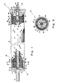
- Figure 1 is a side view, partly in section, of a gas generator which embodies the present invention; and
- Figure 2 is a sectional view of the gas generator of Figure 1 taken along the lines 2-2 thereof.
- Referring to the drawings, there is shown generally at 10 a gas generator or inflator which may be used to inflate vehicle passive restraint inflatable crash protective bags on the passenger sides of vehicles. The inflator includes an elongated
cylindrical member 12 and anend cap 14 integral therewith which closes one end thereof. Theend cap 14 includes a threaded pin or fitting 16 integral therewith which may be used to attach theinflator 10 to a mounting bracket (not shown). Although themembers - Extending generally over the length of the
cylindrical member housing 12 and centrally located so as to be generally concentric with thehousing 12 is a generally cylindricalmetallic member 18 which functions as an igniter tube. Aplug member 20 of a suitable material such as compressible foamed material closes one end of theigniter tube 18, and the plugged end is positioned within acavity 22 of a plate-like member 24 which engages theend cap 14 over the diameter thereof and which may be called an igniter tube locater, the cavity size being substantially the same as the outer diameter of the plugged end portion of theigniter tube 18. - Welded to the
housing 12 byweld 26 or attached by other suitable means is anend cap 28. Theend cap 28 has acavity 30 centrally thereof and generally in alignment with theigniter tube 18. Theopen end portion 32 of theigniter tube 18 is flared outwardly. Ametallic housing member 34 of an initiator assembly, generally illustrated at 36, is screwed into or otherwise suitably attached within theend cap cavity 30 and includes acylindrical extension portion 38 which is slip fitted or otherwise suitably attached within theflared end portion 32 of theigniter tube 18.Cavity 30 is enlarged near its outlet to provide ashoulder 40 to engage an outer enlargedportion 41 of theinitiator housing 34. - Contained within the
extension portion 38 is asquib 42 or other suitable initiator commonly known to those of ordinary skill in the art to which this invention pertains. Thesquib 42 is connected toelectrical lead wires 44 which extend outwardly through anaperture 46 in theinitiator housing 34. Contained within theigniter tube 18 adjacent the flaredend portion 32 is asuitable plug 48. Extending through theplug 48 and over the length of theigniter tube 18 and intoplug 20 is asuitable fuse 50 which is ignitable by the squib 421. Contained within theigniter tube 18 between theplugs pyrotechnic material 52 is ignitable by thefuse 50. Theplugs pyrotechnic material 52 within theigniter tube 18. - The
igniter tube 18 includes a plurality of perforations one of which is illustrated at 54 for routing of ignition gases from combustion of thepyrotechnic material 52 into the elongate combustion chamber illustrated at 56. A thin layer ofaluminum foil 58 or other suitable rupturable material surrounds theperforated igniter tube 18 to maintain the integrity of thepyrotechnic material 52 inside of theigniter tube 18 until ignition at which time the pressure of ignition will rupture thefoil 58 to allow ignition gases into thecombustion chamber 56 to ignite combustible gas generating material which is contained therein and which will be discussed in greater detail hereinafter. - The
combustion chamber 56 is enclosed over the length thereof by aperforated metal basket 60, composed of steel or other suitable material. Gases are led from thecombustion chamber 56 throughperforations 61 in the perforatedbasket 60 into a space between the perforatedbasket 60 and the wall of thehousing 12 which contains a gas filtering assembly generally illustrated at 62. Adjacent the perforatedbasket 60 and surrounding the perforatedbasket 60 is afilter pack 64 which includes alternate layers of screen and ceramic filter paper. Surrounding thefilter pack 64 is ascreen pack 66 which includes 1½ layers of coarse screen, i.e., 8 mesh screen. However, in accordance with the present invention, thefiltering assembly 62 may contain any other suitable arrangement of filtering components other than that described. - Suitably spaced over the length of the
housing 12 and over a portion thereof circumferentially is a plurality ofapertures 68 for release of generated gas from thecombustion chamber 56 into a gas bag (not shown) which is suitably attached thereto. Covering the inside wall of thehousing 12 to provide an hermatic seal for the inflator is a layer ofaluminum foil 70 or other suitable material which is rupturable by the gases generated in thecombustion chamber 56. Theapertures 68 may be positioned over a little less than one-half of the surface circumferentially of the inflator housing 12. The 1½ layers of screen for thescreen pack 66 are wrapped to provide a double layer of screen in front of theapertures 68. - Until now, what has been described is a typical gas generator housing an ignition assembly for a passenger inflater. An alternative embodiment of such an housing and assembly which may also be used in practicing the present invention is shown and described in the aforesaid U.S. Patent 4,005,876 to Jorgensen et al, which is hereby incorporated herein by reference.
- For conventional inflators which use gas generant in the form of randomly packed pressed tablets such as pellets which have an outside diameter typically of .375 inches and a thickness typically of .150 inches, the ratio of the maximum or initial surface area to the average surface area may typically be 1.79 which is indicative of a high initial gas bag fill rate which then tapers off. Such randomly packed pellets may also typically have a ratio of final surface area to initial surface area of about 0.18 which also includes a low burn surface neutrality. Burn surface neutrality refers to the degree to which the surface area of the gas generant is uniform throughout the combustion process. As the ratio of surface areas at two different times during this process approaches a ratio of one, it may be said that the burn surface neutrality is increased. High burn surface neutrality is desired to provide a softer onset of inflation, a more uniform gas bag fill rate, and better utilization of the gas generant material.
- The volumetric loading fraction obtainable with randomly packed pressed pellets is typically in the range of 55 to 57 percent because of the volume lost in the interstitial spaces between the pellets. Volumetric loading density refers to the ratio of the volume of gas generant material in an inflator combustion chamber to the volume of the combustion chamber. It is desirable to increase the loading density and thus reduce the combustion chamber size for a given volume of gas generant for reduced size and weight of the inflator.
- In order to provide improved or increased burn surface neutrality as well as increased volumetric loading fraction of the gas generant material in the inflator 10, disposed within the
combustion chamber 56 in accordance with the present invention is a grain generally illustrated at 72 which is composed of a plurality ofwafers 74 of combustible gas generating material which are arranged in a side by side array and spaced apart from each other. The gas generating material may be one of any number of compositions meeting the requirements of burning rate, non-toxicity, and flame temperature. One composition which may be utilized is that described in U.S. Patent 4,203,787 to Schneiter et al. Another composition that may advantageously be utilized is that described in U.S. Patent 4,369,079 to Shaw. Both of these patents, which are incorporated herein by reference, are assigned to the assignee of the present invention. As shown in the drawings, thewafers 74 have the shape of washers whose inner and outer diameters are generally the same as the inner and outer diameters respectively of thecombustion chamber 56, i.e., as shown in Figure 2, they have substantially the same shape as the cross-sectional shape of the combustion chamber. As shown, theigniter tube 18 passes through the central core of thewafers 74.Wafers 74 may typically have a thickness of 0.20 inches, an outer diameter, illustrated at 76 in Figure 2, typically of 1.3 to 2.0 inches which is substantially equal to (but slightly smaller than) thecombustion chamber diameter 77, and have a central hole diameter, illustrated at 82 in Figure 2, typically of 0.25 to 0.50 inches which is substantially equal to (but slightly larger than) the outer diameter 84 of theigniter tube 18 whereby thewafers 74 extend from theigniter tube 18 radially outwardly to efficiently fill thecombustion chamber 56. The volumetric loading fraction of the stackedwafer grain 72 is dependent upon the wafer thickness and the distance the wafers are spaced apart from each other. If the wafers are 0.150 inches thick and are spaced apart from each other by a distance of 0.055 inches, the volumetric loading density would be approximately 73 percent. For stacked wafer grains, volumetric loading densities in the range from 65 to 80 percent are believed to be practical. - The solid gas generant is hard and brittle when pressed into wafers and may be fractured or damaged if allowed to move or rattle around in the inflator combustion chamber. To insure satisfactory survival after many years in an automobile environment, the gas generant should be packaged in a manner which does not allow movement, breakage, or attrition by wearing against another gas generant wafer or a hard inflator surface. In addition, in order to reduce the plugging of filters and provide cleaner gas to the gas bag, it is desirable to retain an increased amount of solid residue in the
combustion chamber 56. In order to effect increased retention of solid residue in the combustion chamber and improved filtration capability as well as to prevent movement breakage or wearing away of thewafers 74 during the many years they may be in an automobile environment in addition to maintaining the increased burn surface neutrality of the wafers and the higher volumetric loading fraction thereof, in accordance with the present invention a plurality of meshedcompressible cushion members 78 are disposed in alternating relation between thewafers 74 and compressed between thewafers 74. Like thewafers 74, thesecushion members 78 have a central core to allow installation of theigniter tube 18 and have outer and inner diameters approximately equal to the outer and inner diameters respectively of thewafers 74. Thecushion members 78 are formed from a screen or other suitable meshed material in order that a gas flow path may be created which allows ignition of all the flat wafer surfaces from the meshed to provide an open path for the combustion products to flow from the gas generant surfaces toward the surroundingfiltering assembly 62 on their way out of the inflator and into the gas bag. Thecushion members 78 are preferably formed from wire screen, which preferably is in the range of about 20 to 50 mesh, in order that they may serve as a cool surface to condense and collect solid combustion products in thecombustion chamber 56 so as to reduce clogging of the primary particulate and cooling filters in thefiltering assembly 62 so that cleaner inflation gas may thereby be provided to a gas bag. Thescreens 86 from which the cushion members are made are preferably pressed into a wave form as illustrated in Figure 1 to provide a spring or cushion effect as well as increased transverse flow area for combustion gases. The thickness, illustrated at 88, of a formedscreen cushion member 78 is preferably from about 1.5 to 5 times the thickness, illustrated at 90, of the unpressed screen. - The array of alternating
wafers 74 andcushion members 78 is compressed and held in thecombustion chamber 56 by adisc retainer member 80 to structurally suspend eachindividual wafer 74 between compressedadjacent cushion members 78 to prevent movement breakage of the wafers or wearing of the wafers against other wafers or a hard inflator surface or any other damage to the wafers. - By suitably selecting the thickness of the
cushion members 78 when compressed in thecombustion chamber 56 as previously discussed, an improved volumetric loading fraction in the range of 65 to 80 percent may be obtained. As previously discussed, with a wafer having a thickness typically of 0.150 inches and a cushion member having a thickness when compressed of 0.055 inches, the volumetric loading density would be approximately 73 percent, as compared to a range of 55 to 57 percent which is typical of the randomly packed pressed tablets. - For a stacked wafer grain wherein the wafers have
outside diameters 76 to 1.50 inches, inside diameters of 0.4 inches, and thicknesses of 0.150 inches and wherein the cushion members have thicknesses when compressed of 0.055 inches, the ratio of maximum or initial surface area to average surface area may be typically 1.27, which indicates a substantially improved burn surface neutrality over a typical ratio of 1.79 for randomly packed pressed pellets having outside diameter of 0.375 inches and thicknesses of 0.150 inches. Further, the ratio of the final surface area to the initial surface area of such a stacked wafer grain may be typically 0.57, which also indicates an improved burn surface neutrality over the pellets at a typical ratio of 0.18. Thus the stackedwafer grain 72 of the present invention is additionally provided so that an improved burn surface neutrality may be achieved for more uniform inflator gas flow and better utilization of the gas generant. - In accordance with an alternative embodiment of the present invention, the pellets, which are shown at 10 in the Jorgensen et al patent, are replaced with a grain similar to the
grain 72 to achieve the advantages previously discussed with respect to the embodiment of Figures 1 and 2 of this application. - Functioning of the inflator 10 begins with an electrical signal from a crash sensor (not shown) through
lead wires 44 to theinitiator 42. Theinitiator 42 fires and initiates burning of thefuse 50 which in turn effects combustion of thepyrotechnic material 52. The gases from burning of thepyrotechnic material 52 burst through theperforations 54 in theigniter tube 18 and thealuminum foil 58 to ignite the plurality ofwafers 74 in thecombustion chamber 56. The burning of thewafers 74 releases inflator gases which flow through the meshed cushion members, which cool and remove some particulate residue therefrom, and then leave thecombustion chamber 56 through theperforated basket 60. The inflator gases then flow through thefilter pack 64 then thescreen pack 66 which further cool and remove particulate residue therefrom. The inflator gases then burst through thealuminum foil 70 and exit the inflator throughapertures 68 in thehousing 12 and enter a gas bag (not shown). - In summary, the stacked
wafer grain 72 is provided to achieve improved burn surface neutrality for more uniform inflater gas flow and better utilization of the gas generant, retention of increased amounts of solid residue in the combustion chamber for improved filtration capability and cleaner inflation gas, a higher volumetric loading fraction so that reduced size and weight inflators may be provided, and the structural suspension of each individual wafer for reduced breakage or damage during the many years that the inflator may remain in an automobile. - It is to be understood that the invention is by no means limited to the specific embodiments which have been illustrated and described herein, and that various modifications thereof may indeed be made which come within the scope of the present invention as defined by the appended claims.
Claims (16)
Applications Claiming Priority (2)
| Application Number | Priority Date | Filing Date | Title |
|---|---|---|---|
| US143908 | 1988-01-13 | ||
| US07/143,908 US4890860A (en) | 1988-01-13 | 1988-01-13 | Wafer grain gas generator |
Publications (3)
| Publication Number | Publication Date |
|---|---|
| EP0324639A2 true EP0324639A2 (en) | 1989-07-19 |
| EP0324639A3 EP0324639A3 (en) | 1989-09-20 |
| EP0324639B1 EP0324639B1 (en) | 1992-05-06 |
Family
ID=22506215
Family Applications (1)
| Application Number | Title | Priority Date | Filing Date |
|---|---|---|---|
| EP89300307A Expired - Lifetime EP0324639B1 (en) | 1988-01-13 | 1989-01-13 | Wafer grain gas generator |
Country Status (7)
| Country | Link |
|---|---|
| US (1) | US4890860A (en) |
| EP (1) | EP0324639B1 (en) |
| JP (3) | JPH0637159B2 (en) |
| KR (1) | KR920001348B1 (en) |
| CA (1) | CA1303090C (en) |
| DE (1) | DE68901383D1 (en) |
| MX (1) | MX164322B (en) |
Cited By (9)
| Publication number | Priority date | Publication date | Assignee | Title |
|---|---|---|---|---|
| EP0496488A1 (en) * | 1991-01-22 | 1992-07-29 | Morton International, Inc. | Flash ignition system |
| EP0586045A2 (en) * | 1992-08-24 | 1994-03-09 | Morton International, Inc. | Gas bag inflator containing inhibited generant |
| EP0630783A1 (en) * | 1993-06-22 | 1994-12-28 | Nippon Koki Co., Ltd. | Gas generating agent pack for air bag inflation gas generator |
| EP0635401A1 (en) * | 1993-06-22 | 1995-01-25 | Nippon Koki Co., Ltd. | Air bag inflation gas generator |
| EP0672562A1 (en) * | 1994-03-14 | 1995-09-20 | Morton International, Inc. | Generant preload and tolerance takeup assembly for vehicular airbag installation |
| EP0689970A1 (en) * | 1994-01-27 | 1996-01-03 | Daicel Chemical Industries, Ltd. | Gas generator for air bag |
| EP0694445A1 (en) * | 1994-07-26 | 1996-01-31 | Morton International, Inc. | Air bag inflator |
| WO2007149173A2 (en) | 2006-06-21 | 2007-12-27 | Autoliv Asp, Inc. | Monolithic gas generant grains |
| US9193639B2 (en) | 2007-03-27 | 2015-11-24 | Autoliv Asp, Inc. | Methods of manufacturing monolithic generant grains |
Families Citing this family (57)
| Publication number | Priority date | Publication date | Assignee | Title |
|---|---|---|---|---|
| US5033390A (en) * | 1989-11-13 | 1991-07-23 | Morton International, Inc. | Trilevel performance gas generator |
| DE4009551A1 (en) * | 1990-03-24 | 1991-09-26 | Bayern Chemie Gmbh Flugchemie | Gas generator for vehicle air bag - has compact layout of combustion chamber and filter pack |
| US5116080A (en) * | 1990-09-05 | 1992-05-26 | Trw Vehicle Safety Systems Inc. | Air bag inflator and method of making the same |
| US5219178A (en) * | 1990-10-08 | 1993-06-15 | Nippon Koki Co., Ltd. | Air bag inflation gas generator |
| US5197756A (en) * | 1991-04-12 | 1993-03-30 | Trw Vehicle Safety Systems Inc. | Air bag inflator and method of assembly |
| JP3203063B2 (en) * | 1991-09-18 | 2001-08-27 | ティーアールダブリュー・ヴィークル・セーフティ・システムズ・インコーポレーテッド | Vehicle occupant restraint |
| DE4316614A1 (en) * | 1992-05-18 | 1993-11-25 | Trw Vehicle Safety Systems | Inflating system for vehicle air-bag - has two housing elements coupled together to form closed chamber with first housing element having container for inflation flow medium source |
| US5403035A (en) * | 1992-06-01 | 1995-04-04 | Oea, Inc. | Preparing air bag vehicle restraint device having cellulose containing sheet propellant |
| CA2094888A1 (en) * | 1992-08-24 | 1994-02-25 | Bradley W. Smith | Gas generant body having pressed-on burn inhibitor layer |
| AU5091493A (en) * | 1992-12-28 | 1994-07-19 | Atlantic Research Corporation | Inflating crash bags |
| US5368329A (en) * | 1993-03-03 | 1994-11-29 | Morton International, Inc. | Dual stage inflator |
| JPH06344854A (en) * | 1993-06-08 | 1994-12-20 | Takata Kk | Inflator for air bag device |
| US5472647A (en) * | 1993-08-02 | 1995-12-05 | Thiokol Corporation | Method for preparing anhydrous tetrazole gas generant compositions |
| US5682014A (en) * | 1993-08-02 | 1997-10-28 | Thiokol Corporation | Bitetrazoleamine gas generant compositions |
| US5429691A (en) * | 1993-08-10 | 1995-07-04 | Thiokol Corporation | Thermite compositions for use as gas generants comprising basic metal carbonates and/or basic metal nitrates |
| US5401340A (en) * | 1993-08-10 | 1995-03-28 | Thiokol Corporation | Borohydride fuels in gas generant compositions |
| US5439537A (en) * | 1993-08-10 | 1995-08-08 | Thiokol Corporation | Thermite compositions for use as gas generants |
| US5380039A (en) * | 1993-09-29 | 1995-01-10 | Trw Vehicle Safety Systems Inc. | Air bag inflator |
| US5427030A (en) * | 1993-10-12 | 1995-06-27 | Morton International, Inc. | Ignition granule retention disc |
| ZA948566B (en) * | 1993-11-18 | 1995-05-18 | Ici America Inc | Airbag igniter and method of manufacture |
| US20050067074A1 (en) | 1994-01-19 | 2005-03-31 | Hinshaw Jerald C. | Metal complexes for use as gas generants |
| US5725699A (en) | 1994-01-19 | 1998-03-10 | Thiokol Corporation | Metal complexes for use as gas generants |
| AU1597195A (en) | 1994-01-19 | 1995-08-08 | Thiokol Corporation | Metal complexes for use as gas generants |
| US5458364A (en) * | 1994-08-22 | 1995-10-17 | Morton International, Inc. | Inflator secured in diffuser housing of airbag module assembly by locking end cap |
| US5464249A (en) * | 1994-11-09 | 1995-11-07 | Morton International, Inc. | Generant loaded filter assembly and method for its use |
| US5533754A (en) * | 1995-05-31 | 1996-07-09 | Trw Vehicle Safety Systems Inc. | Air bag inflator |
| EP0778181A3 (en) | 1995-12-04 | 1999-04-14 | Morton International, Inc. | Igniter for gas bag inflator |
| EP0785110A3 (en) * | 1996-01-16 | 1998-03-18 | Morton International, Inc. | Wrapped gas generant cartridge |
| US6234521B1 (en) | 1996-04-08 | 2001-05-22 | Daicel Chemical Industries, Ltd. | Airbag inflator and an airbag apparatus |
| JPH1071922A (en) * | 1996-06-26 | 1998-03-17 | Nissan Motor Co Ltd | Gas generator |
| US5845933A (en) * | 1996-12-24 | 1998-12-08 | Autoliv Asp, Inc. | Airbag inflator with consumable igniter tube |
| US6562161B1 (en) | 1997-03-24 | 2003-05-13 | Daicel Chemical Industries, Ltd. | Gas generating compositions for air bag |
| JP2963086B1 (en) | 1997-12-26 | 1999-10-12 | ダイセル化学工業株式会社 | Gas generator and airbag device for airbag |
| US6053110A (en) * | 1998-01-16 | 2000-04-25 | Autoliv Asp, Inc. | Airbag generant wafer design with I-beam construction |
| US6796580B1 (en) * | 1999-08-23 | 2004-09-28 | Nippon Kayaku Kabushiki-Kaisha | Gas generator for actuating vehicle passenger constrainer |
| JP4632787B2 (en) * | 2002-09-13 | 2011-02-16 | オートモーティブ システムズ ラボラトリー インコーポレーテッド | Inflator |
| US7192055B2 (en) * | 2003-11-13 | 2007-03-20 | Automotive Systems Laboratory, Inc. | Pyrotechnic linear inflator |
| US7243946B2 (en) * | 2003-11-18 | 2007-07-17 | Automotive Systems Laboratory, Inc. | Peroxide linear inflator |
| US20050115721A1 (en) * | 2003-12-02 | 2005-06-02 | Blau Reed J. | Man-rated fire suppression system |
| US7337856B2 (en) * | 2003-12-02 | 2008-03-04 | Alliant Techsystems Inc. | Method and apparatus for suppression of fires |
| US7080854B2 (en) | 2004-01-13 | 2006-07-25 | Automotive Systems Laboratory, Inc. | Pyrotechnic linear inflator |
| US20050200103A1 (en) * | 2004-02-27 | 2005-09-15 | Burns Sean P. | Pyrotechnic linear inflator with structural enhancement |
| US7789018B2 (en) * | 2004-04-02 | 2010-09-07 | Automotive Systems Laboratory, Inc. | Gas generator assembly |
| US7293798B2 (en) * | 2004-04-05 | 2007-11-13 | Automotive Systems Laboratory, Inc. | Pyrotechnic linear inflator |
| US8622419B2 (en) | 2004-07-27 | 2014-01-07 | Automotive Systems Laboratory, Inc. | Vehicle component with integral inflator |
| US7934749B2 (en) | 2005-01-20 | 2011-05-03 | Automotive Systems Laboratory, Inc. | Flexible gas generator |
| US20070046006A1 (en) * | 2005-08-29 | 2007-03-01 | Daicel Chemical Industries, Ltd. | Gas generator |
| JP2007062435A (en) * | 2005-08-29 | 2007-03-15 | Daicel Chem Ind Ltd | Gas producer |
| US20090301601A1 (en) * | 2006-02-13 | 2009-12-10 | Enerson Jon R | Apparatus and Method for Using Tetrazine-Based Energetic Material |
| US8057611B2 (en) | 2007-08-13 | 2011-11-15 | Autoliv Asp, Inc. | Multi-composition pyrotechnic grain |
| US8815029B2 (en) | 2008-04-10 | 2014-08-26 | Autoliv Asp, Inc. | High performance gas generating compositions |
| US8808476B2 (en) | 2008-11-12 | 2014-08-19 | Autoliv Asp, Inc. | Gas generating compositions having glass fibers |
| US8672348B2 (en) * | 2009-06-04 | 2014-03-18 | Alliant Techsystems Inc. | Gas-generating devices with grain-retention structures and related methods and systems |
| US8939225B2 (en) | 2010-10-07 | 2015-01-27 | Alliant Techsystems Inc. | Inflator-based fire suppression |
| US8616128B2 (en) | 2011-10-06 | 2013-12-31 | Alliant Techsystems Inc. | Gas generator |
| US8967284B2 (en) | 2011-10-06 | 2015-03-03 | Alliant Techsystems Inc. | Liquid-augmented, generated-gas fire suppression systems and related methods |
| US9051223B2 (en) | 2013-03-15 | 2015-06-09 | Autoliv Asp, Inc. | Generant grain assembly formed of multiple symmetric pieces |
Citations (6)
| Publication number | Priority date | Publication date | Assignee | Title |
|---|---|---|---|---|
| DE2224201A1 (en) * | 1972-05-18 | 1973-11-29 | Bayern Chemie Gmbh Flugchemie | SOLID GAS GENERATOR |
| US3898048A (en) * | 1974-03-21 | 1975-08-05 | Us Navy | Light-weight rocket deployable gas generator |
| US4005876A (en) * | 1975-04-10 | 1977-02-01 | Thiokol Corporation | Gas generator for automobile safety cushions |
| US4158696A (en) * | 1977-09-28 | 1979-06-19 | Talley Industries Of Arizona, Inc. | Air cushion restraint inflator assembly |
| JPS55119436A (en) * | 1979-03-06 | 1980-09-13 | Daicel Chem Ind Ltd | Gas generator |
| EP0112127A2 (en) * | 1982-12-16 | 1984-06-27 | Rocket Research Company | Propellant augmented pressurized gas dispensing device and manufacturing method therefor |
Family Cites Families (10)
| Publication number | Priority date | Publication date | Assignee | Title |
|---|---|---|---|---|
| US3316842A (en) * | 1963-03-19 | 1967-05-02 | Union Carbide Corp | Propulsion product |
| US3877882A (en) * | 1972-07-27 | 1975-04-15 | Talley Industries | Gas generating device |
| JPS5048637A (en) * | 1973-07-05 | 1975-04-30 | ||
| US3901530A (en) * | 1973-08-08 | 1975-08-26 | Allied Chem | Multiple mini hybrid with direct bag connection |
| DE2364268C3 (en) * | 1973-12-22 | 1980-07-03 | Rudolf 8025 Unterhaching Reiter | Solid gas generator, in particular for inflating a gas bag used to protect vehicle occupants |
| GB1518806A (en) * | 1974-11-29 | 1978-07-26 | Eaton Corp | Fluid supply source for inflating an expandable confinement of a vehicle occupant restraint system |
| JPS52121242A (en) * | 1976-04-05 | 1977-10-12 | Daicel Chem Ind Ltd | Gas generator for gas bag |
| US4203787A (en) * | 1978-12-18 | 1980-05-20 | Thiokol Corporation | Pelletizable, rapid and cool burning solid nitrogen gas generant |
| US4369079A (en) * | 1980-12-31 | 1983-01-18 | Thiokol Corporation | Solid non-azide nitrogen gas generant compositions |
| US4547342A (en) * | 1984-04-02 | 1985-10-15 | Morton Thiokol, Inc. | Light weight welded aluminum inflator |
-
1988
- 1988-01-13 US US07/143,908 patent/US4890860A/en not_active Expired - Lifetime
- 1988-09-08 CA CA000576751A patent/CA1303090C/en not_active Expired - Lifetime
- 1988-10-05 MX MX13309A patent/MX164322B/en unknown
- 1988-10-07 JP JP63252177A patent/JPH0637159B2/en not_active Expired - Fee Related
- 1988-11-01 KR KR1019880014322A patent/KR920001348B1/en not_active IP Right Cessation
-
1989
- 1989-01-13 EP EP89300307A patent/EP0324639B1/en not_active Expired - Lifetime
- 1989-01-13 DE DE8989300307T patent/DE68901383D1/en not_active Expired - Fee Related
-
1995
- 1995-09-28 JP JP7251164A patent/JPH08192714A/en active Pending
-
1998
- 1998-05-21 JP JP003469U patent/JPH10262U/en active Pending
Patent Citations (6)
| Publication number | Priority date | Publication date | Assignee | Title |
|---|---|---|---|---|
| DE2224201A1 (en) * | 1972-05-18 | 1973-11-29 | Bayern Chemie Gmbh Flugchemie | SOLID GAS GENERATOR |
| US3898048A (en) * | 1974-03-21 | 1975-08-05 | Us Navy | Light-weight rocket deployable gas generator |
| US4005876A (en) * | 1975-04-10 | 1977-02-01 | Thiokol Corporation | Gas generator for automobile safety cushions |
| US4158696A (en) * | 1977-09-28 | 1979-06-19 | Talley Industries Of Arizona, Inc. | Air cushion restraint inflator assembly |
| JPS55119436A (en) * | 1979-03-06 | 1980-09-13 | Daicel Chem Ind Ltd | Gas generator |
| EP0112127A2 (en) * | 1982-12-16 | 1984-06-27 | Rocket Research Company | Propellant augmented pressurized gas dispensing device and manufacturing method therefor |
Non-Patent Citations (1)
| Title |
|---|
| CHEMICAL ABSTRACTS, vol. 94, no. 20, May 1981, page 115, abstract no. 158831x, Columbus, Ohio, US; & JP-A-80 119 436 (DAICEL CHEMICAL INDUSTRIES LTD) 13-09-1980 * |
Cited By (14)
| Publication number | Priority date | Publication date | Assignee | Title |
|---|---|---|---|---|
| EP0496488A1 (en) * | 1991-01-22 | 1992-07-29 | Morton International, Inc. | Flash ignition system |
| EP0586045A2 (en) * | 1992-08-24 | 1994-03-09 | Morton International, Inc. | Gas bag inflator containing inhibited generant |
| EP0586045A3 (en) * | 1992-08-24 | 1994-11-17 | Morton Int Inc | Gas bag inflator containing inhibited generant. |
| EP0630783A1 (en) * | 1993-06-22 | 1994-12-28 | Nippon Koki Co., Ltd. | Gas generating agent pack for air bag inflation gas generator |
| EP0635401A1 (en) * | 1993-06-22 | 1995-01-25 | Nippon Koki Co., Ltd. | Air bag inflation gas generator |
| US5451381A (en) * | 1993-06-22 | 1995-09-19 | Nippon Koki Co., Ltd. | Gas generating agent pack for air bag inflation gas generator |
| EP0689970A4 (en) * | 1994-01-27 | 1998-03-25 | Daicel Chem | Gas generator for air bag |
| EP0689970A1 (en) * | 1994-01-27 | 1996-01-03 | Daicel Chemical Industries, Ltd. | Gas generator for air bag |
| EP0672562A1 (en) * | 1994-03-14 | 1995-09-20 | Morton International, Inc. | Generant preload and tolerance takeup assembly for vehicular airbag installation |
| EP0694445A1 (en) * | 1994-07-26 | 1996-01-31 | Morton International, Inc. | Air bag inflator |
| WO2007149173A2 (en) | 2006-06-21 | 2007-12-27 | Autoliv Asp, Inc. | Monolithic gas generant grains |
| EP2035352A2 (en) * | 2006-06-21 | 2009-03-18 | Autoliv Asp, Inc. | Monolithic gas generant grains |
| EP2035352A4 (en) * | 2006-06-21 | 2009-11-04 | Autoliv Asp Inc | Monolithic gas generant grains |
| US9193639B2 (en) | 2007-03-27 | 2015-11-24 | Autoliv Asp, Inc. | Methods of manufacturing monolithic generant grains |
Also Published As
| Publication number | Publication date |
|---|---|
| KR890011733A (en) | 1989-08-22 |
| MX164322B (en) | 1992-08-03 |
| EP0324639A3 (en) | 1989-09-20 |
| JPH10262U (en) | 1998-11-13 |
| KR920001348B1 (en) | 1992-02-11 |
| DE68901383D1 (en) | 1992-06-11 |
| JPH0637159B2 (en) | 1994-05-18 |
| CA1303090C (en) | 1992-06-09 |
| EP0324639B1 (en) | 1992-05-06 |
| JPH01182144A (en) | 1989-07-20 |
| US4890860A (en) | 1990-01-02 |
| JPH08192714A (en) | 1996-07-30 |
Similar Documents
| Publication | Publication Date | Title |
|---|---|---|
| US4890860A (en) | Wafer grain gas generator | |
| EP0449506B1 (en) | Two-stage automotive gas bag inflator using igniter material to delay second stage ignition | |
| US4380346A (en) | Method of and apparatus for speeding the response of an air bag inflator at low temperatures | |
| US5623115A (en) | Inflator for a vehicle airbag system and a pyrogen igniter used therein | |
| US5845933A (en) | Airbag inflator with consumable igniter tube | |
| US6234521B1 (en) | Airbag inflator and an airbag apparatus | |
| EP0316119B1 (en) | An elongate gas generator for inflating vehicle inflatable restraint cushions | |
| EP0592254B1 (en) | Gas generator for vehicle occupant restraint system | |
| EP0382552A2 (en) | Dual chamber gas bag inflator | |
| US7044502B2 (en) | Dual stage pyrotechnic driver inflator | |
| JP3935967B2 (en) | 2-chamber inflator body | |
| EP0778181A2 (en) | Igniter for gas bag inflator | |
| EP0586045B1 (en) | Gas bag inflator containing inhibited generant | |
| EP0369579A1 (en) | Lightweight non-welded gas generator with rolled spun lip | |
| WO1997002160A1 (en) | Dual chamber nonazide gas generator | |
| JPH0357747A (en) | Expansion device for expandable impact protecting bag for vehicle | |
| US5876062A (en) | Airbag inflator with direct electrical ignition for small sized gas generant bodies | |
| GB2218698A (en) | Inflator device for deployment of a motor vehicle passenger passive restraint system | |
| JP2670238B2 (en) | Gas generator igniter tube | |
| US5585597A (en) | Air bag inflator |
Legal Events
| Date | Code | Title | Description |
|---|---|---|---|
| PUAI | Public reference made under article 153(3) epc to a published international application that has entered the european phase |
Free format text: ORIGINAL CODE: 0009012 |
|
| AK | Designated contracting states |
Kind code of ref document: A2 Designated state(s): DE FR GB IT SE |
|
| PUAL | Search report despatched |
Free format text: ORIGINAL CODE: 0009013 |
|
| AK | Designated contracting states |
Kind code of ref document: A3 Designated state(s): DE FR GB IT SE |
|
| 17P | Request for examination filed |
Effective date: 19891025 |
|
| RAP1 | Party data changed (applicant data changed or rights of an application transferred) |
Owner name: MORTON INTERNATIONAL, INC. |
|
| 17Q | First examination report despatched |
Effective date: 19901129 |
|
| RAP1 | Party data changed (applicant data changed or rights of an application transferred) |
Owner name: MORTON INTERNATIONAL, INC. |
|
| GRAA | (expected) grant |
Free format text: ORIGINAL CODE: 0009210 |
|
| AK | Designated contracting states |
Kind code of ref document: B1 Designated state(s): DE FR GB IT SE |
|
| REF | Corresponds to: |
Ref document number: 68901383 Country of ref document: DE Date of ref document: 19920611 |
|
| ITF | It: translation for a ep patent filed |
Owner name: STUDIO TORTA SOCIETA' SEMPLICE |
|
| ET | Fr: translation filed | ||
| PLBE | No opposition filed within time limit |
Free format text: ORIGINAL CODE: 0009261 |
|
| STAA | Information on the status of an ep patent application or granted ep patent |
Free format text: STATUS: NO OPPOSITION FILED WITHIN TIME LIMIT |
|
| 26N | No opposition filed | ||
| EAL | Se: european patent in force in sweden |
Ref document number: 89300307.9 |
|
| PGFP | Annual fee paid to national office [announced via postgrant information from national office to epo] |
Ref country code: FR Payment date: 19961209 Year of fee payment: 9 |
|
| PGFP | Annual fee paid to national office [announced via postgrant information from national office to epo] |
Ref country code: SE Payment date: 19961217 Year of fee payment: 9 |
|
| PG25 | Lapsed in a contracting state [announced via postgrant information from national office to epo] |
Ref country code: SE Free format text: LAPSE BECAUSE OF NON-PAYMENT OF DUE FEES Effective date: 19980114 |
|
| PG25 | Lapsed in a contracting state [announced via postgrant information from national office to epo] |
Ref country code: FR Free format text: THE PATENT HAS BEEN ANNULLED BY A DECISION OF A NATIONAL AUTHORITY Effective date: 19980131 |
|
| EUG | Se: european patent has lapsed |
Ref document number: 89300307.9 |
|
| REG | Reference to a national code |
Ref country code: FR Ref legal event code: ST |
|
| REG | Reference to a national code |
Ref country code: GB Ref legal event code: IF02 |
|
| PGFP | Annual fee paid to national office [announced via postgrant information from national office to epo] |
Ref country code: GB Payment date: 20050105 Year of fee payment: 17 |
|
| PG25 | Lapsed in a contracting state [announced via postgrant information from national office to epo] |
Ref country code: IT Free format text: LAPSE BECAUSE OF NON-PAYMENT OF DUE FEES Effective date: 20050113 |
|
| PGFP | Annual fee paid to national office [announced via postgrant information from national office to epo] |
Ref country code: DE Payment date: 20050228 Year of fee payment: 17 |
|
| PG25 | Lapsed in a contracting state [announced via postgrant information from national office to epo] |
Ref country code: GB Free format text: LAPSE BECAUSE OF NON-PAYMENT OF DUE FEES Effective date: 20060113 |
|
| PG25 | Lapsed in a contracting state [announced via postgrant information from national office to epo] |
Ref country code: DE Free format text: LAPSE BECAUSE OF NON-PAYMENT OF DUE FEES Effective date: 20060801 |
|
| GBPC | Gb: european patent ceased through non-payment of renewal fee |
Effective date: 20060113 |