EP0324567B1 - Amusement ride ingress-egress system - Google Patents
Amusement ride ingress-egress system Download PDFInfo
- Publication number
- EP0324567B1 EP0324567B1 EP89300151A EP89300151A EP0324567B1 EP 0324567 B1 EP0324567 B1 EP 0324567B1 EP 89300151 A EP89300151 A EP 89300151A EP 89300151 A EP89300151 A EP 89300151A EP 0324567 B1 EP0324567 B1 EP 0324567B1
- Authority
- EP
- European Patent Office
- Prior art keywords
- cabin
- doors
- bridge
- enclosure
- ingress
- Prior art date
- Legal status (The legal status is an assumption and is not a legal conclusion. Google has not performed a legal analysis and makes no representation as to the accuracy of the status listed.)
- Expired - Lifetime
Links
Images


Classifications
-
- A—HUMAN NECESSITIES
- A63—SPORTS; GAMES; AMUSEMENTS
- A63G—MERRY-GO-ROUNDS; SWINGS; ROCKING-HORSES; CHUTES; SWITCHBACKS; SIMILAR DEVICES FOR PUBLIC AMUSEMENT
- A63G31/00—Amusement arrangements
- A63G31/02—Amusement arrangements with moving substructures
Definitions
- Amusement rides that utilize passenger cabins which are capable of movement with multiple degrees of freedom have recently become popular due to their ability to provide exciting rides in relatively small areas.
- US-4,066,256 discloses an example of such an amusement ride.
- amusement rides present many difficulties associated with their safe operation and economics.
- Previous amusement rides that utilized tracked vehicles used loading facilities which incorporated loading platforms located in a designated loading area adjacent to the tracks upon which the vehicle runs.
- Such a system utilizes direct access of the patron into the movable vehicle by allowing the patron to step directly into the vehicle when it is brought to rest in the loading area. Thereafter, the operator of the ride manually assures that safety systems, such as seatbelts and other restraints, are engaged prior to departure of the vehicle from the loading platform area.
- non-tracked rides such as ferris wheels and other rotary or oscillating rides have utilized a waiting area and loading zone to which the passenger vehicles are progressively brought, stopped and loaded.
- amusement rides which use cabin vehicles that are maneuvered in multiple degrees of freedom must be enclosed within a structure which prevents access to the operating envelope of the vehicle by patrons or other unauthorized persons in order to prevent the risk of severe injury which would occur should a person be trapped within the operating envelope of the vehicle once the ride has begun.
- Ingress-egress systems for amusement rides must provide rapid and easy access to the ride in a carefully controlled environment and still prevent unnecessary risk of harm to the patron.
- a large moving cabin simulator that is capable of movement in six degrees of freedom, with the resultant large envelope which must be cleared prior to activation of the simulator, conventional and simple methods of access to such amusement rides become impractical.
- a system for providing passenger ingress and egress in an amusement ride having a passenger cabin movable within an operating envelope and an enclosure outside the operating envelope, said system comprising: a plurality of first doors arranged on surfaces of said cabin, said doors providing access to ingress and egress paths within said cabin; a plurality of second doors arranged on surfaces of said enclosure, said second doors being substantially in alignment with said first doors when said cabin is in a loading position; retractable bridge means movable between a deployed position in which the bridge means provide access between the first and second doors and a retracted position in which the bridge means are retracted outside of the operating envelope; and control means for controlling and coordinating the opening of said first doors and said second doors and the retraction and deployment of said bridge means so as to enable rapid passenger ingress and egress to and from said cabin when said cabin is in said loading position.
- a retraction mechanism operates a cable drum that winds cable over a series of sheaves to retract or deploy a bridge between deployed or retracted positions.
- a system in accordance with the present invention is characterised by the bridge means comprising a substantially horizontal platform within said enclosure having one end connected to said enclosure under said second doors and a free end located outside the operating envelope of said cabin; and a bridge pivotally connected to the free end of said platform and having pivoting means operable to pivotally move the bridge between a retracted position in which said bridge is pivotally retracted against said enclosure and above said platform outside the operating envelope of said cabin and a deployed position in which said bridge is pivoted away from said enclosure to provide access from said platform to said cabin through said first and second doors when said cabin is in said loading position.
- a combination of high speed retractable access platforms is combined with a door configuration in the cabin and enclosure structure, and interlocking control systems for the door platforms and restraint systems that provide previously unavailable levels of patron throughput and safety for multiple degree of freedom moving base amusement rides.
- a plurality of doors is arranged on opposite sides of the cabin at each end of the aisles adjacent each row of seats in the cabin.
- the doors are activated by a control system that coordinates their opening with the deployment of high speed movable access bridges that are retracted beyond the operating envelope of the moving base amusement ride when it is in operation.
- the floor of the amusement ride is either stepped or sloped downwards from back to front to allow unrestricted viewing by the patron of a scene projected in the front of the moving cabin.
- Each of the access aisles are thus displaced vertically in step-wise fashion from the back of the cabin to the front and their respective access doors are positioned so that their bottom edges are aligned with the surface of the aisle of their respective row.
- the bridges are rapidly moved from their rest position outside of the operating envelope of the cabin to a position in alignment with the doors.
- the bridges are configured so that their respective entry aisles are aligned vertically and laterally with the position of the doors and their associated aisles.
- the central ride control computer is provided with sensor information that the access bridges have been positioned in alignment with appropriate indexing positions, the doors are opened and patrons who have enjoyed the ride may move out of the cabin through one set of doors while those entering the amusement ride are granted entrance to the cabin through the doors on the opposite side of the cabin.
- the movable loading bridges are lowered and aligned with the movable cabin and the enclosure doors to create a path for ingress and egress to the cabin via the movable bridges.
- the doors to the stationary loading ramps outside the enclosure are likewise controlled by the ride control computer and are opened after the movable bridges have come to rest in alignment with the cabin doors and the enclosure doors upon completion of the ride.
- the invention provides for a tightly controlled sequence of stopping the passenger cabin, deploying the high speed access bridges and opening the doors in a coordinated fashion after the bridges, cabin and outer doors are properly aligned, thereby allowing the patrons to proceed via the aisles between the seats into and out of the cabin via the ingress and egress doors located on opposite sides of the cabin.
- a central control system will not allow initiation of the cabin closing sequence prior to the beginning of the ride until all of the passenger restraints for occupied seats are engaged.
- the sequence initiating the beginning of the ride can only begin after the passengers are positively restrained.
- a control panel illustrating the status of the restraints may also be provided so that a human operator may cross check the system operation and ascertain the location of disengaged restraint systems. After the restraint systems are engaged, the operator leaves the passenger cabin and, upon reaching his station outside of the ride enclosure, actuates a switch which begins the closing sequence. The doors to the cabin and to the external bridges are closed; then the high speed retractable loading bridges are retracted out of the operating envelope of the cabin and the ride begins.
- the present invention provides a highly automated and efficient means of providing ingress and egress to moving cabin amusement rides while providing a high degree of safety and automation necessary for rides which are capable of rapid motion and multiple degrees of freedom within an enclosed area.
- failsafe design and redundancy is provided in all of the critical control systems and emergency stop functions are provided in the event of a failure of any critical system.
- the system described below including the modification of Figures 11 and 12 in accordance with the present invention provides a means of rapid and high volume access to a passenger cabin 2 from the exterior of structure 4 by use of retractable bridges 6 that match with cabin doors 8 and enclosure doors 10 to provide controlled access to patron's seats 12.
- the cabin 2 is capable of movement in multiple degrees of freedom (roll, pitch, yaw, x,y,z) through operating envelope 14.
- a ride control computer 16 monitors sensors and controls the safety interlock system that provides the required deployment sequence of the ingress-egress system and prevents the starting of the ride until each passenger that occupies a seat has fastened a safety restraint and the ingress-egress system has been retracted to an area outside the envelope.
- the present invention provides the benefits of very high throughput while limiting the potential for damage to the ride, its access system or the patrons.
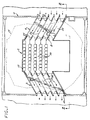
- Figure 1 is a top plane view of a prior art system illustrating passenger cabin 2 within the ride enclosure 4 with access bridges 6 in place.
- Cabin doors 8 and enclosure doors 10 are shown opened to the position in which they provide rapid access to passenger seats 12.
- bridge 6 retreats beyond the operating envelope 14 of the simulator, thereby providing a free movement of cabin 2 within its design parameters.
- access of the patrons is uni-directional from ingress doors 18 along aisles 20 on ingress bridge 22 to ingress cabin doors 24. Access is guided by ingress bridge rails 26 that define the aisles 20 on the bridge 22 and match with aisles 30 between the rows of patron seats 12.
- egress doors 32 in the cabin and enclosure egress doors 34 in the enclosure mate with egress bridge rails 36 to define egress aisles 38 on egress bridge 40.
- the cabin 2 is brought to a rest position at which time bridges 22 and 40 are deployed to a position in alignment with the openings defined by the cabin doors 8 and enclosure doors 10.
- the ride control computer actuates all of the egress doors, thereby providing an egress path for the patrons who have experienced the ride.
- the ingress doors are opened and the incoming load of passengers is provided access to the cabin preparatory to the ride beginning.
- the status is displayed on a panel for manual verification by the ride operator and, if all safety systems are secured, the ride control computer is allowed to proceed with retraction of the ingress-egress system after the ride operator has indicated to the ride control computer that he is at his station. Thereafter, the ride operator closes the doors and inputs a request to the ride control computer that the ride start. If the ride control computer (RCC) has received information from the appropriate sensors that the ride is safe to begin motion and that all passenger safety restraints are engaged, the RCC then retracts the bridges and begins the ride. Thereafter, the doors are closed and once the doors are closed, bridges 6 are retracted to a position outside of operating envelope 14. The ride control computer is provided an indication that the retraction process is complete and the beginning of the ride is then initiated.
- RCC ride control computer
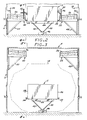
- Figure 2 is a cross-sectional elevational view showing cabin 2 at its loading rest position in enclosure 4. This loading position corresponding to the position assumed by the cabin when the hydraulic pressure that drives actuators 42 is removed and the weight of the cabin drives the actuators to their collapsed position.
- actuators 42 When actuators 42 have carried cabin 2 to its rest position, and bridges 22 and 40 have been deployed, doors 18, 30, 32 and 34 are then opened, providing access to cabin 2 in combination with rails 26 and 36.
- Actuators 42 operate cabin 2 through cabin structure 44, the actuators being supported from a basic structure 46 located in the floor of the enclosure.
- Bridges 22 and 40 are supported by structure 48 and 50 respectively, thereby providing a rigid and stable structure for ingress and egress of the passengers when the cabin is in its loading position and the access bridges are deployed.
- Aisle extensions 52 and 54 for the ingress and egress portions respectively, are designed to mate with bridges 22 and 40 to provide a smooth transition from the bridges to the cabin aisles without the necessity of directly interfacing the bridges with the side walls 56 and 58 respectivcely of the cabin structure.
- Figure 3 illustrates the arrangement of the access bridges after they have been retracted to positions outside of the operating envelope 14 of the passenger cabin 2.
- passenger cabin 2 is illustrated in the rest loading position in which actuators 42 have drawn down to their minimum height based on structure 46 and operating through cabin structure 44. It may be seen that the ingress and egress aisle extensions 52 and 54 remain attached to the cabin 2 and project from the cabin walls 56 and 58. Ingress structure 48 and egress structure 50 retract with the bridge as a unit when the bridge is pulled to its upper extremity in the retraction process.
- FIG 4 is a side elevational view at 4-4 of Figure 2 and illustrates egress bridge 40 in its deployed position.
- enclosure egress doors 34 are shown closed rather than deployed against egress bridge rails 36.
- Egress structure 50 shown here partially eliminated for the sake of clarity, supports egress bridge 40 away from the enclosure wall.
- a retraction mechanism generally designated 60 incorporates a drive system 62 which operates a cable drum 64 that winds cable 66 over a series of sheaves 68 to thereby retract or deploy bridge 40 between its deployed or retracted positions.
- FIG. 5 illustrates the bridge 40 retracted to its position outside of the operating envelope by use of retraction mechanism 60 incorporating drive system 62 driving cable drum 64.
- cables 66 are then wound around cable drum 64 and retract bridge 40 and supporting structure 50 to a retracted position when the cables 66 are wound over sheaves 68.
- the bridge structure may be completely withdrawn, leaving as the only obstruction the side wall of the ride housing.
- Figure 6 illustrates the mechanism by which the structure 50 and bridge 40 interface with guide rail 70 of ride housing 4.
- Figure 6 is a section at 6-6 of Figure 4 and shows that the structure interfaces through a vertical member 72 that incorporates rollers, generally designated 74, and a stop locating pad 76 to provide for accurate translation of the bridge 40 between its deployed and retracted systems.
- Figure 7 illustrates the arrangement of rollers 74 as they ride against guide rail 70.
- the upper roller 78 bears against surface 80 on guide rail 70, thereby preventing motion of the vertical member 72 inward into the enclosure.
- roller 82 varies against surface 84 on guide rail 70 to prevent lateral motion of the structure relative to the vertical guide rail 70. Both rollers are mounted upon bearings 86 that are attached to vertical member 72 of structure 50.
- Figure 8 illustrates a cross-sectional view of locating pad 76, illustrating how the male portion 88 of vertical member 72 fits into a mating female portion 90 mounted to the floor 92 of enclosure 4.
- Figure 9 is a cut-away view of a door 8 of the type used in the present invention.
- the latch mechanism generally designated 94, incorporates a linear actuator 96 that directly operates a locking pin 98 and operates a second locking pin 106.
- Locking pins 98 and 106 respectively interface with jamb plates 109 and 110 to lock the door when actuator 96 is engaged.
- Door 8 pivots about hinge 112 and is opened and closed by an actuator system generally designated 114.
- Figure 10 illustrates the actuation means to open and close the door.
- hinge member 118 is attached to door 8 by structural extensions 120.
- Lever arm 122 is fastened to hinge member 118 and is moved by linear actuator 124 in response to air admitted through fittings 126 which drive actuation rod 128 in a linear direction, thereby rotating the doors open and closed.
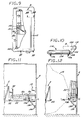
- FIG 11 illustrates a modification to the above system constituting an embodiment of the present invention in which bridge 22 is pivotally retracted against the walls of enclosure 4 rather than being withdrawn vertically.
- the relationship of rails 26 and pivot point 130 are arranged so that when the bridge is retracted, the rails 26 will not interfere with one another, nor will there be interference between any other portions of the bridge structure and the remaining structure within the enclosure or attached to the cabin.
- An actuator 132 pivotally attached to the wall at pivot point 134 and bridge structure 22 at the pivot point 136 is actuated to effect rotation of bridge 22 about pivot point 136 after ingress doors 18 and 30 have been closed.
- bridge 22 forms an extension of platform 138 and ingress aisle extension 52 to complete the access required to the cabin.
- Figure 12 illustrates bridge 22 in its retracted position against the outside wall after linear actuator 133 has been extended to pivot bridge 22 around pivot point 130.
- the bridge 22 has retracted outside of operating envelope 14 to provide free movement of cabin 2 throughout its operating range.
- Figure 13 illustrates a functional schematic of the electrical interfaces of the various basic components of the ingress-egress system with the ride control computer 16.
- the ride control computer 16 provides the primary means of controlling the door actuating sub-system 130, which incorporates both systems required to open and close the doors and the sensors required to provide the appropriate signals to the ride control computer that the doors are in position.
- the ingress and egress bridge system 132 incorporates both an ingress bridge lift system 134 and an egress bridge lift system 136. Provision is made for mutual operation of the lifts when the ride is not in use.
- An operator control console 140 is provided to allow the operator to interface with the ride control computer and to observe the interior of the cabin through the onboard surveilance camera 142.
- a similar control console 144 is provided for the tower operator, who acts as a backup observer.
- the monitor system monitors the Ride Control Computer(s) and generates fault messages for operations assistance and maintenance trouble-shooting.
- a hard copy printer 152 is provided to allow for the recording of the messages of the results of specific events during the ride.
- An uninterruptible power supply 154 is provided to assure that any interruption in the normal power supply to the ride control computer and the other systems will allow the drive system to safely shut down the ride.
- the system safety sensors 156 provide input to the ride control computer to provide a positive indication that all doors are closed and occupied seat restraints are latched prior to initiation of the ride.
- the ride control computer sequences the deployment of the ingress and egress bridges prior to the opening of the access doors that meet with the bridges. After the doors have been opened to meet with deployed ingress and egress bridges and the passengers have taken their seats, the doors are closed by the operator and the bridges are retracted to their safe positions outside of the operating envelope of the ride cabin. Thereafter, the system safety sensors provide input to the ride control computer that all doors have been properly closed and bridges have been retracted and the passenger restraints are latched for the occupied seats. When the operator manually requests a ride start and the Ride Control Computer determines that it is safe to do so, the ride control computer can begin the amusement ride.
- the present invention provides a highly safe, reliable, efficient and economical means of rapidly accessing a moving base simulator used as an amusement ride.
Landscapes
- Management, Administration, Business Operations System, And Electronic Commerce (AREA)
- Seats For Vehicles (AREA)
- Vehicle Step Arrangements And Article Storage (AREA)
- Power-Operated Mechanisms For Wings (AREA)
Description
- Amusement rides that utilize passenger cabins which are capable of movement with multiple degrees of freedom (roll, pitch, yaw, vertical, lateral and longitudinal motion) have recently become popular due to their ability to provide exciting rides in relatively small areas. US-4,066,256 discloses an example of such an amusement ride. However, such amusement rides present many difficulties associated with their safe operation and economics.
- Previous amusement rides that utilized tracked vehicles used loading facilities which incorporated loading platforms located in a designated loading area adjacent to the tracks upon which the vehicle runs. Such a system utilizes direct access of the patron into the movable vehicle by allowing the patron to step directly into the vehicle when it is brought to rest in the loading area. Thereafter, the operator of the ride manually assures that safety systems, such as seatbelts and other restraints, are engaged prior to departure of the vehicle from the loading platform area.
- Similarly, non-tracked rides such as ferris wheels and other rotary or oscillating rides have utilized a waiting area and loading zone to which the passenger vehicles are progressively brought, stopped and loaded.
- While such access systems have proven useful and practical for a wide variety of relatively simple rides, they are relatively limited in their applicability due to the fact that the vehicle must be brought to a slow and controlled stop next to the boarding platform on which the next load of patrons is waiting. However, the stationary loading platform approach is not readily applicable to non-tracked vehicles that must operate at high speed in close proximity to the platform, especially if such vehicles are capable of movement in a direction lateral to the loading platform.
- The adaptation of multiple degree of freedom motion simulators as a basis for amusement rides has presented a variety of problems, among them rapid, economical and safe means of providing access by patrons to the ride. Amusement rides which use cabin vehicles that are maneuvered in multiple degrees of freedom must be enclosed within a structure which prevents access to the operating envelope of the vehicle by patrons or other unauthorized persons in order to prevent the risk of severe injury which would occur should a person be trapped within the operating envelope of the vehicle once the ride has begun. Large cabin vehicles of the type that are utilized in theme parks and other major attractions present enormous risks in that the potential force and velocity of the rides cannot be overcome by any human force and, once set in motion, are not susceptable to immediate cesation of all motion when operating at high speed without injury to the operators, structure, occupants, or some combination thereof.
- Furthermore, such moving cabin rides represent a very large investment due to their use of hydraulic and electronic power systems and their extensive use of advanced technology, including computers. Such systems were developed, in part, from simulators used to train pilots and other operators of expensive vehicles, primarily to avoid the risks associated with losing such an expensive vehicle during experimental or training exercises. For that reason, rapid ingress and egress of a large number of passengers was neither necessary nor desirable, since the simulator could only be effectively and economically used by a relatively small number of people over a relatively large period of time, and the simulator was much less expensive to use than the aircraft or other vehicle being simulated. The first uses of such moving simulators as amusement rides incorporated the simple door and access plank developed for the simulators, but the economics for such an installation were not justifiable to major theme parks in light of the relatively limited space available for such systems, the cost of the equipment and physical plant associated with the installation and the probability of client alienation associated with excess wait time to enjoy the attraction. Furthermore, the relatively simple loading systems available for amusement rides could not be adapted to the simulator based systems, since the operating enevelope of the simulator could not be intruded into, and such systems as were available were all deficient in providing high capacity access without interfering with the operating envelope.
- For these reasons there remains a need for a rapid, economical, safe and relatively high capacity ingress-egress system for a moving cabin and other high energy, high coat amusement rides that present the above requirements.
- Ingress-egress systems for amusement rides must provide rapid and easy access to the ride in a carefully controlled environment and still prevent unnecessary risk of harm to the patron. When these requirements are combined with the use of a large moving cabin simulator that is capable of movement in six degrees of freedom, with the resultant large envelope which must be cleared prior to activation of the simulator, conventional and simple methods of access to such amusement rides become impractical. Furthermore, reliance upon a human operator to determine that seat belts or other restraints are physically engaged prior to activation of the moveable cabin, which can produce high accelerations about all axes, is insufficient to guarantee safety of the patron during the ride. The damage which may occur in the event that a partial failure or differential activation of the access system were to occur emphasizes the fact that simple patron access systems of the type previously used for such amusement rides are inadequate in today's environment of higher cost effectiveness and safety requirements. Furthermore, the great cost of multiple degree of freedom simulators to be used as amusement rides justifies a higher capacity access system, even though it may be more complex and costly than a simple system.
- During 1987 there was disclosed in the United States by public use a system for providing passenger ingress and egress in an amusement ride having a passenger cabin movable within an operating envelope and an enclosure outside the operating envelope, said system comprising:
a plurality of first doors arranged on surfaces of said cabin, said doors providing access to ingress and egress paths within said cabin;
a plurality of second doors arranged on surfaces of said enclosure, said second doors being substantially in alignment with said first doors when said cabin is in a loading position;
retractable bridge means movable between a deployed position in which the bridge means provide access between the first and second doors and a retracted position in which the bridge means are retracted outside of the operating envelope; and
control means for controlling and coordinating the opening of said first doors and said second doors and the retraction and deployment of said bridge means so as to enable rapid passenger ingress and egress to and from said cabin when said cabin is in said loading position. - Such a system is described below with reference to Figures 1 to 5 in which a retraction mechanism operates a cable drum that winds cable over a series of sheaves to retract or deploy a bridge between deployed or retracted positions.
- A system in accordance with the present invention is characterised by the bridge means comprising a substantially horizontal platform within said enclosure having one end connected to said enclosure under said second doors and a free end located outside the operating envelope of said cabin; and
a bridge pivotally connected to the free end of said platform and having pivoting means operable to pivotally move the bridge between a retracted position in which said bridge is pivotally retracted against said enclosure and above said platform outside the operating envelope of said cabin and a deployed position in which said bridge is pivoted away from said enclosure to provide access from said platform to said cabin through said first and second doors when said cabin is in said loading position. - In a preferred embodiment of the present invention a combination of high speed retractable access platforms is combined with a door configuration in the cabin and enclosure structure, and interlocking control systems for the door platforms and restraint systems that provide previously unavailable levels of patron throughput and safety for multiple degree of freedom moving base amusement rides.
- Preferably, a plurality of doors is arranged on opposite sides of the cabin at each end of the aisles adjacent each row of seats in the cabin. The doors are activated by a control system that coordinates their opening with the deployment of high speed movable access bridges that are retracted beyond the operating envelope of the moving base amusement ride when it is in operation. In a preferred embodiment, the floor of the amusement ride is either stepped or sloped downwards from back to front to allow unrestricted viewing by the patron of a scene projected in the front of the moving cabin. Each of the access aisles are thus displaced vertically in step-wise fashion from the back of the cabin to the front and their respective access doors are positioned so that their bottom edges are aligned with the surface of the aisle of their respective row.
- Immediately after the passenger cabin is brought to a rest at the completion of the ride, the bridges are rapidly moved from their rest position outside of the operating envelope of the cabin to a position in alignment with the doors. The bridges are configured so that their respective entry aisles are aligned vertically and laterally with the position of the doors and their associated aisles. When the central ride control computer is provided with sensor information that the access bridges have been positioned in alignment with appropriate indexing positions, the doors are opened and patrons who have enjoyed the ride may move out of the cabin through one set of doors while those entering the amusement ride are granted entrance to the cabin through the doors on the opposite side of the cabin. The movable loading bridges, in turn, are lowered and aligned with the movable cabin and the enclosure doors to create a path for ingress and egress to the cabin via the movable bridges. The doors to the stationary loading ramps outside the enclosure are likewise controlled by the ride control computer and are opened after the movable bridges have come to rest in alignment with the cabin doors and the enclosure doors upon completion of the ride.
- Thus, after the ride has been completed, the invention provides for a tightly controlled sequence of stopping the passenger cabin, deploying the high speed access bridges and opening the doors in a coordinated fashion after the bridges, cabin and outer doors are properly aligned, thereby allowing the patrons to proceed via the aisles between the seats into and out of the cabin via the ingress and egress doors located on opposite sides of the cabin.
- After the entering patrons have been seated, a central control system will not allow initiation of the cabin closing sequence prior to the beginning of the ride until all of the passenger restraints for occupied seats are engaged. Thus, the sequence initiating the beginning of the ride can only begin after the passengers are positively restrained. A control panel illustrating the status of the restraints may also be provided so that a human operator may cross check the system operation and ascertain the location of disengaged restraint systems. After the restraint systems are engaged, the operator leaves the passenger cabin and, upon reaching his station outside of the ride enclosure, actuates a switch which begins the closing sequence. The doors to the cabin and to the external bridges are closed; then the high speed retractable loading bridges are retracted out of the operating envelope of the cabin and the ride begins.
- It may be seen from the above description that the present invention provides a highly automated and efficient means of providing ingress and egress to moving cabin amusement rides while providing a high degree of safety and automation necessary for rides which are capable of rapid motion and multiple degrees of freedom within an enclosed area. In order to increase the inherent safety associated with the invention, failsafe design and redundancy is provided in all of the critical control systems and emergency stop functions are provided in the event of a failure of any critical system.
- Other features and advantages of the invention will become apparent from the following detailed description taken in conjunction with the accompanying drawings, which illustrate, by way of example, the features of the invention.
- Figure 1 is a top elevational view of the prior art amusement ride ingress-egress system disclosed by public use in 1987, illustrating the relationship of the passenger cabin, the ride enclosure and the ingress-egress system components;
- Figure 2 is a cross-section of the ingress-egress system of Figure 1 at 2-2;
- Figure 3 is a cross-section similar to Figure 2, illustrating the arrangement of the access bridges when they are retracted beyond the operating envelope of the passenger cabin;
- Figure 4 is a side elevational view at section 4-4 of Figure 2, showing the retraction mechanism for the access bridges;
- Figure 5 is a side elevational cross-section similar to Figure 4, illustrating the position of the access bridges when they are in their retracted position;
- Figure 6 is a section at 6-6 of Figure 4 illustrating the rail and guide system for the access bridges in the guide rails in the side of the ride housing;
- Figure 7 is a section at 7-7 of the guide rail system illustrating the guide rollers and their relationship to the guide rail system;
- Figure 8 is a section at 8-8 of Figure 6, illustrating the stop locating pad for the access bridge system;
- Figure 9 is a cut-away elevational view of an access door illustrating the door locking mechanism;
- Figure 10 is an illustration of the door actuation system as viewed from 10-10 of Figure 9;
- Figure 11 is an elevation of an amusement ride ingress-egress system in accordance with the present invention utilizing a pivoting drawbridge system;
- Figure 12 illustrates the drawbridge system of Figure 11 in its retracted position; and
- Figure 13 is an operational schematic diagram illustrating the relationship of the various electromechanical and electronic portions of an amusement ride according to the present invention.
- The system described below including the modification of Figures 11 and 12 in accordance with the present invention provides a means of rapid and high volume access to a
passenger cabin 2 from the exterior of structure 4 by use ofretractable bridges 6 that match withcabin doors 8 andenclosure doors 10 to provide controlled access to patron's seats 12. Thecabin 2 is capable of movement in multiple degrees of freedom (roll, pitch, yaw, x,y,z) through operatingenvelope 14. Aride control computer 16 monitors sensors and controls the safety interlock system that provides the required deployment sequence of the ingress-egress system and prevents the starting of the ride until each passenger that occupies a seat has fastened a safety restraint and the ingress-egress system has been retracted to an area outside the envelope. Thus, the present invention provides the benefits of very high throughput while limiting the potential for damage to the ride, its access system or the patrons. - The availability of multiple degree of freedom flight simulators has created the opportunity to provide amusement rides that can expose the passengers to a wide variety of motion cues without leaving a single central facility. When the capability to provide a wide variety of visual cues is included, the potential for such simulators as amusement rides is very promising. However, simulators have generally been designed to provide training for aircraft and other expensive vehicles and most of this training was to be provided to as relatively small number of people who were to use the simulator for a relatively larger period of time. The requirement to rapidly turn over the number of people to use such a simulator for an approximately 5 minute amusement ride created new pressures previously ignored or unrecognised to allow rapid and safe access of the patrons to the passenger cabin during the change over between shows. Since such a simulator is extremely expensive, the entire economics of employing a six degree of freedom simulator as an amusement ride rested with the ability to provide rapid ingress and egress by patrons in a safe and reliable manner. The present invention provides such safe and reliable access without in any way inhibiting the capabilities of the simulator and its use as an amusement ride.
- Figure 1 is a top plane view of a prior art system illustrating
passenger cabin 2 within the ride enclosure 4 withaccess bridges 6 in place.Cabin doors 8 andenclosure doors 10 are shown opened to the position in which they provide rapid access to passenger seats 12. When retracted,bridge 6 retreats beyond the operatingenvelope 14 of the simulator, thereby providing a free movement ofcabin 2 within its design parameters. As shown by the arrows, access of the patrons is uni-directional fromingress doors 18 alongaisles 20 oningress bridge 22 toingress cabin doors 24. Access is guided by ingress bridge rails 26 that define theaisles 20 on thebridge 22 and match withaisles 30 between the rows of patron seats 12. Similarly,egress doors 32 in the cabin andenclosure egress doors 34 in the enclosure mate with egress bridge rails 36 to defineegress aisles 38 onegress bridge 40. In the sequence of operations according to the invention, thecabin 2 is brought to a rest position at which time bridges 22 and 40 are deployed to a position in alignment with the openings defined by thecabin doors 8 andenclosure doors 10. When the bridges are at the appropriate position and the sensors so indicate, the ride control computer actuates all of the egress doors, thereby providing an egress path for the patrons who have experienced the ride. As soon as practicable thereafter, the ingress doors are opened and the incoming load of passengers is provided access to the cabin preparatory to the ride beginning. When all the entering passengers have been seated and have actuated their seat restraints (not shown here), the status is displayed on a panel for manual verification by the ride operator and, if all safety systems are secured, the ride control computer is allowed to proceed with retraction of the ingress-egress system after the ride operator has indicated to the ride control computer that he is at his station. Thereafter, the ride operator closes the doors and inputs a request to the ride control computer that the ride start. If the ride control computer (RCC) has received information from the appropriate sensors that the ride is safe to begin motion and that all passenger safety restraints are engaged, the RCC then retracts the bridges and begins the ride. Thereafter, the doors are closed and once the doors are closed, bridges 6 are retracted to a position outside of operatingenvelope 14. The ride control computer is provided an indication that the retraction process is complete and the beginning of the ride is then initiated. - Figure 2 is a cross-sectional elevational
view showing cabin 2 at its loading rest position in enclosure 4. This loading position corresponding to the position assumed by the cabin when the hydraulic pressure that drivesactuators 42 is removed and the weight of the cabin drives the actuators to their collapsed position. When actuators 42 have carriedcabin 2 to its rest position, and bridges 22 and 40 have been deployed,doors cabin 2 in combination withrails Actuators 42 operatecabin 2 throughcabin structure 44, the actuators being supported from abasic structure 46 located in the floor of the enclosure.Bridges structure Aisle extensions bridges side walls - Figure 3 illustrates the arrangement of the access bridges after they have been retracted to positions outside of the operating
envelope 14 of thepassenger cabin 2. Here,passenger cabin 2 is illustrated in the rest loading position in which actuators 42 have drawn down to their minimum height based onstructure 46 and operating throughcabin structure 44. It may be seen that the ingress andegress aisle extensions cabin 2 and project from thecabin walls Ingress structure 48 andegress structure 50 retract with the bridge as a unit when the bridge is pulled to its upper extremity in the retraction process. - Figure 4 is a side elevational view at 4-4 of Figure 2 and illustrates
egress bridge 40 in its deployed position. In this illustration,enclosure egress doors 34 are shown closed rather than deployed against egress bridge rails 36.Egress structure 50, shown here partially eliminated for the sake of clarity, supportsegress bridge 40 away from the enclosure wall. A retraction mechanism generally designated 60 incorporates adrive system 62 which operates acable drum 64 that windscable 66 over a series ofsheaves 68 to thereby retract or deploybridge 40 between its deployed or retracted positions. - Figure 5 illustrates the
bridge 40 retracted to its position outside of the operating envelope by use ofretraction mechanism 60 incorporatingdrive system 62 drivingcable drum 64. As previously described,cables 66 are then wound aroundcable drum 64 and retractbridge 40 and supportingstructure 50 to a retracted position when thecables 66 are wound oversheaves 68. As may be seen from this view, by use of this mechanism the bridge structure may be completely withdrawn, leaving as the only obstruction the side wall of the ride housing. - Figure 6 illustrates the mechanism by which the
structure 50 andbridge 40 interface withguide rail 70 of ride housing 4. Figure 6 is a section at 6-6 of Figure 4 and shows that the structure interfaces through avertical member 72 that incorporates rollers, generally designated 74, and astop locating pad 76 to provide for accurate translation of thebridge 40 between its deployed and retracted systems. - Figure 7 illustrates the arrangement of
rollers 74 as they ride againstguide rail 70. The upper roller 78 bears againstsurface 80 onguide rail 70, thereby preventing motion of thevertical member 72 inward into the enclosure. Similarly,roller 82 varies againstsurface 84 onguide rail 70 to prevent lateral motion of the structure relative to thevertical guide rail 70. Both rollers are mounted uponbearings 86 that are attached tovertical member 72 ofstructure 50. - Figure 8 illustrates a cross-sectional view of locating
pad 76, illustrating how the male portion 88 ofvertical member 72 fits into a matingfemale portion 90 mounted to thefloor 92 of enclosure 4. Thus, when the structure of thebridge 40 is in its deployed position, the bridge is positively located by locatingpad 76. - Figure 9 is a cut-away view of a
door 8 of the type used in the present invention. The latch mechanism, generally designated 94, incorporates alinear actuator 96 that directly operates a locking pin 98 and operates asecond locking pin 106. Locking pins 98 and 106 respectively interface withjamb plates 109 and 110 to lock the door whenactuator 96 is engaged.Door 8 pivots abouthinge 112 and is opened and closed by an actuator system generally designated 114. - Figure 10 illustrates the actuation means to open and close the door. As discussed above,
hinge member 118 is attached todoor 8 bystructural extensions 120. Lever arm 122 is fastened to hingemember 118 and is moved bylinear actuator 124 in response to air admitted throughfittings 126 which driveactuation rod 128 in a linear direction, thereby rotating the doors open and closed. - Figure 11 illustrates a modification to the above system constituting an embodiment of the present invention in which
bridge 22 is pivotally retracted against the walls of enclosure 4 rather than being withdrawn vertically. Here, the relationship ofrails 26 andpivot point 130 are arranged so that when the bridge is retracted, therails 26 will not interfere with one another, nor will there be interference between any other portions of the bridge structure and the remaining structure within the enclosure or attached to the cabin. Anactuator 132 pivotally attached to the wall atpivot point 134 andbridge structure 22 at thepivot point 136 is actuated to effect rotation ofbridge 22 aboutpivot point 136 afteringress doors position bridge 22 forms an extension ofplatform 138 andingress aisle extension 52 to complete the access required to the cabin. - Figure 12 illustrates
bridge 22 in its retracted position against the outside wall after linear actuator 133 has been extended to pivotbridge 22 aroundpivot point 130. Thus, thebridge 22 has retracted outside of operatingenvelope 14 to provide free movement ofcabin 2 throughout its operating range. - Figure 13 illustrates a functional schematic of the electrical interfaces of the various basic components of the ingress-egress system with the
ride control computer 16. Theride control computer 16 provides the primary means of controlling thedoor actuating sub-system 130, which incorporates both systems required to open and close the doors and the sensors required to provide the appropriate signals to the ride control computer that the doors are in position. Similarly, the ingress andegress bridge system 132 incorporates both an ingressbridge lift system 134 and an egressbridge lift system 136. Provision is made for mutual operation of the lifts when the ride is not in use. - An
operator control console 140 is provided to allow the operator to interface with the ride control computer and to observe the interior of the cabin through theonboard surveilance camera 142. A similar control console 144 is provided for the tower operator, who acts as a backup observer. The monitor system monitors the Ride Control Computer(s) and generates fault messages for operations assistance and maintenance trouble-shooting. A hard copy printer 152 is provided to allow for the recording of the messages of the results of specific events during the ride. Anuninterruptible power supply 154 is provided to assure that any interruption in the normal power supply to the ride control computer and the other systems will allow the drive system to safely shut down the ride. - The
system safety sensors 156 provide input to the ride control computer to provide a positive indication that all doors are closed and occupied seat restraints are latched prior to initiation of the ride. Thus, the ride control computer sequences the deployment of the ingress and egress bridges prior to the opening of the access doors that meet with the bridges. After the doors have been opened to meet with deployed ingress and egress bridges and the passengers have taken their seats, the doors are closed by the operator and the bridges are retracted to their safe positions outside of the operating envelope of the ride cabin. Thereafter, the system safety sensors provide input to the ride control computer that all doors have been properly closed and bridges have been retracted and the passenger restraints are latched for the occupied seats. When the operator manually requests a ride start and the Ride Control Computer determines that it is safe to do so, the ride control computer can begin the amusement ride. - While those skilled in the art will appreciate that a variety of programs and computers may be used to achieve the results required of the
ride control computer 16, a practical embodiment of the present invention incorporates the use of a double redundant programmable controllers. Those skilled in the art will appreciate that a variety of computers and programming languages may be used to provide the sequences of operation and the safety interlocks described above. - From the above it may be seen that the present invention provides a highly safe, reliable, efficient and economical means of rapidly accessing a moving base simulator used as an amusement ride.
Claims (15)
- A system for providing passenger ingress and egress in an amusement ride having a passenger cabin (2) movable within an operating envelope (14) and an enclosure (4) outside the operating envelope, said system comprising:
a plurality of first doors (8) arranged on surfaces (56,58) of said cabin, said doors providing access to ingress and egress paths (30) within said cabin;
a plurality of second doors (10) arranged on surfaces of said enclosure, said second doors being substantially in alignment with said first doors when said cabin is in a loading position;
retractable bridge means (22) movable between a deployed position in which the bridge means provide access between the first and second doors and a retracted position in which the bridge means are retracted outside of the operating envelope; and
control means (16) for controlling and coordinating the opening of said first doors and said second doors and the retraction and deployment of said bridge means so as to enable rapid passenger ingress and egress to and from said cabin when said cabin is in said loading position,
characterised by the bridge means comprising a substantially horizontal platform (138) within said enclosure having one end connected to said enclosure under said second doors and a free end located outside the operating envelope of said cabin; and
a bridge (22) pivotally connected to the free end of said platform and having pivoting means (132) operable to pivotally move the bridge between a retracted position in which said bridge is pivotally retracted against said enclosure and above said platform outside the operating envelope of said cabin and a deployed position in which said bridge is pivoted away from said enclosure to provide access from said platform to said cabin through said first and second doors when said cabin is in said loading position. - The system as claimed in claim 1 wherein said pivoting means comprises an actuator (132) pivotally attached to said enclosure and to said bridge to effect rotation of said bridge about the free end of said platform (138) during pivoting of said bridge between said retracted and said deployed positions.
- The system of claim 2 wherein said actuator is a linear actuator having one end pivotally connected to said enclosure underneath said platform (138) and another end pivotally attached to said bridge adjacent to the free end of said platform.
- The system of claim 1 wherein said bridge (22) and said platform (138) are provided with rails (26) such that, during pivoting of said bridge between said retracted and said deployed positions, the rails of said bridge will not interfere with the rails of said platform.
- The system of claim 1 wherein said first doors (8) of said cabin comprise a plurality of ingress doors (24) located on a first surface (56) of said cabin (2) and a plurality of egress doors (32) located on a second surface (58) of said cabin.
- The system of claim 5 wherein said ingress and egress doors (24,32) of said cabin are aligned with said ingress and egress paths (30) in said cabin.
- The system of claim 5 wherein said second doors (10) in said enclosure (4) comprise a plurality of ingress doors (18) located on a first surface of said enclosure and a plurality of egress doors (34) located on a second surface of said enclosure.
- The system of claim 7 wherein said bridge means comprise a pivotable ingress bridge (22) pivoting between a retracted position outside the operating envelope of said cabin and a deployed position aligned with and connecting said ingress doors (24) of said cabin and said ingress doors (18) of said enclosure when said cabin is in said loading position, and a pivotable egress bridge (40) pivoting between a retracted position outside the operating envelope of said cabin and a deployed position aligned with and connecting said egress doors (32) of said cabin and said egress doors (34) of said enclosure when said cabin is in said loading position.
- The system of claim 8 wherein said control means (16) coordinates and controls the pivoting of said bridges (22) to the deployed position and the opening of all of said doors (18,24,32,34) to provide access to said cabin when said cabin is in said loading position and to close all of said doors and to pivotally retract said bridges to the retracted position in a coordinated manner to provide a clear path for motion of said cabin.
- The system of claim 7 wherein said cabin includes a plurality of seats (12) and said system further comprises restraint means for restraining passengers in said seats when said cabin is in motion.
- The system of claim 10 wherein said control means further controls said restraint means and prevents release of said restraint means when said cabin is in motion.
- The system of claim 10 wherein said control means controls and coordinates the actuation of said doors, said bridges and said restraint means to provide a system affording rapid passenger ingress and egress to said cabin after it has come to said loading position and to prevent deployment of said system or release of said restraint means when said cabin is in motion.
- The system of claim 12 wherein said control means comprises an electronic computer.
- The system of claim 13 wherein said electronic computer further comprises an electronic digital computer.
- The system of claim 1 wherein said cabin is capable of motion in multiple degrees of freedom within said enclosure.
Applications Claiming Priority (2)
| Application Number | Priority Date | Filing Date | Title |
|---|---|---|---|
| US07/141,933 US5021954A (en) | 1988-01-11 | 1988-01-11 | System and method of providing passenger ingress and egress in an amusement ride |
| US141933 | 1988-01-11 |
Publications (3)
| Publication Number | Publication Date |
|---|---|
| EP0324567A2 EP0324567A2 (en) | 1989-07-19 |
| EP0324567A3 EP0324567A3 (en) | 1989-11-29 |
| EP0324567B1 true EP0324567B1 (en) | 1993-10-27 |
Family
ID=22497867
Family Applications (1)
| Application Number | Title | Priority Date | Filing Date |
|---|---|---|---|
| EP89300151A Expired - Lifetime EP0324567B1 (en) | 1988-01-11 | 1989-01-09 | Amusement ride ingress-egress system |
Country Status (5)
| Country | Link |
|---|---|
| US (1) | US5021954A (en) |
| EP (1) | EP0324567B1 (en) |
| JP (1) | JP2853862B2 (en) |
| DE (1) | DE68910137T2 (en) |
| ES (1) | ES2048278T3 (en) |
Families Citing this family (18)
| Publication number | Priority date | Publication date | Assignee | Title |
|---|---|---|---|---|
| US5161104A (en) * | 1988-01-11 | 1992-11-03 | The Walt Disney Company | Amusement ride having pivotable ingress-egress bridges |
| US5253166A (en) * | 1991-03-29 | 1993-10-12 | Disc Corporation | Pre-ticket travel reservation record keeping system |
| EP0934106A1 (en) * | 1994-01-24 | 1999-08-11 | Skycoaster, Inc. | Swing type amusement ride with pendulum damper |
| NL1009781C2 (en) * | 1998-07-31 | 2000-02-01 | Vekoma Tech Bv | Entertainment device and luggage handling device suitable for such an entertainment device. |
| US6428419B1 (en) * | 2000-04-11 | 2002-08-06 | Universal City Studios, Inc. | Amusement attraction with moveable floor |
| DE10350059B4 (en) * | 2003-10-27 | 2011-02-10 | Stefan Hinzmann | event arrangement |
| US7884848B2 (en) * | 2005-05-25 | 2011-02-08 | Ginther Mark E | Viewing environment and recording system |
| EP2248756B1 (en) * | 2006-04-28 | 2015-06-03 | Electronic Theatre Controls, Inc. | Lift system |
| RU2492904C2 (en) | 2007-11-08 | 2013-09-20 | Электроник Тиэте Контролз, Инк. | Systems of lifting assembly and methods |
| EP2910514B1 (en) | 2009-11-18 | 2016-10-19 | Electronic Theatre Controls, Inc. | Lift assembly systems and methods |
| US8225555B2 (en) * | 2010-02-25 | 2012-07-24 | Falcon's Treehouse, L.L.C. | Motion simulator theater with suspended seating |
| DE102010053686B3 (en) * | 2010-12-08 | 2012-01-26 | Grenzebach Maschinenbau Gmbh | Autonomous safety system for the users of vehicle simulators or flight simulators, methods for the safe use of such simulators, a computer program for carrying out the method and a machine-readable carrier with the program code. |
| US10183850B2 (en) | 2012-12-21 | 2019-01-22 | Electronic Theatre Controls, Inc. | Compact hoist system |
| JP6178664B2 (en) * | 2013-08-12 | 2017-08-09 | 株式会社ユー・エス・ジェイ | Safety support device for amusement vehicles |
| JP6261274B2 (en) * | 2013-10-09 | 2018-01-17 | 株式会社ユー・エス・ジェイ | Safety support device for amusement vehicles |
| US9600999B2 (en) * | 2014-05-21 | 2017-03-21 | Universal City Studios Llc | Amusement park element tracking system |
| US10252736B2 (en) * | 2015-11-25 | 2019-04-09 | Coordem Transport Tech. Co., Ltd. | Method and system for controlling grade of automation of train operation |
| DE202021103837U1 (en) | 2021-07-19 | 2022-10-25 | Raw Tex International Establishment | wobble arrangement |
Citations (1)
| Publication number | Priority date | Publication date | Assignee | Title |
|---|---|---|---|---|
| US4066256A (en) * | 1975-11-17 | 1978-01-03 | Future General Corporation | Amusement ride |
Family Cites Families (27)
| Publication number | Priority date | Publication date | Assignee | Title |
|---|---|---|---|---|
| US797095A (en) * | 1904-05-07 | 1905-08-15 | Edward C Boyce | Marine-illusion apparatus. |
| US809589A (en) * | 1905-05-05 | 1906-01-09 | Edwin S Timmons | Amusement apparatus. |
| US818304A (en) * | 1905-06-02 | 1906-04-17 | Robert Fleming | Aerial ladder. |
| US892070A (en) * | 1906-08-03 | 1908-06-30 | Francis W Murphy | Amusement device. |
| US872627A (en) * | 1907-08-09 | 1907-12-03 | Charles C Keen | Amusement device. |
| US1037474A (en) * | 1911-07-20 | 1912-09-03 | Jacob Gunzendorfer | Amusement apparatus. |
| FR452235A (en) * | 1912-12-20 | 1913-05-10 | Gustave Van Den Kerckhove | Exhibition or fair attraction |
| GB188158A (en) * | 1921-10-04 | 1922-11-09 | Noak S Ark Corp | Improvements in amusement apparatus |
| GB705374A (en) * | 1950-10-17 | 1954-03-10 | Century Theatre Ltd | An improved mobile hall or like structure |
| US2756686A (en) * | 1950-10-20 | 1956-07-31 | Adamson Stephens Mfg Co | Transportation apparatus |
| US2778674A (en) * | 1953-12-08 | 1957-01-22 | Stadler Hurter & Company | Airport and transfer buses |
| US2750135A (en) * | 1954-06-04 | 1956-06-12 | Whiting Corp | Apparatus for facilitating the loading and unloading of aircraft passengers and cargo at airports |
| US3006008A (en) * | 1956-10-12 | 1961-10-31 | Loomis Machine Company | Dock board construction used as self adjusting bridge between truck and dock |
| US3185108A (en) * | 1963-07-10 | 1965-05-25 | C F Butz Engineering | Pedestrian carrier |
| US3628829A (en) * | 1966-03-09 | 1971-12-21 | Morton L Heilig | Experience theater |
| US3633904A (en) * | 1970-01-13 | 1972-01-11 | Sanseiyusoki Co Ltd | Rotary elevator observation tower |
| US3865041A (en) * | 1973-04-16 | 1975-02-11 | Arrow Dev Co | Rotary platform vehicle passenger loading system |
| US4084713A (en) * | 1976-05-03 | 1978-04-18 | Collins Industries, Inc. | Vehicle wheelchair ramp |
| FR2377347A1 (en) * | 1976-12-29 | 1978-08-11 | Mac Gregor International Sa | DEVICE FOR FOLDING AND DEPLOYING A MOBILE ACCESS RAMP |
| US4133067A (en) * | 1977-12-16 | 1979-01-09 | Bennett Ronald W | Articulating gangway |
| SE419329B (en) * | 1978-09-06 | 1981-07-27 | Jernkonstruktioner Ab | HIGH AND SUBSTANTABLE BRIDGE FOR CONNECTING TO FERRIES AND CARGOING, PREFERRED WITH OWN CLAP |
| US4222140A (en) * | 1979-02-23 | 1980-09-16 | F. C. Schaffer & Associates, Inc. | Boarding platform |
| US4425851A (en) * | 1981-02-17 | 1984-01-17 | Long Alvin L | High speed passenger transfer vehicle |
| US4473916A (en) * | 1982-02-24 | 1984-10-02 | Gec Mechanical Handling Limited | Access means |
| JPS6168074A (en) * | 1984-09-10 | 1986-04-08 | 三菱電機株式会社 | Imaging equipment having motion mechanism |
| CH664502A5 (en) * | 1985-09-17 | 1988-03-15 | Giovanola Freres Sa | PASSENGER RESTRAINT IN STANDING POSITION ON VEHICLE ON RAILS. |
| CH672461A5 (en) * | 1986-12-18 | 1989-11-30 | Von Roll Transportsysteme |
-
1988
- 1988-01-11 US US07/141,933 patent/US5021954A/en not_active Expired - Fee Related
-
1989
- 1989-01-09 ES ES89300151T patent/ES2048278T3/en not_active Expired - Lifetime
- 1989-01-09 DE DE89300151T patent/DE68910137T2/en not_active Expired - Fee Related
- 1989-01-09 EP EP89300151A patent/EP0324567B1/en not_active Expired - Lifetime
- 1989-01-11 JP JP294889A patent/JP2853862B2/en not_active Expired - Lifetime
Patent Citations (1)
| Publication number | Priority date | Publication date | Assignee | Title |
|---|---|---|---|---|
| US4066256A (en) * | 1975-11-17 | 1978-01-03 | Future General Corporation | Amusement ride |
Also Published As
| Publication number | Publication date |
|---|---|
| DE68910137D1 (en) | 1993-12-02 |
| ES2048278T3 (en) | 1994-03-16 |
| DE68910137T2 (en) | 1994-03-10 |
| JP2853862B2 (en) | 1999-02-03 |
| JPH025988A (en) | 1990-01-10 |
| US5021954A (en) | 1991-06-04 |
| EP0324567A2 (en) | 1989-07-19 |
| EP0324567A3 (en) | 1989-11-29 |
Similar Documents
| Publication | Publication Date | Title |
|---|---|---|
| US5161104A (en) | Amusement ride having pivotable ingress-egress bridges | |
| US5021954A (en) | System and method of providing passenger ingress and egress in an amusement ride | |
| US8328137B2 (en) | Emergency exit hatch for exiting a cabin module in an emergency and entering the same | |
| US4804308A (en) | Wheelchair lift | |
| RU2589659C1 (en) | Flying cinema | |
| EP2649604B1 (en) | Autonomous safety system for the users of vehicle simulators | |
| EP1833585B1 (en) | Amusement park attraction | |
| EP3356276A1 (en) | Vertically and horizontally mobile elevator cabins | |
| WO1990001013A1 (en) | High-rise fire fighting and rescue system | |
| US4039091A (en) | Elevator type bus boarder | |
| WO2021028096A1 (en) | A safety apparatus for an elevator cabin moving in a horizontal direction | |
| JP2024014847A (en) | Safety cockpit, flight equipment, automobile, running equipment, and running method | |
| JP5843495B2 (en) | Home door device | |
| CA3232786A1 (en) | Rotating dark ride systems and methods | |
| CA2189923A1 (en) | Fail-safe movement of elevator cabs between car frames and landings | |
| US12479479B2 (en) | Emergency front door for pneumatically-propelled vehicles on an elevated track | |
| CN114174143A (en) | Platform shield | |
| JPS6348618Y2 (en) | ||
| KR101877956B1 (en) | Heliport Elevator Capable of Improving Balance Safety and Wind Pressure Resistance and Preventing Infiltration of Rainwater and Icing | |
| CN114919751B (en) | Escape device for cabin, cabin assembly, vehicle and escape method | |
| EP0700701A1 (en) | Public entertainment system which creates the illusion of movement | |
| CN218793880U (en) | Flight cinema rides equipment with emergency rescue device | |
| JP7353452B1 (en) | Escalator equipment and escalator systems | |
| BR102023017255A2 (en) | ELEVATING PLATFORM FOR ACCESS TO THE VEHICLE OPERATOR'S POSITION | |
| KR100298261B1 (en) | Canopy switchgear for aircraft |
Legal Events
| Date | Code | Title | Description |
|---|---|---|---|
| PUAI | Public reference made under article 153(3) epc to a published international application that has entered the european phase |
Free format text: ORIGINAL CODE: 0009012 |
|
| AK | Designated contracting states |
Kind code of ref document: A2 Designated state(s): DE ES FR GB IT |
|
| PUAL | Search report despatched |
Free format text: ORIGINAL CODE: 0009013 |
|
| AK | Designated contracting states |
Kind code of ref document: A3 Designated state(s): DE ES FR GB IT |
|
| 17P | Request for examination filed |
Effective date: 19900305 |
|
| 17Q | First examination report despatched |
Effective date: 19901128 |
|
| GRAA | (expected) grant |
Free format text: ORIGINAL CODE: 0009210 |
|
| AK | Designated contracting states |
Kind code of ref document: B1 Designated state(s): DE ES FR GB IT |
|
| ITF | It: translation for a ep patent filed | ||
| REF | Corresponds to: |
Ref document number: 68910137 Country of ref document: DE Date of ref document: 19931202 |
|
| ET | Fr: translation filed | ||
| PGFP | Annual fee paid to national office [announced via postgrant information from national office to epo] |
Ref country code: ES Payment date: 19940128 Year of fee payment: 6 |
|
| REG | Reference to a national code |
Ref country code: ES Ref legal event code: FG2A Ref document number: 2048278 Country of ref document: ES Kind code of ref document: T3 |
|
| PLBE | No opposition filed within time limit |
Free format text: ORIGINAL CODE: 0009261 |
|
| STAA | Information on the status of an ep patent application or granted ep patent |
Free format text: STATUS: NO OPPOSITION FILED WITHIN TIME LIMIT |
|
| 26N | No opposition filed | ||
| PG25 | Lapsed in a contracting state [announced via postgrant information from national office to epo] |
Ref country code: ES Free format text: LAPSE BECAUSE OF NON-PAYMENT OF DUE FEES Effective date: 19950110 |
|
| REG | Reference to a national code |
Ref country code: ES Ref legal event code: FD2A Effective date: 19990405 |
|
| REG | Reference to a national code |
Ref country code: GB Ref legal event code: IF02 |
|
| PGFP | Annual fee paid to national office [announced via postgrant information from national office to epo] |
Ref country code: GB Payment date: 20060104 Year of fee payment: 18 |
|
| PGFP | Annual fee paid to national office [announced via postgrant information from national office to epo] |
Ref country code: FR Payment date: 20060117 Year of fee payment: 18 |
|
| PGFP | Annual fee paid to national office [announced via postgrant information from national office to epo] |
Ref country code: IT Payment date: 20060131 Year of fee payment: 18 |
|
| PGFP | Annual fee paid to national office [announced via postgrant information from national office to epo] |
Ref country code: DE Payment date: 20060228 Year of fee payment: 18 |
|
| PG25 | Lapsed in a contracting state [announced via postgrant information from national office to epo] |
Ref country code: DE Free format text: LAPSE BECAUSE OF NON-PAYMENT OF DUE FEES Effective date: 20070801 |
|
| GBPC | Gb: european patent ceased through non-payment of renewal fee |
Effective date: 20070109 |
|
| REG | Reference to a national code |
Ref country code: FR Ref legal event code: ST Effective date: 20070930 |
|
| PG25 | Lapsed in a contracting state [announced via postgrant information from national office to epo] |
Ref country code: GB Free format text: LAPSE BECAUSE OF NON-PAYMENT OF DUE FEES Effective date: 20070109 |
|
| PG25 | Lapsed in a contracting state [announced via postgrant information from national office to epo] |
Ref country code: FR Free format text: LAPSE BECAUSE OF NON-PAYMENT OF DUE FEES Effective date: 20070131 |
|
| PG25 | Lapsed in a contracting state [announced via postgrant information from national office to epo] |
Ref country code: IT Free format text: LAPSE BECAUSE OF NON-PAYMENT OF DUE FEES Effective date: 20070109 |