EP0323327A1 - Support for isocentric explorations - Google Patents
Support for isocentric explorations Download PDFInfo
- Publication number
- EP0323327A1 EP0323327A1 EP88403292A EP88403292A EP0323327A1 EP 0323327 A1 EP0323327 A1 EP 0323327A1 EP 88403292 A EP88403292 A EP 88403292A EP 88403292 A EP88403292 A EP 88403292A EP 0323327 A1 EP0323327 A1 EP 0323327A1
- Authority
- EP
- European Patent Office
- Prior art keywords
- connecting rod
- arm
- axis
- foot
- rotation
- Prior art date
- Legal status (The legal status is an assumption and is not a legal conclusion. Google has not performed a legal analysis and makes no representation as to the accuracy of the status listed.)
- Ceased
Links
- 238000006073 displacement reaction Methods 0.000 description 4
- 230000005855 radiation Effects 0.000 description 2
- 230000004048 modification Effects 0.000 description 1
- 238000012986 modification Methods 0.000 description 1
- 235000020004 porter Nutrition 0.000 description 1
- 238000005096 rolling process Methods 0.000 description 1
Images


Classifications
-
- A—HUMAN NECESSITIES
- A61—MEDICAL OR VETERINARY SCIENCE; HYGIENE
- A61B—DIAGNOSIS; SURGERY; IDENTIFICATION
- A61B6/00—Apparatus for radiation diagnosis, e.g. combined with radiation therapy equipment
- A61B6/44—Constructional features of apparatus for radiation diagnosis
- A61B6/4429—Constructional features of apparatus for radiation diagnosis related to the mounting of source units and detector units
- A61B6/4435—Constructional features of apparatus for radiation diagnosis related to the mounting of source units and detector units the source unit and the detector unit being coupled by a rigid structure
- A61B6/4441—Constructional features of apparatus for radiation diagnosis related to the mounting of source units and detector units the source unit and the detector unit being coupled by a rigid structure the rigid structure being a C-arm or U-arm
-
- F—MECHANICAL ENGINEERING; LIGHTING; HEATING; WEAPONS; BLASTING
- F16—ENGINEERING ELEMENTS AND UNITS; GENERAL MEASURES FOR PRODUCING AND MAINTAINING EFFECTIVE FUNCTIONING OF MACHINES OR INSTALLATIONS; THERMAL INSULATION IN GENERAL
- F16M—FRAMES, CASINGS OR BEDS OF ENGINES, MACHINES OR APPARATUS, NOT SPECIFIC TO ENGINES, MACHINES OR APPARATUS PROVIDED FOR ELSEWHERE; STANDS; SUPPORTS
- F16M11/00—Stands or trestles as supports for apparatus or articles placed thereon Stands for scientific apparatus such as gravitational force meters
- F16M11/02—Heads
- F16M11/04—Means for attachment of apparatus; Means allowing adjustment of the apparatus relatively to the stand
- F16M11/06—Means for attachment of apparatus; Means allowing adjustment of the apparatus relatively to the stand allowing pivoting
- F16M11/10—Means for attachment of apparatus; Means allowing adjustment of the apparatus relatively to the stand allowing pivoting around a horizontal axis
-
- F—MECHANICAL ENGINEERING; LIGHTING; HEATING; WEAPONS; BLASTING
- F16—ENGINEERING ELEMENTS AND UNITS; GENERAL MEASURES FOR PRODUCING AND MAINTAINING EFFECTIVE FUNCTIONING OF MACHINES OR INSTALLATIONS; THERMAL INSULATION IN GENERAL
- F16M—FRAMES, CASINGS OR BEDS OF ENGINES, MACHINES OR APPARATUS, NOT SPECIFIC TO ENGINES, MACHINES OR APPARATUS PROVIDED FOR ELSEWHERE; STANDS; SUPPORTS
- F16M11/00—Stands or trestles as supports for apparatus or articles placed thereon Stands for scientific apparatus such as gravitational force meters
- F16M11/02—Heads
- F16M11/18—Heads with mechanism for moving the apparatus relatively to the stand
-
- F—MECHANICAL ENGINEERING; LIGHTING; HEATING; WEAPONS; BLASTING
- F16—ENGINEERING ELEMENTS AND UNITS; GENERAL MEASURES FOR PRODUCING AND MAINTAINING EFFECTIVE FUNCTIONING OF MACHINES OR INSTALLATIONS; THERMAL INSULATION IN GENERAL
- F16M—FRAMES, CASINGS OR BEDS OF ENGINES, MACHINES OR APPARATUS, NOT SPECIFIC TO ENGINES, MACHINES OR APPARATUS PROVIDED FOR ELSEWHERE; STANDS; SUPPORTS
- F16M11/00—Stands or trestles as supports for apparatus or articles placed thereon Stands for scientific apparatus such as gravitational force meters
- F16M11/20—Undercarriages with or without wheels
- F16M11/2007—Undercarriages with or without wheels comprising means allowing pivoting adjustment
- F16M11/2035—Undercarriages with or without wheels comprising means allowing pivoting adjustment in more than one direction
- F16M11/2064—Undercarriages with or without wheels comprising means allowing pivoting adjustment in more than one direction for tilting and panning
-
- F—MECHANICAL ENGINEERING; LIGHTING; HEATING; WEAPONS; BLASTING
- F16—ENGINEERING ELEMENTS AND UNITS; GENERAL MEASURES FOR PRODUCING AND MAINTAINING EFFECTIVE FUNCTIONING OF MACHINES OR INSTALLATIONS; THERMAL INSULATION IN GENERAL
- F16M—FRAMES, CASINGS OR BEDS OF ENGINES, MACHINES OR APPARATUS, NOT SPECIFIC TO ENGINES, MACHINES OR APPARATUS PROVIDED FOR ELSEWHERE; STANDS; SUPPORTS
- F16M11/00—Stands or trestles as supports for apparatus or articles placed thereon Stands for scientific apparatus such as gravitational force meters
- F16M11/20—Undercarriages with or without wheels
- F16M11/2092—Undercarriages with or without wheels comprising means allowing depth adjustment, i.e. forward-backward translation of the head relatively to the undercarriage
-
- F—MECHANICAL ENGINEERING; LIGHTING; HEATING; WEAPONS; BLASTING
- F16—ENGINEERING ELEMENTS AND UNITS; GENERAL MEASURES FOR PRODUCING AND MAINTAINING EFFECTIVE FUNCTIONING OF MACHINES OR INSTALLATIONS; THERMAL INSULATION IN GENERAL
- F16M—FRAMES, CASINGS OR BEDS OF ENGINES, MACHINES OR APPARATUS, NOT SPECIFIC TO ENGINES, MACHINES OR APPARATUS PROVIDED FOR ELSEWHERE; STANDS; SUPPORTS
- F16M11/00—Stands or trestles as supports for apparatus or articles placed thereon Stands for scientific apparatus such as gravitational force meters
- F16M11/20—Undercarriages with or without wheels
- F16M11/24—Undercarriages with or without wheels changeable in height or length of legs, also for transport only, e.g. by means of tubes screwed into each other
- F16M11/26—Undercarriages with or without wheels changeable in height or length of legs, also for transport only, e.g. by means of tubes screwed into each other by telescoping, with or without folding
- F16M11/28—Undercarriages for supports with one single telescoping pillar
-
- F—MECHANICAL ENGINEERING; LIGHTING; HEATING; WEAPONS; BLASTING
- F16—ENGINEERING ELEMENTS AND UNITS; GENERAL MEASURES FOR PRODUCING AND MAINTAINING EFFECTIVE FUNCTIONING OF MACHINES OR INSTALLATIONS; THERMAL INSULATION IN GENERAL
- F16M—FRAMES, CASINGS OR BEDS OF ENGINES, MACHINES OR APPARATUS, NOT SPECIFIC TO ENGINES, MACHINES OR APPARATUS PROVIDED FOR ELSEWHERE; STANDS; SUPPORTS
- F16M11/00—Stands or trestles as supports for apparatus or articles placed thereon Stands for scientific apparatus such as gravitational force meters
- F16M11/42—Stands or trestles as supports for apparatus or articles placed thereon Stands for scientific apparatus such as gravitational force meters with arrangement for propelling the support stands on wheels
Definitions
- the invention relates to a radiology stand, intended in particular for radiodiagnosis and allowing an isocentric exploration or examination of a patient with multiple incidences.
- the radiological examination of a patient is carried out using an image chain which, generally, consists essentially of a source of X-rays, a collimator, an anti-diffusing grid and an image receptor which are carried by the stand and rigidly linked together; the x-ray source and the collimator are on the same side with respect to the patient to be examined, and the anti-scattering grid and the image receptor are on the opposite side.
- a straight line passing through the center of the x-ray source and the center of the image receptor represents the x-ray axis or axis of the image chain which, in the case of an isocentric examination or exploration always passes through the same point of an area to be analyzed, whatever the orientation of this axis, this point constituting the isocentre; the movement that makes it possible to vary the orientation of the axis of the image chain while keeping a fixed position relative to the isocenter being called isocentric movement.
- the stands that allow an isocentric movement generally include an open arch, one end of which carries an x-ray source, and the other end carries an image receptor.
- the axis of the image chain formed between the image receptor and the x-ray source passes through the isocenter, which isocenter constitutes the center of the arch or is on the same axis as the center of the arch so that an isocentric movement is made by rotating the arch on itself in its plane, around its center, by sliding the arch in a sheath in the shape of an arc of a circle for example.
- a similar arrangement is used both in the case of heavy and large radiological systems where the movements of the arch are motorized, as in the case of small radiological systems, such as surgical mobiles or mammographs for example, or the image chain does not is not of too high a mass, so that the movements of the roll bar need not be motorized; these movements can be obtained by simple manual action of the operator.
- radiology stands further allow another isocentric movement which consists of a rotation of the plane of the arch around a second axis of rotation perpendicular to the first, and also passing through the isocenter.
- FIG. 1 represents a radiology stand 1 in accordance with a first version of the invention which implements a principle of homothety.
- the radiology stand 1 comprises a base 2.
- the base 2 is mounted on a carriage 3.
- a connecting rod 4 is mounted on the base 2 by one end 5 of the connecting rod 4 so that the connecting rod 4 is free to rotate relative to the base 2, about an axis of rotation 7 (perpendicular to the plane of the figure) according to which the end 5 is fixed to the base 2.
- the second end 8 of the connecting rod 4 can thus describe , around the axis of rotation 7, a circular movement in each other of the directions represented by first and second arrows 10, 12.
- the second end 8 of the connecting rod 4 is fixed to a telescopic column 11.
- the telescopic column 11 is formed by two arms 13,14 that can be moved relative to each other in translation , along a longitudinal axis 15 of the telescopic column 11.
- the base 2 comprises a sheath 16 in which is engaged and can slide the first arm 13 of the telescopic column 11.
- the second end 8 of the connecting rod 4 is fixed to the first arm 13, free to rotate relative to the latter, so as to allow both: the circular movement of the connecting rod 4 around the axis of rotation 7; and a circular movement of the first arm 13 around a second axis of rotation 18 (perpendicular to the plane of the figure), passing substantially through the center of the sleeve 16; this circular movement of the first arm 13 around the second axis of rotation 18 being combined with a displacement in the sheath 16 of the first arm 13, displacement which takes place in one or the other of the directions shown by a third and a fourth arrows 20,21 (relative to the longitudinal axis 15).
- the movements performed by the first arm 13 are also accomplished by the second arm 14 which, moreover, is movable relative to the first arm 13 along the longitudinal axis 15, and in the same direction 20, 21 as the first arm 13.
- One end 23 of the second arm 14, opposite the first arm 13, carries a stirrup 24 which itself carries a source and a receiver 25, 26 of X-rays; the source and the receiver 25, 26 being located on either side of a patient 6 to be examined.
- the bracket 24 has the shape of a tuning fork having a foot 27 and two branches 28, 29 of which the first 28 carries the source 25, and the second 29 carries the receiver 26.
- the source and the radiation receiver x 25.26 define between them, in a conventional manner, an axis 30 of the image chain.
- the image chain axis 30 passes through a point IC which constitutes the isocenter.
- the foot 27 is fixed to the end 23 of the second arm 14 so as to be free to rotate relative to the latter or, more precisely with respect to a third axis of rotation 33, perpendicular to the plane containing the two branches 28,29 and in the plan of the figure.
- the foot 27 has a length L between the end 23 of the second arm 14 and the two branches 28, 29, and this length L is arranged substantially along an axis 35 constituting a fourth axis of rotation 35 passing through the isocentre 31.
- the foot 27 of the stirrup 24 comprises a first and a second part 36, 37 linked together by conventional rolling means (not shown), so that the second part 37 attached to the two branches 28, 29 can rotate around the fourth axis of rotation 33, relative to the first part 36 which is attached to the end 23 of the second arm 14.
- the radiological stand 1 also comprises a device (not shown in FIG. 1) for orienting the stirrup 24 as a function of the orientation of the connecting rod 4, that is to say so that, from on the one hand, the attachment point of the foot 27 on the second arm 14 (attachment point which is represented by the third axis of rotation 3), and on the other hand the isocenter IC are deduced respectively from the end 8 of the connecting rod 4 or more precisely of a point of attachment 60 of the latter on the first arm 13, and of the first axis of rotation 7.
- this is obtained by a homothety whose center is the second axis of rotation 18, the ratio of homothety being for example 2.
- FIG. 1 represents the stand 1 in a first position P1 of the connecting rod 4, the connecting rod 4 then being lifted, the position P1 being merged with a second longitudinal axis 45 of the connecting rod 4.
- the telescopic column 11 is at an extreme position of its travel, that is to say that one end 46 of the first arm 13 is substantially at the level of the sheath 16.
- the stirrup 24 is oriented so that the image chain axis 30 and the connecting rod 4 retain the same relative orientations, so that the image chain axis 30 always passes through the isocentre IC; the connecting rod 4 being perpendicular to the axis of the image chain 30, in the nonlimiting example described.
- FIG. 2 shows the stand 1 according to the first version of the invention, in a second substantially horizontal position P2 of the connecting rod 4, after a circular movement of the latter accomplished around the first axis of rotation 7 in the direction of the first arrow 10, at an angle ⁇ slightly above 90 °.
- the connecting rod 4 is not visible in FIG. 2 because it is mounted in a plane deeper than the plane of the telescopic column 11, with respect to the plane of the figure, and is hidden by the telescopic column 11 which is also horizontal, and the two longitudinal axes 15, 45 appear to coincide.
- the telescopic column 11 is then engaged as much as possible in the sheath 16, that is to say that the end 46 of the first arm 13 projects from the sheath 16 by a second length L2 maximum.
- the axis 30 of the image chain still passes through the isocentre IC, but its orientation which is now vertical has been modified by the same amount as the orientation of the connecting rod 4.
- Figure 3 shows the stand 1 of the first version for a third position P3 of the rod 4, obtained by continuing the circular movement of the latter in the direction of arrow 10; the telescopic column 11 again being at an extreme position of its travel, that is to say that the end 46 of the first arm 13 has returned to the level of the sleeve 16.
- the orientation of the connecting rod 4 has been modified by an angle ⁇ 2 greater than 180 °, and the orientation of the axis 30 of the chain image has been changed in the same direction and by the same amount.
- FIG. 4 schematically shows a device 50 for achieving the orientation of the stirrup 24.
- the orientation device 50 comprises a first and a second gear 51, 52 mounted respectively at the second end 8 of the connecting rod 4 and at the end of the foot 27, as shown in FIG. 4.
- the first gear 51 comprises a first and a second pinion bevel 53, 54.
- the first pinion 53 is mounted at the end 8 of the connecting rod 4 and the second pinion 54 is mounted on a support pin 64 linked to the second arm 14 (not shown in FIG. 4).
- the second pinion 54 can slide on the support axis 64 along the longitudinal axis 15; the support axis 64 comprising for this purpose grooves 61 parallel to the longitudinal axis 15.
- the second gear 52 is formed by a third bevel gear 62 mounted at the end of the support shaft 64, and this third gear 62 is engaged with a fourth gear 63 mounted on the foot 27.
- the gears 51, 52 are mounted such that in the above-described combined movements of the first and second arms 13, 14 and of the connecting rod 4, on the one hand the second pinion 54 slides along the grooves 61 and rotates on the first pinion 53 around a center which corresponds to the fixing axis 60 (according to which the second end 8 of the connecting rod 4 is fixed to the telescopic column 11); this last movement of the second pinion 54 causing the rotation of the support pin 64 on itself as shown by the arrow 66.
- this last rotation of the support pin 64 causes the rotation of the third pinion 62 which, itself causes a rotation movement of the fourth pinion 63 and therefore of the foot 27 around the third axis of rotation 33, as shown by the arrow 67; so that the length L of the foot 27 and the fifth axis of rotation 35 are always substantially parallel to the connecting rod 4.
- FIG. 5 schematically shows, by way of nonlimiting example, how are linked to each other, the first and the second arm 13,14 to obtain their relative movement and constitute the telescopic column 11.
- the first arm 13 carries first and second pulleys 70,71 which are arranged along the longitudinal axis 15 and which are mounted free to rotate with respect to the first shaft 13.
- the two pulleys 70, 71 are connected by a belt 72 which is formed around these two pulleys; so that between the two pulleys 70,71 the belt 71 has first and second rectilinear parts 73, 74, parallel to the longitudinal axis 15, and which are separated from each other by the diameter d d 'a pulley.
- the first rectilinear part 73 is integral with a pin 75 fixed to the second bar 14, and the second rectilinear part 74 is integral with a second pin 76 itself integral with a fixed part which represents the sheath 16.
- a movement of the first arm 13 relative to the sleeve 16, in the direction of the third arrow 20 for example, causes a displacement of the second arm 14 relative to the first arm 13, and in the same direction and with the same amplitude as for the latter, that is to say with a double amplitude relative to the sheath 16.
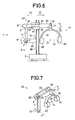
- Figure 6 shows by way of nonlimiting example, a second version of the radiology stand 1 according to the invention.
- the stand 1 comprises a column 80.
- the column 80 is vertical, and it carries a support arm 81 itself carrying the connecting rod 4 already mentioned.
- the connecting rod 4 is fixed by its end 5 to the support arm 81, so as to be free to rotate relative to the latter about the first axis of rotation 7.
- the second end 8 of the connecting rod 4 is fixed to one end 83 of a fourth arm 84, the second end 85 of which carries the foot 27 of the stirrup 24.
- the stirrup 24 has a first and a second branch 28, 29 which respectively support the source and the receiver of x-radiation. 25,26, and the axis 30 of the image chain passes through the isocentre point IC.
- the second end 8 of the connecting rod 4 and the first end 83 of the fourth arm 84 are assembled to each other so that they can be articulated around a fifth axis of rotation 87 perpendicular to the plane of the figure.
- the foot 27 of the stirrup 24 is fixed to the second end 85 of the fourth arm 84, so that it can rotate around the third axis of rotation 33 and, as in the previous example, the radiology stand is arranged so that the foot 27 and more precisely the third axis of rotation 33 is capable of circular movement in a circle whose center is the isocenter IC.
- the radiology stand comprises, on the one hand a second carriage 89, movable along the column 80, and on the other hand comprises a second sheath 90 mounted on the carriage 89 and in which the fourth arm 84 is engaged.
- the fourth arm 84 is thus carried by the second sleeve 90 in which it can slide transversely relative to the column 80, in one or other of the directions shown by the arrows 91.92.
- the support arm and the fourth arm 81, 84 are parallel and that, on the other hand, are also parallel, the connecting rod 4 and the length L of the foot 27; so that these parallel elements two by two represent a parallelogram and, by maintaining the support arm 81 and by deforming the parallelogram, the rotation of the foot 27 is obtained around the isocenter IC.
- the rotation of the foot 27 around the isocentre IC must be accompanied by an orientation of the stirrup 24, so that the long length L of the foot 27 is always substantially parallel to the connecting rod 4; this being obtained using the orientation device 50 (not visible in Figure 6) which, in this version of the invention is particularly simple.
- FIG. 7 shows schematically and by way of nonlimiting example, an embodiment of the device 50 used to orient the stirrup 24 within the framework of the second version of the invention shown in FIG. 6.
- the second end 8 of the connecting rod 4 carries a first wheel 97 and the weight 27 carries a second wheel 98.
- the two wheels are linked together by a notched belt 99 for example, which, between the two wheels 97, 98 is parallel to the fourth arm 84 (shown in Figure 6).
- a rotation of the connecting rod 4 around the first axis of rotation 7, in the direction for example shown by the first arrow 10, causes a movement of the belt 99 which causes rotation of the foot 27 around the third axis of rotation 33; the rotational movements of the connecting rod 4 and of the foot 27 having the same direction and the same amplitude, so that the length L of the foot 27 remains parallel to the connecting rod 4.
- FIG. 8 shows by way of nonlimiting example, a third version of the radiology stand 1 according to the invention.
- the connecting rod 4 is carried by the base 2 to which it is fixed by its end 5, so as to be free to rotate about the first axis of rotation 7.
- the second end 8 of the connecting rod 4 can thus describe a circular movement around the first axis of rotation 7, as in the previous examples; this circular movement is transmitted to the foot 27 of the stirrup 24 in the same way as in the second version described with reference to FIG. 6, that is to say using the fourth arm 84.
- the second end 8 of the connecting rod 4 is fixed to one end 83 of the fourth arm 84, the second end 85 of which carries the foot 27 of the stirrup 24.
- FIG. 9 is a perspective view which shows, by way of nonlimiting example, both an embodiment of the device 50 used to orient the stirrup 24 within the framework of the third version of the invention shown in FIG. 8 , and an embodiment of a device 110 serving to keep the orientation of the fourth arm 84 constant.
- the first orientation device 50 is of the same type as that described with reference to FIG. 7.
- the first connecting rod 4 is fixed by its first end 5 to the base 2 so as to be free to rotate about the first axis of rotation 7.
- the second end 8 of the connecting rod 4 carries the first wheel 97 and the foot 27 of the caliper 24 (partially shown) carries the second wheel 98.
- the two wheels are linked together by the belt 99.
- a rotation of the connecting rod 4 around the first axis of rotation 7, in the direction for example shown by the first arrow 10 causes a movement of the belt 99 which causes rotation of the foot 27 around the third axis 33 and causes the appropriate orientation of the caliper 24.
- the second orientation device 110 intended for maintain a constant orientation to the second arm 84, is produced using a third and a fourth pulley 115,116 connected to each other by a second belt 117.
- the third and fourth pulleys 115,116 are mounted respectively on the base 2 and at the first end 83 of the fourth arm 84, so that the second belt 117 is stretched between these two pulleys 115, 116 parallel to the first connecting rod 4.
- a rotation of the first connecting rod 4 around the first axis of rotation 7, in the direction of the first arrow 10, causes a displacement of the second belt 117, which itself causes a movement of rotation of the fourth arm 84, relative to the first connecting rod 4, around the fifth axis of rotation 87 along which the connecting rod and the fourth arm 84 are assembled.
- This rotary movement of the fourth arm 84 is carried out in a direction represented by an arrow 120, this direction of rotation being suitable for keep its orientation on the fourth arm 4 despite the movement of the connecting rod 4.
Landscapes
- Engineering & Computer Science (AREA)
- General Engineering & Computer Science (AREA)
- Mechanical Engineering (AREA)
- Health & Medical Sciences (AREA)
- Life Sciences & Earth Sciences (AREA)
- Medical Informatics (AREA)
- Optics & Photonics (AREA)
- Biomedical Technology (AREA)
- Biophysics (AREA)
- Nuclear Medicine, Radiotherapy & Molecular Imaging (AREA)
- Physics & Mathematics (AREA)
- Pathology (AREA)
- Radiology & Medical Imaging (AREA)
- High Energy & Nuclear Physics (AREA)
- Heart & Thoracic Surgery (AREA)
- Molecular Biology (AREA)
- Surgery (AREA)
- Animal Behavior & Ethology (AREA)
- General Health & Medical Sciences (AREA)
- Public Health (AREA)
- Veterinary Medicine (AREA)
- Apparatus For Radiation Diagnosis (AREA)
Abstract
L'invention concerne un statif de radiologie, permettant des mouvements isocentriques et destiné notamment au radiodagnostic. Le statif (1) comporte un socle (2) supportant un étrier (24) ayant un premier et un second bras (28,29) portant respectivement une source et un récepteur (25,26) de rayons X. Selon une caractéristique de l'invention, l'étrier (24) comporte un pied (27) par lequel il est supporté par le socle (2), par l'intermédiaire de moyens (4,11,89,90) pour déplacer le pied (27) en un mouvement circulaire ayant pour centre un point isocentre (IC).The invention relates to a radiology stand, allowing isocentric movements and intended in particular for radiodagnosis. The stand (1) comprises a base (2) supporting a stirrup (24) having a first and a second arm (28,29) respectively carrying a source and a receiver (25,26) of X-rays. According to a characteristic of the invention, the stirrup (24) comprises a foot (27) by which it is supported by the base (2), by means (4,11,89,90) to move the foot (27) in a circular movement having for center an isocenter point (IC).
Description
L'invention concerne un statif de radiologie, destiné notamment au radiodiagnostic et permettant une exploration ou examen isocentrique d'un patient avec des incidences multiples.The invention relates to a radiology stand, intended in particular for radiodiagnosis and allowing an isocentric exploration or examination of a patient with multiple incidences.
L'examen radiologique d'un patient s'effectue à l'aide d'une chaine image qui, généralement, est constituée essentiellement d'une source de rayons X, d'un colimateur, d'une grille anti-diffusante et d'un récepteur d'image qui sont portés par le statif et liés rigidement entre eux; la source de rayons x et le collimateur sont d'un même coté par rapport au patient à examiner, et la grille anti-diffusante et le récepteur d'image sont du côté opposé. Une droite passant par le centre de la source de rayonnement x et le centre du récepteur d'image représente l'axe du rayonnement x ou axe de la chaine image qui, dans le cas d'un examen ou exploration isocentrique passe toujours en un même point d'une zone à analyser, quelle que soit l'orientation de cet axe, ce point constituant l'isocentre ; le mouvement que permet de faire varier l'orientation de l'axe de la chaine image en gardant une position fixe par rapport à l'isocentre étant appelé mouvement isocentrique.The radiological examination of a patient is carried out using an image chain which, generally, consists essentially of a source of X-rays, a collimator, an anti-diffusing grid and an image receptor which are carried by the stand and rigidly linked together; the x-ray source and the collimator are on the same side with respect to the patient to be examined, and the anti-scattering grid and the image receptor are on the opposite side. A straight line passing through the center of the x-ray source and the center of the image receptor represents the x-ray axis or axis of the image chain which, in the case of an isocentric examination or exploration always passes through the same point of an area to be analyzed, whatever the orientation of this axis, this point constituting the isocentre; the movement that makes it possible to vary the orientation of the axis of the image chain while keeping a fixed position relative to the isocenter being called isocentric movement.
Les statifs qui permettent de réaliser un mouvement isocentrique comportent, généralement, un arceau ouvert dont une extrémité porte une source de rayons x, et l'autre extrémité porte un récepteur d'image. L'axe de la chaine image constitué entre le récepteur d'image et la source de rayons x passe par l'isocentre, lequel isocentre constitue le centre de l'arceau ou est sur un même axe que le centre de l'arceau de sorte qu'un mouvement isocentrique est réalisé de faisant tourner l'arceau sur lui-même dans son plan, autour de son centre, en faisant coulisser l'arceau dans un fourreau en forme d'arc de cercle par exemple.The stands that allow an isocentric movement generally include an open arch, one end of which carries an x-ray source, and the other end carries an image receptor. The axis of the image chain formed between the image receptor and the x-ray source passes through the isocenter, which isocenter constitutes the center of the arch or is on the same axis as the center of the arch so that an isocentric movement is made by rotating the arch on itself in its plane, around its center, by sliding the arch in a sheath in the shape of an arc of a circle for example.
Un agencement semblable est utilisé aussi bien dans le cas de systèmes radiologiques lourds et importants où les mouvements de l'arceau sont motorisés, que dans le cas de petits systèmes radiologiques, tels que mobiles chirurgicaux ou mammographes par exemple, ou la chaine image n'est pas d'une masse trop élevée, de sorte qu'il n'est pas nécessaire que les mouvements de l'arceau soient motorisés ; ces mouvement pouvant être obtenus par simple action manuelle de l'opérateur.A similar arrangement is used both in the case of heavy and large radiological systems where the movements of the arch are motorized, as in the case of small radiological systems, such as surgical mobiles or mammographs for example, or the image chain does not is not of too high a mass, so that the movements of the roll bar need not be motorized; these movements can be obtained by simple manual action of the operator.
On note en outre que ces différents statifs de radiologie permettent en outre un autre mouvement isocentrique qui consiste en une rotation du plan de l'arceau autour d'un second axe de rotation perpendiculaire au premier, et passant également par l'isocentre.It is further noted that these different radiology stands further allow another isocentric movement which consists of a rotation of the plane of the arch around a second axis of rotation perpendicular to the first, and also passing through the isocenter.
L'un des défauts d'un tel agencement réside dans le fait que, quand l'axe de la chaine image est parallèle à ce second axe, on n'obtient aucune modification de son angle d'incidence à l'aide du second mouvement isocentrique, c'est-à-dire en réalisant une rotation du plan de l'arceau autour du second axe de rotation.One of the shortcomings of such an arrangement lies in the fact that, when the axis of the image chain is parallel to this second axis, no modification of its angle of incidence is obtained using the second movement. isocentric, that is to say by carrying out a rotation of the plane of the arch around the second axis of rotation.
Un autre inconvénient de cet agencement, particulièrement pour les systèmes plus petits non motorisés tels que les mobiles chirurgicaux par exemple, est que les mouvements de l'arceau par simple action manuelle de l'opérateur ne peuvent être obtenus que par un rééquilibrage du système, c'est-à-dire en plaçant des contrepoids à l'extérieur du système, ce qui les rend particulièrement encombrants. On peut noter, pour souligner ce problème, que dans certains de ces petits systèmes dont l'arceau est déplacé sous une action manuelle, la source de rayonnements x et le récepteur d'image sont portés chacun à une extrémité opposée de l'arceau, à des positions très extérieures de ce dernier, c'est-à dire telles que l'axe de la chaine image n'est plus sur un diamètre de l'arceau. Ceci apporte une solution au problème de l'équilibrage, mais présent l'inconvénient d'exiger un mouvement supplémentaire de translation, à chaque nouvelle incidence obtenue par la rotation de l'arceau, pour que l'axe de la chaine image passe par l'isocentre.Another drawback of this arrangement, particularly for smaller non-motorized systems such as surgical mobiles for example, is that the movements of the arch by simple manual action of the operator can only be obtained by rebalancing the system, that is to say by placing counterweights outside the system, which makes them particularly bulky. To underline this problem, it can be noted that in some of these small systems whose hoop is moved under manual action, the x-ray source and the image receiver are each brought to an opposite end of the hoop, at very external positions of the latter, that is to say such that the axis of the image chain is no longer on a diameter of the arch. This provides a solution to the problem of balancing, but has the drawback of requiring an additional translational movement, at each new incidence obtained by the rotation of the arch, so that the axis of the image chain passes through the isocenter.
Il est à observer aussi qu'un autre inconvénient de ces statifs isocentriques, réside en ce qu'il est nécessaire de leur ajouter des moyens importants et encombrants pour substituer l'un à l'autre la source et le récepteur de rayonnements x, par un mouvement isocentrique, tout en conservant une même orientation de l'axe de la chaine image.It should also be observed that another drawback of these isocentric stands is that it is necessary to add significant and bulky means to them to substitute the source and the receiver of x-rays for one another, by an isocentric movement, while retaining the same orientation of the axis of the image chain.
La présente invention concerne un statif de radiologie, permettant des mouvements isocentriques et qui ne présente pas les inconvénients ci-dessus cités. Selon l'invention, un statif de radiologie comportant, un socle, un étrier ayant deux bras, le premier et le second bras portant respectivement une source et un récepteur de rayons x, la source et le récepteur de rayons x définissant entre eux un axe de chaine image passant par un isocentre, et caractérisé en ce que l'étrier comporte un pied, et en ce que le pied est porté par le socle par l'intermédiaire de moyens pour déplacer le pied dans un mouvement circulaire ayant l'isocentre pour centre. L'invention sera mieux comprise grace à la description qui suit faite à titre d'exemple non limitatif et aux sept figures annexées, parmi lesquelles:
- - les figures 1 à 3 montrent de manière schématique une première version d'un statif de radiologie conforme à l'invention ;
- - la figure 4 montre schématiquement un dispositif d'orientation d'un étrier montré aux figures 1 à 3 ;
- - la figure 5 montre schématiquement un dispositif permettant de réaliser un déplacement relatif en translation entre deux bras destinés à porter l'étrier dans la première version de l'invention ;
- - la figure 6 montre schématiquement une seconde version d'un statif de radiologie conforme à l'invention ;
- - la figure 7 montre schématiquement un second dispositif d'orientation de l'étrier ;
- - la figure 8 montre schématiquement une troisième version d'un statif selon l'invention ;
- - la figure 9 montre schématiquement un dispositif pour conserver une orientation constante à un bras montré à la figure 8.
- - Figures 1 to 3 show schematically a first version of a radiology stand according to the invention;
- - Figure 4 schematically shows a device for orienting a stirrup shown in Figures 1 to 3;
- - Figure 5 shows schematically a device for carrying out a relative movement in translation between two arms intended to carry the stirrup in the first version of the invention;
- - Figure 6 schematically shows a second version of a radiology stand according to the invention;
- - Figure 7 schematically shows a second stirrup orientation device;
- - Figure 8 schematically shows a third version of a stand according to the invention;
- FIG. 9 schematically shows a device for maintaining a constant orientation with an arm shown in FIG. 8.
La figure 1 représente un statif de radiologie 1 conforme à une première version de l'invention qui met en oeuvre un principe d'homothétie.FIG. 1 represents a
Le statif de radiologie 1 comporte un socle 2. Dans l'exemple non limitatif décrit, le socle 2 est monté sur un chariot 3. Une bielle 4 est montée sur le socle 2 par une extrémité 5 de la bielle 4 de sorte que la bielle 4 soit libre en rotation par rapport au socle 2, autour d'un axe de rotation 7 (perpendiculaire au plan de la figure) selon lequel l'extrémité 5 est fixée au socle 2. La seconde extrémité 8 de la bielle 4 peut ainsi décrire, autour de l'axe de rotation 7, un mouvement circulaire dans l'un au l'autre des sens représentés par une première et une seconde flèches 10, 12.The
La seconde extrémité 8 de la bielle 4 est fixée à une colonne télescopique 11. Dans l'exemple non limitatif décrit la colonne télescopique 11 est formée par deux bras 13,14 que peuvent être déplacés l'un par rapport à l'autre en translation, le long d'un axe longitudinal 15 de la colonne télescopique 11. Le socle 2 comporte un fourreau 16 dans lequel est engagé et peut coulisser le premier bras 13 de la colonne télescopique 11. La seconde extrémité 8 de la bielle 4 est fixée au premier bras 13, libre en rotation par rapport à ce dernier, de manière à permettre à la fois : le mouvement circulaire de la bielle 4 autour de l'axe de rotation 7 ; et un mouvement circulaire du premier bras 13 autour d'un second axe de rotation 18 (perpendiculaire au plan de la figure), passant sensiblement par le centre du fourreau 16 ; ce mouvement circulaire du premier bras 13 autour du second axe de rotation 18 étant combiné avec un déplacement dans le fourreau 16 du premier bras 13, déplacement qui s'effectue dans l'un ou l'autre des sens montré par une troisième et une quatrième flèches 20,21 (par rapport à l'axe longitudinal 15). Les mouvements accomplis par le premier bras 13 sont également accomplis par le second bras 14 qui, en outre, est mobile par rapport au premier bras 13 le long de l'axe longitudinal 15, et dans un même sens 20, 21 que le premier bras 13.The
Une extrêmité 23 du second bras 14, opposée au premier bras 13, porte un étrier 24 qui lui-même porte une source et un récepteur 25, 26 de rayonnements X ; la source et le récepteur 25, 26 étant situé de part et d'autre d'un patient 6 à examiner. Dans l'exemple non limitatif décrit, l'étrier 24 a la forme d'un diapason ayant un pied 27 et deux branches 28, 29 dont la première 28 porte la source 25, et la seconde 29 porte le récepteur 26. La source et le récepteur de rayonnements x 25,26 définissent entre eux, de manière classique, un axe 30 de chaine image. L'axe de chaine image 30 passe par un point IC qui constitue l'isocentre.One
Le pied 27 est fixé à l'extrémité 23 du second bras 14 de manière à être libre en rotation par rapport à ce dernier ou, plus précisément par rapport à un troisième axe de rotation 33, perpendiculaire au plan contenant les deux branches 28,29 et au plan de la figure.The
Dans l'exemple non limitatif décrit, le pied 27 a une longueur L entre l'extrémité 23 du second bras 14 et les deux branches 28,29, et cette longueur L est disposée sensiblement selon un axe 35 constituant un quatrième axe de rotation 35 passant par l'isocentre 31. En effet, dans l'exemple non limitatif décrit, le pied 27 de l'étrier 24 comporte une première et une seconde partie 36, 37 liées entre elles par des moyens de roulement classique (non représentés), de sorte que la seconde partie 37 attachée aux deux branches 28,29 puisse tourner autour de quatrième axe de rotation 33, par rapport à la première partie 36 qui est attachée à l'extrémité 23 du second bras 14.In the nonlimiting example described, the
Dans cette configuration, le mouvement circulaire de la seconde extrémité 8 de la bielle 4, autour du premier axe de rotation 7, est transformé en un mouvement circulaire du pied 27 autour d'un centre constitué par l'isocentre IC.In this configuration, the circular movement of the
Le statif radiologique 1 comporte d'autre part, un dispositif (non représenté sur la figure 1) pour orienter l'étrier 24 en fonction de l'orientation de la bielle 4, c'est-à-dire de sorte que, d'une part, le point de fixation du pied 27 sur le second bras 14 (point de fixation qui est représenté par le troisième axe de rotation 3), et d'autre part l'isocentre IC se déduisent respectivement de l'extrémité 8 de la bielle 4 ou plus précisement d'un point de fixation 60 de cette dernière sur le premier bras 13, et du premier axe de rotation 7. Dans l'exemple de cette première version de l'invention, ceci est obtenu par une homothétie dont le centre est le second axe de rotation 18, le rapport d'homothétie étant par exemple de 2.The
La figure 1 représente le statif 1 dans une première position P1 de la bielle 4, la bielle 4 étant alors levée, la position P1 étant confondue avec un second axe longitudinal 45 de la bielle 4. Dans cette première position P1 de la bielle 4, la colonne télescopique 11 est à un position extrême de sa course, c'est-à-dire qu'une extrémité 46 du premier bras 13 est sensiblement au niveau du fourreau 16. D'autre part, l'étrier 24 est orienté pour que l'axe de chaine image 30 et la bielle 4 conservent de mêmes orientations relatives, de sorte que l'axe 30 de chaine image passe toujours par l'isocentre IC ; la bielle 4 étant perpendiculaire à l'axe de la chaine image 30, dans l'exemple non limitatif décrit.FIG. 1 represents the
La figure 2 montre le statif 1 conforme à la première version de l'invention, dans une seconde position P2 sensiblement horizontale de la bielle 4, après un mouvement circulaire de cette dernière accompli autour du premier axe de rotation 7 dans le sens de la première flèche 10, selon un angle α un peu supérieur à 90°. Dans l'exemple non limitatif décrit, la bielle 4 n'est pas visible sur le figure 2 du fait qu'elle est montée dans un plan plus profond que le plan de la colonne télescopique 11, par rapport au plan de la figure, et se trouve masquée par la colonne télescopique 11 qui est également horizontale, et les deux axes longitudinaux 15,45 aparaissent confondus. La colonne télescopique 11 est alors engagée au maximum dans le fourreau 16, c'est-à-dire que l'extrémité 46 du premier bras 13 dépasse du fourreau 16 d'une seconde longueur L2 maximum. L'axe 30 de la chaine image passe toujours par l'isocentre IC, mais son orientation qui est maintenant verticale a été modifiée d'une même quantité que l'orientation de la bielle 4.FIG. 2 shows the
La figure 3 montre le statif 1 de la première version pour une troisième position P3 de la bielle 4, obtenue en poursuivant le mouvement circulaire de cette dernière dans le sens de la flèche 10 ; la colonne télescopique 11 étant à nouveau à une position extrême de sa course, c'est-à-dire que l'extrémité 46 du premier bras 13 est revenu au niveau du fourreau 16. entre la première position P1 correspondant à la situation de la figure 1, et la troisième position P3 correspondant à la situation de la figure 3, l'orientation de la bielle 4 a été modifiée d'un angle α 2 plus grand que 180°, et l'orientation de l'axe 30 de chaine image a été modifié dans le même sens et d'une même quantité. Ceci illustre un des avantages de l'invention qui est de pouvoir remplacer l'un par l'autre la source et la récepteur de rayonnements x 25,26, une rotation de 180° de la bielle 4 étant suffisant à cet effet. On peut noter d'autre part que pour toutes les positions possibles entre les position P1 et P3, l'orientation de l'axe 30 de chaîne images peut être modifiée par une rotation des deux branches 28,29 autour du quatrième axe de rotation 35.Figure 3 shows the
La figure 4, montre de manière schématique un dispositif 50 pour réaliser l'orientation de l'étrier 24. Dans l'exemple non limitatif décrit, le dispositif d'orientation 50 comporte un premier et un second engrenage 51,52 montés respectivement à la seconde extrémité 8 de la bielle 4 et à l'extrémité du pied 27, comme il est représenté sur la figure 4. Le premier engrenage 51 comporte un premier et un second pignon conique 53, 54. Le premier pignon 53 est monté à l'extrémité 8 de la bielle 4 et le second pignon 54 est monté sur un axe support 64 lié au second bras 14 (non représenté sur la figure 4). Le second pignon 54 peut coulisser sur l'axe support 64 le long de l'axe longitudinal 15 ; l'axe support 64 comportant à cet effet des canelures 61 parallèles à l'axe longitudinal 15. Cette disposition permet le coulissement du second bras 14 par rapport au premier bras 13 tout en maintenant le second pignon 54 en contact avec le premier pignon 53. Le second engrenage 52 est formé d'un troisième pignon cônique 62 monté à l'extrémité de l'axe support 64, et ce troisième pignon 62 est en prise avec un quatrième pignon 63 monté sur le pied 27. Comme il apparaît sur la figure 4, les engrenages 51,52 sont montés de telle sorte que dans les mouvements conjugués ci-dessus décrits du premier et du second bras 13, 14 et de la bielle 4, d'une part le second pignon 54 coulisse le long des canelures 61 et tourne sur le premier pignon 53 autour d'un centre qui correspond à l'axe de fixation 60 (selon lequel la seconde extrémité 8 de la bielle 4 est fixée sur la colonne télescopique 11) ; ce dernier mouvement du second pignon 54 entraînant la rotation de l'axe support 64 sur lui-même comme représenté par la flèche 66. D'autre part, cette dernière rotation de l'axe support 64 entraîne la rotation du troisième pignon 62 qui, lui-même provoque un mouvement de rotation du quatrième pignon 63 et par conséquent du pied 27 autour du troisième axe de rotation 33, comme représenté par la flèche 67 ; de sorte que la longueur L du pied 27 et le cinquième axe de rotation 35 sont toujours sensiblement parallèles à la bielle 4.FIG. 4 schematically shows a
La figure 5 montre schématiquement, à titre d'exemple non limitatif, comment sont liés l'un à l'autre, le premier et le second bras 13,14 pour obtenir leur mouvement relatif et constituer la colonne télescopique 11. Le premier bras 13 porte une première et une seconde poulie 70,71 qui sont disposées le long de l'axe longitudinal 15 et qui sont montées libres en rotation par rapport au premier arbre 13. Les deux poulies 70,71 sont reliées par une courroie 72 qui est formée autour de ces deux poulies ; de sorte qu'entre les deux poulies 70,71 la courroie 71 a une première et une seconde partie rectilignes 73, 74 , parallèles à l'axe longitudinal 15, et qui sont séparées l'une de l'autre par le diamètre d d'une poulie. La première partie rectiligne 73 est solidaire d'un pion 75 fixé à la seconde barre 14, et la seconde partie rectiligne 74 est solidaire d'un second pion 76 lui-même solidaire d'une partie fixe qui représente le fourreau 16. Dans ces conditions, un mouvement du premier bras 13 par rapport au fourreau 16, dans le sens de la troisième flèche 20 par exemple, provoque un déplacement du second bras 14 par rapport au premier bras 13, et dans un même sens et avec une même amplitude que pour ce dernier, c'est à dire avec une amplitude double par rapport au fourreau 16.FIG. 5 schematically shows, by way of nonlimiting example, how are linked to each other, the first and the
La figure 6 montre à titre d'exemple non limitatif, une seconde version du statif de radiologie 1 conforme à l'invention.Figure 6 shows by way of nonlimiting example, a second version of the radiology stand 1 according to the invention.
Le statif 1 comporte une colonne 80. Dans l'exemple non limitatif de la description, la colonne 80 est verticale, et elle porte un bras support 81 portant lui-même la bielle 4 déjà citée. La bielle 4 est fixée par son extrémité 5 au bras support 81, de manière à être libre en rotation par rapport à ce dernier autour du premier axe de rotation 7. La seconde extrémité 8 de la bielle 4 est fixée à une extrémité 83 d'un quatrième bras 84, dont la seconde extrémité 85 porte le pied 27 de l'étrier 24.The
Comme précédemment expliqué, l'étrier 24 a une première et une seconde branche 28, 29 qui supportent respectivement la source et le récepteur de rayonnement x 25,26, et l'axe 30 de la chaine image passe par le point isocentre IC. La seconde extrémité 8 de la bielle 4 et la première extrémité 83 du quatrième bras 84, sont assemblées l'une à l'autre de manière à pouvoir être articulées autour d'un cinquième axe de rotation 87 perpendiculaire au plan de la figure. Le pied 27 de l'étrier 24 est fixé à la seconde extrémité 85 du quatrième bras 84, de manière à pouvoir tourner autour du troisième axe de rotation 33 et, comme dans l'exemple précédent, le statif de radiologie est agencé pour que le pied 27 et plus précisément le troisième axe de rotation 33 soit capable d'un mouvement circulaire selon un cercle dont le centre est l'isocentre IC.As previously explained, the
A cette fin, dans cette seconde version de l'invention, le statif de radiologie comporte, d'une part un second chariot 89, mobile le long de la colonne 80, et comporte d'autre part un second fourreau 90 monté sur le chariot 89 et dans lequel est engagé le quatrième bras 84. Le quatrième bras 84 est ainsi porté par le second fourreau 90 dans lequel il peut coulisser transversalement par rapport à la colonne 80, dans l'un ou l'autre des sens montrés par les flèches 91,92.To this end, in this second version of the invention, the radiology stand comprises, on the one hand a
On remarque que d'une part, le bras support et le quatrième bras 81,84 sont parallèles et que d'autre part, sont parallèles également, la bielle 4 et la longueur L du pied 27 ; de sorte que ces éléments parallèles deux à deux représentent un parallélogramme et, qu'en maintenant fixe le bras support 81 et en déformant le parallèlogramme on obtient la rotation du pied 27 autour de l'isocentre IC.Note that on the one hand, the support arm and the
En effect, en supposant que le quatrième bras 84 coulisse dans le second fourreau 90, dans le sens de la sixième flèche 91 par exemple, ce mouvement provoque un mouvement de rotation de la bielle 4 autour du premier axe de rotation 7 dans le sens de la première flèche 10, et en même temps un mouvement du chariot 89 le long de la colonne 80 dans le sens d'une huitième flèche 96.In fact, assuming that the
Il est ainsi possible de modifier l'orientation de l'axe 30 de la chaine image d'une manière aussi importante que dans l'exemple précédent et il est à remarquer que cette version de l'invention se prête particulièrement bien à un équilibrage des différents mouvements.It is thus possible to modify the orientation of
Bien entendu la rotation du pied 27 autour de l'isocentre IC doit être accompagnée d'une orientation de l'étrier 24, de sorte que la longueur grand L du pied 27 soit toujours sensiblement parallèle à la bielle 4 ; ceci étant obtenu à l'aide du dispositif d'orientation 50 (non visible sur la figure 6) qui, dans cette version de l'invention est particulièrement simple.Of course, the rotation of the
La figure 7 montre de manière schématique et à titre d'exemple non limitatif, une réalisation du dispositif 50 servant à orienter l'étrier 24 dans le cadre de la seconde version de l'invention montrée à la figure 6.FIG. 7 shows schematically and by way of nonlimiting example, an embodiment of the
La seconde extrémité 8 de la bielle 4 porte une première roue 97 et le peid 27 porte une seconde roue 98. Les deux roues sont liées entre elles par une courroie 99 crantée par exemple, qui, entre les deux roues 97, 98 est parallèle au quatrième bras 84 (montré sur la figure 6). Une rotation de la bielle 4 autour du premier axe de rotation 7, dans le sens par exemple montré par la première flèche 10, entraîne un déplacement de la courroie 99 qui provoque une rotation du pied 27 autour du troisième axe de rotation 33 ; les mouvement de rotation de la bielle 4 et du pied 27 ayant un même sens et une même amplitude, de sort que la longueur L du pied 27 reste parallèle à la bielle 4.The
La figure 8 montre à titre d'exemple non limitatif, une troisième version du statif de radiologie 1 selon l'invention.FIG. 8 shows by way of nonlimiting example, a third version of the radiology stand 1 according to the invention.
La bielle 4 est portée par le socle 2 auquel elle est fixée par son extrémité 5, de manière à être libre en rotation autour de premier axe de rotation 7. La seconde extrémité 8 de la bielle 4 peut ainsi décrire un mouvement circulaire autour du premier axe de rotation 7, comme dans les exemples précèdents; ce mouvement circulaire est transmis au pied 27 de l'étrier 24 d'une même manière que dans la seconde version décrite en réfèrence à la figure 6, c'est à dire à l'aide du quatrième bras 84.The connecting
A cette effet, la seconde extrémité 8 de la bielle 4 est fixée à une extrémité 83 du quatrième bras 84, dont la seconde extrémité 85 porte le pied 27 de l'étrier 24.To this end, the
A la condition d'orienter l'étrier 24, et à la condition de maintenir constante l'orientation du quatrième bras 84, par rapport au socle 2 par exemple (orientation horizontale dans l'exemple non limitatif décrit), un mouvement circulaire de la première bielle 4 autour du premier axe de rotation 7 dans le sens de la première flêche 10 par exemple, engendre un mouvement circulaire de l'étrier 24 selon un cercle ayant pour centre l'isocentre IC. Il est ainsi possible de modifier l'orientation de l'axe 30 de la chaine image d'une manière aussi importante que dans les exemples précèdents.On the condition of orienting the
La figure 9 est une vue en perspective qui montre, à titre d'exemple non limitatif, à la fois une réalisation du dispositif 50 servant à orienter l'étrier 24 dans le cadre de la troisième version de l'invention montré à la figure 8, et une réalisation d'un dispositif 110 servant à maintenir constante l'orientation du quatrième bras 84.FIG. 9 is a perspective view which shows, by way of nonlimiting example, both an embodiment of the
Le premier dispositif d'orientation 50 est d'un même type que celui décrit en réfèrence à la figure 7. La première bielle 4 est fixée par sa première extrémité 5 au socle 2 de manière à être libre en rotation autour du premier axe de rotation 7. La seconde extrémité 8 de la bielle 4 porte la première roue 97 et le pied 27 de l'étrier 24 (partiellement représenté) porte la seconde roue 98. Les deux roues sont liées entre elles par la courroie 99. Une rotation de la bielle 4 autour du premier axe de rotation 7, dans le sens par exemple montré par la première flêche 10, entraine un déplacement de la courroie 99 qui provoque une rotation du pied 27 autour du troisième axe 33 et entraine l'orientation appropriée de l'étrier 24.The
Le second dispositif d'orientation 110 déstiné à conserver une orientation constante au second bras 84, est réalisé à l'aide d'une troisième et d'une quatrième poulie 115,116 reliées entre elles par une seconde courroie 117. La troisième et quatrième poulies 115,116 sont montées respectivement sur le socle 2 et à la première extrémité 83 du quatrième bras 84, de sorte que la seconde courroie 117 est tendue entre ces deux poulies 115,116 parallèlement à la première bielle 4.The
Une rotation de la première bielle 4 autour du premier axe de rotation 7, dans le sens de la première flêche 10, entraine un déplacement de la seconde courroie 117, qui elle-même entraine un mouvement de rotation de quatrième bras 84, par rapport à la première bielle 4, autour du cinquième axe de rotation 87 selon lequel sont assemblés la bielle et le quatrième bras 84. Ce mouvement de rotation du quatrième bras 84 est effectué dans un sens représenté par une flêche 120, ce sens de rotation étant approprié à conserver son orientation au quatrième bras 4 malgrès le mouvement de la bielle 4.A rotation of the first connecting
Claims (7)
Applications Claiming Priority (2)
| Application Number | Priority Date | Filing Date | Title |
|---|---|---|---|
| FR8718300 | 1987-12-29 | ||
| FR8718300A FR2625094B1 (en) | 1987-12-29 | 1987-12-29 | ISOCENTRIC RADIOLOGY STAND |
Publications (1)
| Publication Number | Publication Date |
|---|---|
| EP0323327A1 true EP0323327A1 (en) | 1989-07-05 |
Family
ID=9358394
Family Applications (1)
| Application Number | Title | Priority Date | Filing Date |
|---|---|---|---|
| EP88403292A Ceased EP0323327A1 (en) | 1987-12-29 | 1988-12-22 | Support for isocentric explorations |
Country Status (4)
| Country | Link |
|---|---|
| US (1) | US4964151A (en) |
| EP (1) | EP0323327A1 (en) |
| JP (1) | JPH01214342A (en) |
| FR (1) | FR2625094B1 (en) |
Cited By (2)
| Publication number | Priority date | Publication date | Assignee | Title |
|---|---|---|---|---|
| FR2818116A1 (en) * | 2000-12-19 | 2002-06-21 | Ge Med Sys Global Tech Co Llc | Mammography device has a frame arrangement for support of the radiation source and imaging equipment that allows the patient to be easily examined standing up, sitting down, bent forwards or lying down |
| EP3461410A1 (en) * | 2017-09-29 | 2019-04-03 | Koninklijke Philips N.V. | Kinematical joints for x-ray systems |
Families Citing this family (16)
| Publication number | Priority date | Publication date | Assignee | Title |
|---|---|---|---|---|
| JPH03116810U (en) * | 1990-03-16 | 1991-12-03 | ||
| FR2679124B1 (en) * | 1991-07-19 | 1993-11-19 | General Electric Cgr Sa | RADIOLOGICAL MOBILE. |
| US5388142A (en) * | 1991-11-27 | 1995-02-07 | X-Cel X-Ray Corporation | Portable radiographic device |
| US5283823A (en) * | 1991-11-27 | 1994-02-01 | X-Cel X-Ray Corporation | Portable radiographic device |
| DE19532965C2 (en) * | 1995-09-07 | 1998-07-16 | Heimann Systems Gmbh & Co | X-ray inspection system for large-volume goods |
| US7578618B2 (en) * | 2005-09-09 | 2009-08-25 | Koninklijke Philips Electronics N.V. | X-ray examination device |
| DE102006011234A1 (en) * | 2006-03-10 | 2007-09-13 | Siemens Ag | X-ray recording device with an X-ray detector and an X-ray source |
| US7587027B2 (en) | 2006-12-23 | 2009-09-08 | X-Cel X-Ray | Method and apparatus for determining and displaying x-ray radiation by a radiographic device |
| JP5574589B2 (en) * | 2008-09-01 | 2014-08-20 | キヤノン株式会社 | X-ray equipment |
| DE102011006505B4 (en) * | 2011-03-31 | 2014-07-31 | Siemens Aktiengesellschaft | Mobile C-arm X-ray machine with anti-tipper device |
| CN103505234B (en) * | 2012-06-29 | 2016-09-14 | Ge医疗系统环球技术有限公司 | The transverse arm of a kind of X-ray machine and corresponding X-ray machine |
| JP6386959B2 (en) * | 2015-03-30 | 2018-09-05 | 日本発條株式会社 | lift device |
| CN104897702B (en) * | 2015-06-24 | 2017-08-08 | 中国石油天然气第一建设有限公司 | A kind of small diameter tube banjo fixing butt jointing gamma ray detection special tooling |
| CN104950003B (en) * | 2015-06-24 | 2017-08-15 | 中国石油天然气第一建设有限公司 | A kind of gamma ray detection method of small diameter tube banjo fixing butt jointing |
| CN107714065A (en) | 2017-09-29 | 2018-02-23 | 上海联影医疗科技有限公司 | X-ray imaging equipment |
| GB2623374A (en) * | 2022-10-14 | 2024-04-17 | Xstrahl Ltd | Improvements in or relating to medical device apparatus |
Citations (2)
| Publication number | Priority date | Publication date | Assignee | Title |
|---|---|---|---|---|
| CH426094A (en) * | 1964-10-15 | 1966-12-15 | Philips Nv | Column stand to support a movable beam, which is provided with an X-ray tube and a radiation interceptor |
| EP0160749A1 (en) * | 1984-04-09 | 1985-11-13 | Siemens Aktiengesellschaft | X-ray examination apparatus |
Family Cites Families (3)
| Publication number | Priority date | Publication date | Assignee | Title |
|---|---|---|---|---|
| JPS509637B1 (en) * | 1970-09-17 | 1975-04-14 | ||
| US3892967A (en) * | 1973-12-10 | 1975-07-01 | Measurex Corp | Apparatus for radiological examination of a subject through a solid angle |
| DE2745883A1 (en) * | 1977-10-12 | 1979-04-19 | Siemens Ag | X-RAY EXAMINER |
-
1987
- 1987-12-29 FR FR8718300A patent/FR2625094B1/en not_active Expired - Fee Related
-
1988
- 1988-12-22 EP EP88403292A patent/EP0323327A1/en not_active Ceased
- 1988-12-28 US US07/291,154 patent/US4964151A/en not_active Expired - Lifetime
-
1989
- 1989-01-04 JP JP64000234A patent/JPH01214342A/en active Pending
Patent Citations (2)
| Publication number | Priority date | Publication date | Assignee | Title |
|---|---|---|---|---|
| CH426094A (en) * | 1964-10-15 | 1966-12-15 | Philips Nv | Column stand to support a movable beam, which is provided with an X-ray tube and a radiation interceptor |
| EP0160749A1 (en) * | 1984-04-09 | 1985-11-13 | Siemens Aktiengesellschaft | X-ray examination apparatus |
Cited By (5)
| Publication number | Priority date | Publication date | Assignee | Title |
|---|---|---|---|---|
| FR2818116A1 (en) * | 2000-12-19 | 2002-06-21 | Ge Med Sys Global Tech Co Llc | Mammography device has a frame arrangement for support of the radiation source and imaging equipment that allows the patient to be easily examined standing up, sitting down, bent forwards or lying down |
| US6848826B2 (en) | 2000-12-19 | 2005-02-01 | Ge Medical Systems Global Technology Company, Llc | Mammography apparatus and method |
| EP3461410A1 (en) * | 2017-09-29 | 2019-04-03 | Koninklijke Philips N.V. | Kinematical joints for x-ray systems |
| WO2019063657A1 (en) * | 2017-09-29 | 2019-04-04 | Koninklijke Philips N.V. | Kinematical joints for x-ray systems |
| US11737716B2 (en) | 2017-09-29 | 2023-08-29 | Koninklijke Philips N.V. | Kinematical joints for x-ray systems |
Also Published As
| Publication number | Publication date |
|---|---|
| FR2625094A1 (en) | 1989-06-30 |
| FR2625094B1 (en) | 1994-02-11 |
| JPH01214342A (en) | 1989-08-28 |
| US4964151A (en) | 1990-10-16 |
Similar Documents
| Publication | Publication Date | Title |
|---|---|---|
| EP0323327A1 (en) | Support for isocentric explorations | |
| EP0069607B1 (en) | Sliding load holder with a telescopic structure and x-ray apparatus provided with such a sliding load holder | |
| FR2632177A1 (en) | STATUS OF ISOCENTRIC RADIOLOGY WITH FOUR AXES OF ROTATION | |
| FR2512768A1 (en) | WHEEL SUSPENSION SYSTEM FOR A MOTORCYCLE COMPRISING A DAMPING MECHANISM BETWEEN A STABLE MEMBER AND AN OSCILLATING MEMBER | |
| FR2487082A1 (en) | ADJUSTING DEVICE FOR THE OPTICAL INSTRUMENT PLATE HOLDER | |
| FR2521055A1 (en) | INDUSTRIAL ROBOT | |
| FR2459054A1 (en) | RADIATION THERAPEUTIC TREATMENT APPARATUS AND RETRACTABLE BEAM STOPPING DEVICE FOR THIS APPARATUS | |
| FR2641722A1 (en) | DEVICE FOR DRIVING A TOOL HOLDER PIN | |
| FR2697204A1 (en) | Angle fold device comprising a balancing system. | |
| CA2070442A1 (en) | Gamma camera having two opposite detectors with independent radial movements | |
| EP0165157A1 (en) | X-ray apparatus affording full access to a patient | |
| CA2070462A1 (en) | Tomographic gamma camera equipped with a steerable detector | |
| EP0122849B1 (en) | Support for isocentric explorations | |
| FR2906266A1 (en) | DEVICE FOR CONTROLLING FLEXIBLE LANCE AND WEAVING INCORPORATING AT LEAST ONE SUCH DEVICE | |
| FR2493948A1 (en) | IMPULSIVE VARIATOR | |
| EP0376807B1 (en) | Patient support table for examinations on scintigraphy apparatuses | |
| FR2545185A1 (en) | Spring leg with constant supporting capacity | |
| EP0067487A1 (en) | X-ray table with variable incidence and variable focus permitting planigraphy | |
| CH638423A5 (en) | GRINDING DEVICE FOR PROFILING GRINDING WHEELS. | |
| FR2632513A1 (en) | RADIOLOGICAL EXAMINATION DEVICE | |
| EP0159947B1 (en) | Guiding mechanism | |
| EP0007339B1 (en) | Apparatus for panoramic radiography | |
| FR2640868A1 (en) | ||
| EP0066497A1 (en) | Support for a multidirectional radiation source | |
| BE377644A (en) |
Legal Events
| Date | Code | Title | Description |
|---|---|---|---|
| PUAI | Public reference made under article 153(3) epc to a published international application that has entered the european phase |
Free format text: ORIGINAL CODE: 0009012 |
|
| AK | Designated contracting states |
Kind code of ref document: A1 Designated state(s): DE ES GB IT NL |
|
| 17P | Request for examination filed |
Effective date: 19890605 |
|
| 17Q | First examination report despatched |
Effective date: 19920220 |
|
| STAA | Information on the status of an ep patent application or granted ep patent |
Free format text: STATUS: THE APPLICATION HAS BEEN REFUSED |
|
| 18R | Application refused |
Effective date: 19930408 |