EP0323089A2 - Extrussionsvorrichtung - Google Patents
Extrussionsvorrichtung Download PDFInfo
- Publication number
- EP0323089A2 EP0323089A2 EP88311969A EP88311969A EP0323089A2 EP 0323089 A2 EP0323089 A2 EP 0323089A2 EP 88311969 A EP88311969 A EP 88311969A EP 88311969 A EP88311969 A EP 88311969A EP 0323089 A2 EP0323089 A2 EP 0323089A2
- Authority
- EP
- European Patent Office
- Prior art keywords
- passage
- range
- angle
- axis
- wall
- Prior art date
- Legal status (The legal status is an assumption and is not a legal conclusion. Google has not performed a legal analysis and makes no representation as to the accuracy of the status listed.)
- Granted
Links
Images
Classifications
-
- B—PERFORMING OPERATIONS; TRANSPORTING
- B29—WORKING OF PLASTICS; WORKING OF SUBSTANCES IN A PLASTIC STATE IN GENERAL
- B29C—SHAPING OR JOINING OF PLASTICS; SHAPING OF MATERIAL IN A PLASTIC STATE, NOT OTHERWISE PROVIDED FOR; AFTER-TREATMENT OF THE SHAPED PRODUCTS, e.g. REPAIRING
- B29C44/00—Shaping by internal pressure generated in the material, e.g. swelling or foaming ; Producing porous or cellular expanded plastics articles
- B29C44/20—Shaping by internal pressure generated in the material, e.g. swelling or foaming ; Producing porous or cellular expanded plastics articles for articles of indefinite length
- B29C44/32—Incorporating or moulding on preformed parts, e.g. linings, inserts or reinforcements
- B29C44/334—Filling the preformed spaces or cavities
-
- B—PERFORMING OPERATIONS; TRANSPORTING
- B29—WORKING OF PLASTICS; WORKING OF SUBSTANCES IN A PLASTIC STATE IN GENERAL
- B29C—SHAPING OR JOINING OF PLASTICS; SHAPING OF MATERIAL IN A PLASTIC STATE, NOT OTHERWISE PROVIDED FOR; AFTER-TREATMENT OF THE SHAPED PRODUCTS, e.g. REPAIRING
- B29C44/00—Shaping by internal pressure generated in the material, e.g. swelling or foaming ; Producing porous or cellular expanded plastics articles
- B29C44/34—Auxiliary operations
- B29C44/36—Feeding the material to be shaped
- B29C44/46—Feeding the material to be shaped into an open space or onto moving surfaces, i.e. to make articles of indefinite length
- B29C44/50—Feeding the material to be shaped into an open space or onto moving surfaces, i.e. to make articles of indefinite length using pressure difference, e.g. by extrusion or by spraying
- B29C44/507—Feeding the material to be shaped into an open space or onto moving surfaces, i.e. to make articles of indefinite length using pressure difference, e.g. by extrusion or by spraying extruding the compound through an annular die
-
- B—PERFORMING OPERATIONS; TRANSPORTING
- B29—WORKING OF PLASTICS; WORKING OF SUBSTANCES IN A PLASTIC STATE IN GENERAL
- B29C—SHAPING OR JOINING OF PLASTICS; SHAPING OF MATERIAL IN A PLASTIC STATE, NOT OTHERWISE PROVIDED FOR; AFTER-TREATMENT OF THE SHAPED PRODUCTS, e.g. REPAIRING
- B29C48/00—Extrusion moulding, i.e. expressing the moulding material through a die or nozzle which imparts the desired form; Apparatus therefor
- B29C48/001—Combinations of extrusion moulding with other shaping operations
- B29C48/0013—Extrusion moulding in several steps, i.e. components merging outside the die
- B29C48/0015—Extrusion moulding in several steps, i.e. components merging outside the die producing hollow articles having components brought in contact outside the extrusion die
-
- B—PERFORMING OPERATIONS; TRANSPORTING
- B29—WORKING OF PLASTICS; WORKING OF SUBSTANCES IN A PLASTIC STATE IN GENERAL
- B29C—SHAPING OR JOINING OF PLASTICS; SHAPING OF MATERIAL IN A PLASTIC STATE, NOT OTHERWISE PROVIDED FOR; AFTER-TREATMENT OF THE SHAPED PRODUCTS, e.g. REPAIRING
- B29C48/00—Extrusion moulding, i.e. expressing the moulding material through a die or nozzle which imparts the desired form; Apparatus therefor
- B29C48/03—Extrusion moulding, i.e. expressing the moulding material through a die or nozzle which imparts the desired form; Apparatus therefor characterised by the shape of the extruded material at extrusion
- B29C48/09—Articles with cross-sections having partially or fully enclosed cavities, e.g. pipes or channels
-
- B—PERFORMING OPERATIONS; TRANSPORTING
- B29—WORKING OF PLASTICS; WORKING OF SUBSTANCES IN A PLASTIC STATE IN GENERAL
- B29C—SHAPING OR JOINING OF PLASTICS; SHAPING OF MATERIAL IN A PLASTIC STATE, NOT OTHERWISE PROVIDED FOR; AFTER-TREATMENT OF THE SHAPED PRODUCTS, e.g. REPAIRING
- B29C48/00—Extrusion moulding, i.e. expressing the moulding material through a die or nozzle which imparts the desired form; Apparatus therefor
- B29C48/16—Articles comprising two or more components, e.g. co-extruded layers
- B29C48/18—Articles comprising two or more components, e.g. co-extruded layers the components being layers
- B29C48/21—Articles comprising two or more components, e.g. co-extruded layers the components being layers the layers being joined at their surfaces
-
- B—PERFORMING OPERATIONS; TRANSPORTING
- B29—WORKING OF PLASTICS; WORKING OF SUBSTANCES IN A PLASTIC STATE IN GENERAL
- B29C—SHAPING OR JOINING OF PLASTICS; SHAPING OF MATERIAL IN A PLASTIC STATE, NOT OTHERWISE PROVIDED FOR; AFTER-TREATMENT OF THE SHAPED PRODUCTS, e.g. REPAIRING
- B29C48/00—Extrusion moulding, i.e. expressing the moulding material through a die or nozzle which imparts the desired form; Apparatus therefor
- B29C48/25—Component parts, details or accessories; Auxiliary operations
- B29C48/30—Extrusion nozzles or dies
- B29C48/32—Extrusion nozzles or dies with annular openings, e.g. for forming tubular articles
- B29C48/34—Cross-head annular extrusion nozzles, i.e. for simultaneously receiving moulding material and the preform to be coated
-
- B—PERFORMING OPERATIONS; TRANSPORTING
- B29—WORKING OF PLASTICS; WORKING OF SUBSTANCES IN A PLASTIC STATE IN GENERAL
- B29C—SHAPING OR JOINING OF PLASTICS; SHAPING OF MATERIAL IN A PLASTIC STATE, NOT OTHERWISE PROVIDED FOR; AFTER-TREATMENT OF THE SHAPED PRODUCTS, e.g. REPAIRING
- B29C48/00—Extrusion moulding, i.e. expressing the moulding material through a die or nozzle which imparts the desired form; Apparatus therefor
- B29C48/25—Component parts, details or accessories; Auxiliary operations
- B29C48/36—Means for plasticising or homogenising the moulding material or forcing it through the nozzle or die
- B29C48/50—Details of extruders
- B29C48/695—Flow dividers, e.g. breaker plates
- B29C48/70—Flow dividers, e.g. breaker plates comprising means for dividing, distributing and recombining melt flows
-
- B—PERFORMING OPERATIONS; TRANSPORTING
- B29—WORKING OF PLASTICS; WORKING OF SUBSTANCES IN A PLASTIC STATE IN GENERAL
- B29C—SHAPING OR JOINING OF PLASTICS; SHAPING OF MATERIAL IN A PLASTIC STATE, NOT OTHERWISE PROVIDED FOR; AFTER-TREATMENT OF THE SHAPED PRODUCTS, e.g. REPAIRING
- B29C48/00—Extrusion moulding, i.e. expressing the moulding material through a die or nozzle which imparts the desired form; Apparatus therefor
- B29C48/03—Extrusion moulding, i.e. expressing the moulding material through a die or nozzle which imparts the desired form; Apparatus therefor characterised by the shape of the extruded material at extrusion
- B29C48/09—Articles with cross-sections having partially or fully enclosed cavities, e.g. pipes or channels
- B29C48/10—Articles with cross-sections having partially or fully enclosed cavities, e.g. pipes or channels flexible, e.g. blown foils
-
- B—PERFORMING OPERATIONS; TRANSPORTING
- B29—WORKING OF PLASTICS; WORKING OF SUBSTANCES IN A PLASTIC STATE IN GENERAL
- B29C—SHAPING OR JOINING OF PLASTICS; SHAPING OF MATERIAL IN A PLASTIC STATE, NOT OTHERWISE PROVIDED FOR; AFTER-TREATMENT OF THE SHAPED PRODUCTS, e.g. REPAIRING
- B29C48/00—Extrusion moulding, i.e. expressing the moulding material through a die or nozzle which imparts the desired form; Apparatus therefor
- B29C48/25—Component parts, details or accessories; Auxiliary operations
- B29C48/30—Extrusion nozzles or dies
- B29C48/32—Extrusion nozzles or dies with annular openings, e.g. for forming tubular articles
- B29C48/335—Multiple annular extrusion nozzles in coaxial arrangement, e.g. for making multi-layered tubular articles
Definitions
- the present invention relates to extrusion apparatus and, more particularly to an extrusion head which is capable of extruding tubular elements in which a relatively thick intermediate layer is sandwiched between inner and outer layers of the same material, at least the intermediate layer being composed of a synthetic resin foam.
- Multilayer extrusion heads have been previously proposed in which two or more layers or walls are extruded in a structure by passing the flow of one synthetic resin material through one passage and causing another synthetic resin material to flow codirectionally with the first flow, around the latter so as to meet it at a point in which the flows join to provide a multilayer structure.
- the flow from an extruder is passed axially and split into two generally annular streams which continue along separate paths until they meet a codirectionally moving stream from a second extruder which is forced into an annular passage between the first two streams.
- the streams meet, they form a triple-wall coextrusion which can be condensed in thickness, if desired, to emerge from the extrusion head as a tubular structure having inner and outer layers which derive from the synthetic resin material of the first extruder, and an intermediate layer sandwiched and bonded to the outer and inner layers, which derives from the second extruder.
- the coextrusion head hereinafter described produces tubular bodies having an inner and outer layer sandwiching between them an intermediate layer of a material different from the inner and outer layers, which operates with greater regularity over longer periods to produce defect-free tubular products with high efficiency.
- the apparatus for the purposes described is easy to assemble and maintain.
- the apparatus has an outer annular passage and a central passage for the outer layer and the inner layer, respectively, so that they originate at a location downstream of the location at which an axial flow of the synthetic resin for the intermediate layer is caused to spread into an annular flow.
- the extrusion head for the foamed intermediate layer communicates with an axial extending passage in which a spider is provided to spread the axial flow of this synthetic resin into an annular axial flow of this synthetic resin into an annular axial stream which meets the axial flows of the synthetic resin introduced at an acute angle to the axis of the apparatus from the other extruder.
- the coextrusion apparatus can thus comprise: a body formed with an intermediate axial passage communicating at one end with a source of a foamable synthetic resin adapted to form an intermediate wall of a triple wall coextrusion; a spider in the intermediate passage formed with a central member extending along the intermediate passage and diverting a flow of the foamable synthetic resin around the spider, the spider having an inner passage with an upstream end coaxial with the intermediate passage and terminating in the intermdiate passage at a downstream end of the central member and the inner passage; means forming in the body an outer passage coaxial with the intermediate and inner passages and extending axially over part of the length of the member aound the intermediate passage, the outer passage having a downstream end and an upstream end; a feed fitting secured to the body and connected to a second source of synthetic resin adapted to form inner and outer walls of the coextrusion, the feed fitting being formed with an inlet channel including an acute angle with an axis of the body and the passages and converging toward the axis in a
- the foam PVC material forming the middle layer of the triple wall pipe undergoes an expansion which is much greater than that of the inner and outer layers of the pipe and requires 50% to 75% of the pipe material.
- the extrusion head In order to insure the proper expansion and bonding of the foam layer with the inner and outer layers, the extrusion head must be formed with restricted flow passages and precision angles for the proper flow and compression of the PVC foam, whereby the PVC foam after leaving the plasticizing extruder and entering the extrusion head in a compressed state is allowed to expand and decompress over a certain length of the flow passage, where the PVC foam is gradually once again compressed over a longer length of the flow passage to the exit, where it enters the die passages flanked by the inner and outer layers and is then expanded to the full pipe diameter.
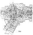
- An extrusion head 1 centered on a horizontal axis 0 is formed with three coaxial flow passages in the downstream die exit area of the head for extruding triple layer pipe in which the intermediate layer is an expanded PVC foam material and the inner and outer layers are rigid PVC material.
- a central passage 2a is formed in an insert 2 of the head 1 for a PVC foam from a plasticizing extruder not shown.
- the passage 2a is confronted with the apex 3′ of a conical head 3 of a mandrel 4 coaxially disposed in the extrusion head 1 and supported therein by the webs of a spider 5.
- the conical head 3 divides the flow of PVC foam into a conical passage 2b, which is expanded in the downstream direction by the divergence of the wall 7a of the conical head and the wall 8a of the extrusion head, the wall 7a forming an angle A2 with the axis 0 of 25° to 42°, and the wall 8a forming an angle A1 with the axis 0 of 32° to 45°, which will allow the PVC foam, which is to form the intermediate layer of the pipe, to expand and decompress.
- the outer conical wall 8a extends outwardly and rearwardly to blend with an annular wall 8b; having a diameter D1 of 19.8 cm to 24.1 cm (7.8" to 9.5") which extends for a length L1 of 0.5 cm to 3.8 cm (.2" to 1.5") to the spider 5 and continues on the other side thereof as annular wall 8c having a diameter D2 of 20.3 cm to 22.9 cm (8" to 9").
- the inner conical wall 7a extends from the apex 3′ outwardly and rearwardly to blend with an annular wall 7b having a diameter d1 15.2 cm to 19 cm (6" to 7.5") which extends for a length of L2 of 0.5 cm to 3 cm (.2" to 1.2") to the spider 5 and contiunues on the other side thereof as annular wall 7c having a diameter d2 of 14 cm to 38.1 cm (5.5" to 7") the inner and outer annular walls 7b, 7c and 8b, 8c forming with the spider an arc segmental passage 2c which can be cylindrical or slightly converging or diverging.
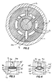
- the annular spider 5, as best seen in Figs. 2-4 is formed with six webs spaced equally apart to withstand a great deal of pressure and support the spider cone 4 and mandrel 2 securely within the head 1.
- Five of the webs 9 are identical and are each formed with a leading knife edge 9′ having beveled flanks 9a′ forming between them an angle A15 of 65° to 75°, and a trailing knife edge 9 ⁇ having beveled flanks 9a ⁇ forming between them an angle A16 of 45° to 56°, each web 9 having a thickness T1 of 2.3 cm to 2.5 cm (.9" to 1") and a flow length L3 measured along the walls 9a′, 9a and 9a ⁇ of 1.5 cm to 3.3 cm (.6" to 1.3").
- the sixth web 10 is designed to allow a flow passage 20c for the PVC material forming the inner layer of the pipe to pass through it and as such, has a leading knife edge 10′ and a trailing knife edge 10 ⁇ having respective beveled flanks 10a′ and 10a ⁇ forming between the same angle of A17 52° to 68° , the web 21 having a thickness T2 of 2.5 cm to 5 cm (1" to 2") and a flow length L4 measured along the walls 10a′, 10a and 10a ⁇ of 3.3 cm to 4.8 cm (1.3" to 1.9").
- All of the spider webs 9 and 10 are designed with the proper leading and trailing edge angles and thicknesses to produce a smooth material separation and gradual bringing together of the foam without causing temperature changes or dragging, which could cause pipe tearing, visible lines or even extra back pressure and material burning.
- each layer of material must have a high but controlled output rate. This is achieved by producing a compression ratio range defined, for instance, by the relationship of the spider outlet cross sectional area and the cross sectional area of the head or die exit 2f, or for the outer pipe layer, the cross sectional area of the annular passage 30c and the cross sectional area of the head exit 30e.
- the spider outlet area is 129 cm2 to 193cm2 (20"2 to 30"2) which produces a compression ratio of 11:1 to 35:1, which is identical to the compression ratio between the annular chamber 30c and outlet 30e.
- the annular passage 2c Downstream of the spider 5, the annular passage 2c becomes a conical passage 2d which narrows in the downstream direction by the convergence of the inner mandrel wall 7d and the outer extrusion head wall 8d, the wall 7d forming an angle A3 with the axis 0 of 15° to 26°, and the wall 8d forming an angle A4 with the axis 0 of 20° to 32°, this convergence again compressing the foam until the proper compression ratio and foam volume is obtained.
- the conical passage 2d becomes a more nearly horizontal conical passage 2e which narrows in the downstream direction by the convergence of the inner mandrel wall 7e and outer extrusion head wall 8e, the wall 7e forming an angle A5 with the axis 0 of 1° to 9°, and the wall 8e forming an angle A6 with the axis 0 of 17° to 30°, the configuration of the four angles A3, A4, and A6 continuously compressing the foam until the proper compresion ratio is obtained, which is reached in the die area where the passages all run horizontal and parallel and define the land length. Again, these angles will prevent turbulence and burning.
- the passage 2f Downstream of the conical passage 2e, the passage 2f becomes cylindrical and enters what is considered the die area or land length, in which the PVC foam layer runs parallel between the inner and outer layers of the pipe.
- the land length for the foam material must be a specific length to allow for proper material plasticizing, stabilizing and controlling of back pressure.
- the proper length is defined as the given cylindrical area corresponding to the die exit diameter.
- the land length L5 of passage 2f is 5.1 cm to 25.4 cm (2" to 10") long.
- the location of the land length is such that its exit point is in proper alignment with the respective exit points of the inner and outer layers.
- the PVC material which is to form the rigid inner and outer layers of the pipe is plasticized in a suitable extruder (not shown) and passed through an inlet 11 into a Y-block 12 centered on an axis 0′ inclined to the axis 0 to feed in the downstream direction at an angle A7 of 55° to 75°.
- a wedge 13 formed in the Y-block divides the incoming flow into two passages 20a and 30a, each forming an angle A8 with the axis 0′ of 20° to 30°, which allows no disturbance in the flow, yet allowing the Y-block 12 to be formed in one piece.
- Each passage 20a and 30a is joined by a respective insert 14 and 15, having a respective passage 20b and 30b, to the body of the extrusion head 1, each insert being designed to separetely control the output rate of their respective pipe layers as required.
- the inserts 14 and 15 also control proper melting conditions and back pressure in the extruder.
- the flow passage 20b Downstream of the insert 14, the flow passage 20b, which carries the pipe's inner layer of PVC material, becomes passage 20c which extends through the spider 5 and the web 10 thereof at an angle A9 of 10° to 18° with the axis 0′.
- the angle A9 is such that the passage 20c passes directly through the centre of the web 10 from the insert 14 to the next mating part, the spider insert 16.
- the mating of the parts 1,5 and 16 requires extremely tight tolerances in the angle alignments during the assembly of the extrusion head.
- the spider insert 16 is designed to allow the proper turning angle conversion from the passage 20c to the central outlet passage 20e without turbulence, burns or back pressure build-up of the PVC material and is formed with an arcuate passage 20d, the central passage 20e maintaining the proper compression and residence time of the material.
- the flow area of the passage 20e must be 3.2 cm2 to 7.7 cm2 (.5"2 to 1.2"2) and have a land length L6 of 30.5 cm to 50.8 cm (12" to 20").
- the passage 20e is also designed so that the exit point is in alignment with the other flow passage's exit points.
- the flow passage 30b Downstream of the insert 15, the flow passage 30b, which carries the pipe's outer layer of PVC material, becomes annular chamber 30c formed in extrusion head 1 and centered on axis 0 and having a back wall 17 inclined to a perpendicular to the axis 0 at an angle A10 of 19° to 27°.
- the annular chamber 30c acts to distribute the flow of PVC material from the tubular passage 30b into an annular flow.
- the passage 30d Downstream of the annular chamber 30c, the passage 30d becomes conical and narrows in the downstream direction by the convergence of the inner wall 18 and the outer wall 19a, the wall 18 forming an angle A11 with the axis 0 of 15° to 26°, and the outer wall 19a forming an angle A12 with the axis 0 of 20° to 35°, this decrease in volume of the passage 30d acting to distribute the output rate evenly throughout the chamber and passage as the material leaves the extrusion head.
- the outer wall along an upper portion 19b and 19c of the passage 30d bends through two more angles, namely angle A13 of wall portion 19b at 17° to 30° to the axis 0, and angle A14 of wall portion 19c at 5° to 16° to the axis 0, leaving the upper wall portion of passage 30e with a land length L7 of 2.54 cm to 12.7 cm (1" to 5") while the lower wall portion 19a continues to the passage 30e at which a land length L8 of 6.35 cm to 17.8 cm (2.5" to 7") is formed.
- each layer has a specified percent of material thickness at this point.
- the outer layer has 15% to 20%
- the inner layer has 18% to 30%
- the intermediate layer has 50% to 75% of the required pipe material.
Landscapes
- Engineering & Computer Science (AREA)
- Mechanical Engineering (AREA)
- Manufacturing & Machinery (AREA)
- Extrusion Moulding Of Plastics Or The Like (AREA)
- Molding Of Porous Articles (AREA)
Priority Applications (1)
| Application Number | Priority Date | Filing Date | Title |
|---|---|---|---|
| DE8817229U DE8817229U1 (de) | 1987-12-31 | 1988-12-16 | Extrusionsvorrichtung |
Applications Claiming Priority (2)
| Application Number | Priority Date | Filing Date | Title |
|---|---|---|---|
| US07/139,958 US4846648A (en) | 1986-11-19 | 1987-12-31 | Triple-wall foam coextrusion apparatus |
| US139958 | 1998-08-25 |
Publications (3)
| Publication Number | Publication Date |
|---|---|
| EP0323089A2 true EP0323089A2 (de) | 1989-07-05 |
| EP0323089A3 EP0323089A3 (en) | 1990-05-09 |
| EP0323089B1 EP0323089B1 (de) | 1994-06-01 |
Family
ID=22489085
Family Applications (1)
| Application Number | Title | Priority Date | Filing Date |
|---|---|---|---|
| EP88311969A Expired - Lifetime EP0323089B1 (de) | 1987-12-31 | 1988-12-16 | Extrussionsvorrichtung |
Country Status (9)
| Country | Link |
|---|---|
| US (1) | US4846648A (de) |
| EP (1) | EP0323089B1 (de) |
| JP (1) | JP2668429B2 (de) |
| AR (1) | AR246034A1 (de) |
| AU (1) | AU597560B2 (de) |
| BR (1) | BR8801227A (de) |
| CA (1) | CA1291306C (de) |
| DE (1) | DE3889891T2 (de) |
| MX (1) | MX167499B (de) |
Cited By (4)
| Publication number | Priority date | Publication date | Assignee | Title |
|---|---|---|---|---|
| FR2684919A1 (fr) * | 1991-10-26 | 1993-06-18 | Rehau Ag & Co | Procede d'extrusion de profiles creux. |
| WO1999036247A1 (en) * | 1998-01-16 | 1999-07-22 | Lupke Manfred Arno Alfred | Extruder head mandrel spider |
| EP2311623A1 (de) * | 1998-01-16 | 2011-04-20 | Manfred Arno Alfred Lupke | Steghalterung fur einen Strangpressdorn |
| WO2014195337A1 (de) * | 2013-06-04 | 2014-12-11 | W. Müller GmbH | Extrusionsschlauchkopf für diskontinuierliches schäumen |
Families Citing this family (20)
| Publication number | Priority date | Publication date | Assignee | Title |
|---|---|---|---|---|
| DE3902270A1 (de) * | 1989-01-26 | 1990-08-02 | Guenter Dipl Ing Richter | Verfahren und vorrichtung zur diskontinuierlichen herstellung mehrschichtiger, coextrudierter, schlauchartiger vorformlinge aus thermoplastischem kunststoff |
| US5324187A (en) * | 1991-06-28 | 1994-06-28 | Cook Warren R | Co-extrusion apparatus |
| US5240396A (en) * | 1991-12-20 | 1993-08-31 | Jeff Bremyer | Co-extrusion head |
| US5461874A (en) * | 1993-12-07 | 1995-10-31 | Thompson; Michael C. | Method and apparatus for transporting material |
| ATE199675T1 (de) * | 1995-06-26 | 2001-03-15 | Nextrom Holding Sa | Extrusionsvorrichtung, tubenförmiger gegenstand und rohr |
| US5686128A (en) * | 1995-08-31 | 1997-11-11 | Nabisco Technology Company | Apparatus and method for triple co-extruding a snack product |
| JP2766801B2 (ja) * | 1995-09-05 | 1998-06-18 | 中ノ瀬 一徳 | 合成樹脂体の製造方法 |
| JP2766800B2 (ja) * | 1995-09-05 | 1998-06-18 | 中ノ瀬 一徳 | 合成樹脂体の製造方法 |
| US6174478B1 (en) * | 1998-09-25 | 2001-01-16 | Silver-Line Plastics Corporation | Method and apparatus for simultaneous extrusion of two triple-wall pipes |
| US6793474B2 (en) * | 2001-02-09 | 2004-09-21 | American Maplan Corporation | Method and system for dual co-extrusion |
| AU2003241797B2 (en) * | 2002-06-14 | 2008-10-09 | Toray Industries, Inc. | Porous membrane and method of manufacturing the porous membrane |
| US7264836B2 (en) * | 2003-03-21 | 2007-09-04 | Kraft Foods Holdings, Inc. | Production of triple coextruded baked bar goods |
| US20050191378A1 (en) * | 2004-02-26 | 2005-09-01 | Brenyer Jeffrey W. | Tri-flow head assembly |
| US7470119B2 (en) * | 2004-05-18 | 2008-12-30 | Wm. Wrighley Jr. Company | Confection center fill apparatus and method |
| US20050260329A1 (en) * | 2004-05-18 | 2005-11-24 | Christianita Yusuf | Production of liquid center filled confections |
| US20060034976A1 (en) * | 2004-08-12 | 2006-02-16 | Cotten Gerald B | Dual textured swirled confections |
| US20110223366A1 (en) * | 2010-03-12 | 2011-09-15 | Petri Patrick A | Reinforced continuous loop matrix member; continuous loop reinforcement assembly; flexible cylindrical reinforcement band; and axially reinforced cylindrical coil |
| JP5657272B2 (ja) * | 2010-05-12 | 2015-01-21 | 三菱電線工業株式会社 | 押出ヘッド構造 |
| US9597847B2 (en) | 2011-09-20 | 2017-03-21 | Milliken & Company | Method and apparatus for inserting a spacer between annular reinforcement bands |
| WO2019028188A1 (en) * | 2017-08-01 | 2019-02-07 | Crites Austyn | EXTRUDED AND CO-EXTRUDED HIGH ALTITUDE BALLONS AND METHODS AND APPARATUSES OF MAKING |
Family Cites Families (23)
| Publication number | Priority date | Publication date | Assignee | Title |
|---|---|---|---|---|
| US3266093A (en) * | 1964-09-14 | 1966-08-16 | Nat Distillers Chem Corp | Apparatus for producing laminated products |
| US3966861A (en) * | 1968-05-20 | 1976-06-29 | Pierson Industries, Inc. | Composite tubular film process and apparatus |
| JPS498029B1 (de) * | 1968-12-14 | 1974-02-23 | ||
| US3649143A (en) * | 1969-05-01 | 1972-03-14 | Pierson Ind Inc | Composite tubular film apparatus |
| US3933960A (en) * | 1970-09-11 | 1976-01-20 | Btr Industries Limited | Method of extruding fiber reinforced plural layered plastic tubes |
| JPS5143291B2 (de) * | 1972-05-11 | 1976-11-20 | ||
| DE2346135C2 (de) * | 1973-09-13 | 1982-11-04 | Battenfeld Maschinenfabriken Gmbh, 5882 Meinerzhagen | Verfahren und Vorrichtung zum Spritzgießen von Kunststofformkörpern, die aus einer Füllschicht aus einem thermoplastischen Kunststoff und aus einer diese einschließenden Deckschicht aus einem anderen thermoplastischen Kunststoff bestehen |
| DE2413877C3 (de) * | 1974-03-22 | 1979-02-01 | Hegler, Wilhelm, 8730 Bad Kissingen | Extrusionskopf zum kontinuierlichen Ummanteln eines Rohres oder Kabels |
| US3963403A (en) * | 1974-12-13 | 1976-06-15 | Hughes Processing, Inc. | Apparatus for making foam plastic pipe |
| DE2528278C3 (de) * | 1975-06-25 | 1983-06-01 | Eberhard 7302 Osterfildern Greiner | Verfahren zum Herstellen einer heißsiegelfähigen Verbundfolie |
| US4061461A (en) * | 1976-05-10 | 1977-12-06 | Thermoplastice Processes Inc. | Compound extrusion die for producing an internally lined extrudate |
| US4054403A (en) * | 1976-08-16 | 1977-10-18 | Borg-Warner Corporation | Extruder with dual flighted extrusion screw |
| US4208175A (en) * | 1976-12-17 | 1980-06-17 | Hpm Corporation | Coextrusion feedblock and process |
| US4125585A (en) * | 1976-12-17 | 1978-11-14 | Hpm Corporation | Process employing coextrusion feedblock |
| JPS5545711A (en) * | 1978-09-27 | 1980-03-31 | Dai Ichi Kogyo Seiyaku Co Ltd | Rubber-containing bituminous composition |
| FR2455972A1 (fr) * | 1979-05-10 | 1980-12-05 | Sogecan Ste Gle Canalisations | Procede et appareillage pour l'extrusion de tubes plastiques a parois composites |
| JPS56155749A (en) * | 1980-05-01 | 1981-12-02 | Japan Styrene Paper Corp | Partial foaming plastic sheet and its manufacture |
| NO823054L (no) * | 1981-09-11 | 1983-03-14 | Durapipe Ltd | Fremgangsmaate og apparat til fremstilling av plastprodukter med et eller flere lag |
| US4402898A (en) * | 1981-09-28 | 1983-09-06 | Hancor, Inc. | Coextrusion die assembly |
| US4465449A (en) * | 1982-12-06 | 1984-08-14 | Borg-Warner Chemicals, Inc. | Coextrusion feedblock for making lightweight, rigid thermoplastic pipe |
| FR2591527B1 (fr) * | 1985-12-18 | 1988-04-01 | Alphacan Sa | Appareillage pour l'execution de tubes plastiques a parois composites. procede de fabrication de tubes au moyen de l'appareillage |
| US4731002A (en) * | 1986-11-19 | 1988-03-15 | American Maplan Corporation | Triple-wall foam coextrusion apparatus |
| JPH05314105A (ja) * | 1992-05-12 | 1993-11-26 | Toshiba Corp | 文書作成装置及びブロック編集制御方法 |
-
1987
- 1987-12-31 US US07/139,958 patent/US4846648A/en not_active Expired - Lifetime
-
1988
- 1988-03-11 CA CA000561307A patent/CA1291306C/en not_active Expired - Lifetime
- 1988-03-14 BR BR8801227A patent/BR8801227A/pt not_active IP Right Cessation
- 1988-03-14 MX MX010772A patent/MX167499B/es unknown
- 1988-03-14 AR AR88310292A patent/AR246034A1/es active
- 1988-08-17 AU AU21036/88A patent/AU597560B2/en not_active Expired
- 1988-12-16 DE DE3889891T patent/DE3889891T2/de not_active Expired - Lifetime
- 1988-12-16 EP EP88311969A patent/EP0323089B1/de not_active Expired - Lifetime
- 1988-12-27 JP JP63328071A patent/JP2668429B2/ja not_active Expired - Lifetime
Cited By (5)
| Publication number | Priority date | Publication date | Assignee | Title |
|---|---|---|---|---|
| FR2684919A1 (fr) * | 1991-10-26 | 1993-06-18 | Rehau Ag & Co | Procede d'extrusion de profiles creux. |
| BE1006907A5 (fr) * | 1991-10-26 | 1995-01-24 | Rehau Ag & Co | Procede d'extrusion de profiles creux. |
| WO1999036247A1 (en) * | 1998-01-16 | 1999-07-22 | Lupke Manfred Arno Alfred | Extruder head mandrel spider |
| EP2311623A1 (de) * | 1998-01-16 | 2011-04-20 | Manfred Arno Alfred Lupke | Steghalterung fur einen Strangpressdorn |
| WO2014195337A1 (de) * | 2013-06-04 | 2014-12-11 | W. Müller GmbH | Extrusionsschlauchkopf für diskontinuierliches schäumen |
Also Published As
| Publication number | Publication date |
|---|---|
| MX167499B (es) | 1993-03-25 |
| EP0323089A3 (en) | 1990-05-09 |
| AU2103688A (en) | 1989-07-06 |
| CA1291306C (en) | 1991-10-29 |
| JPH01269517A (ja) | 1989-10-27 |
| BR8801227A (pt) | 1989-10-10 |
| EP0323089B1 (de) | 1994-06-01 |
| AU597560B2 (en) | 1990-05-31 |
| AR246034A1 (es) | 1994-03-30 |
| US4846648A (en) | 1989-07-11 |
| DE3889891D1 (de) | 1994-07-07 |
| DE3889891T2 (de) | 1994-09-15 |
| JP2668429B2 (ja) | 1997-10-27 |
Similar Documents
| Publication | Publication Date | Title |
|---|---|---|
| EP0323089A2 (de) | Extrussionsvorrichtung | |
| US4731002A (en) | Triple-wall foam coextrusion apparatus | |
| EP0161812B1 (de) | Mehrwegspritzdüse und Spritzverfahren | |
| RU2239556C1 (ru) | Способ и устройство для экструдирования трубчатой пленки | |
| CA1061971A (en) | Extruder head for producing composite plastic tubes with staggered welds | |
| US4443400A (en) | Method and apparatus for the formation of profiled thermoplastic film | |
| US6190152B1 (en) | Regular division of molten extrusion flow | |
| US5262109A (en) | Method and apparatus for forming multilaminate film | |
| US5211898A (en) | Method and apparatus for feeding a plurality of molten resin jet streams into T die | |
| US4402898A (en) | Coextrusion die assembly | |
| US4826422A (en) | Restriction insert for an extrusion die | |
| US4548570A (en) | Extrusion apparatus for producing thermoplastic pipe | |
| US4723902A (en) | Balanced flow extrusion crosshead and die assembly | |
| EP0353064B1 (de) | Verfahren und Vorrichtung zum Fördern einer Mehrzahl von geschmolzenen Harzstrahlen in eine T-Matrize | |
| US4509907A (en) | Extrusion head for tubular bodies and hollow profiles | |
| US5078942A (en) | Coextrusion method and apparatus | |
| US3932102A (en) | Spiral design pipehead | |
| US4507071A (en) | Coextrusion apparatus for producing multiple layered thermoplastic pipe | |
| CN101005936A (zh) | 用于制造软管形薄膜的薄膜喷头 | |
| US4512943A (en) | Extrusion process for producing thermoplastic pipe | |
| JPS6238132B2 (de) | ||
| US7122141B2 (en) | Method and system for dual co-extrusion | |
| US3475789A (en) | Blown film dies | |
| US4499041A (en) | Coextrusion process for producing multiple layered thermoplastic pipe | |
| US7052260B1 (en) | Polymer processing system including decompression chamber and method for using same |
Legal Events
| Date | Code | Title | Description |
|---|---|---|---|
| PUAI | Public reference made under article 153(3) epc to a published international application that has entered the european phase |
Free format text: ORIGINAL CODE: 0009012 |
|
| AK | Designated contracting states |
Kind code of ref document: A2 Designated state(s): DE FR GB |
|
| PUAL | Search report despatched |
Free format text: ORIGINAL CODE: 0009013 |
|
| AK | Designated contracting states |
Kind code of ref document: A3 Designated state(s): DE FR GB |
|
| 17P | Request for examination filed |
Effective date: 19901106 |
|
| 17Q | First examination report despatched |
Effective date: 19920605 |
|
| GRAA | (expected) grant |
Free format text: ORIGINAL CODE: 0009210 |
|
| AK | Designated contracting states |
Kind code of ref document: B1 Designated state(s): DE FR GB |
|
| REF | Corresponds to: |
Ref document number: 3889891 Country of ref document: DE Date of ref document: 19940707 |
|
| ET | Fr: translation filed | ||
| PLBE | No opposition filed within time limit |
Free format text: ORIGINAL CODE: 0009261 |
|
| STAA | Information on the status of an ep patent application or granted ep patent |
Free format text: STATUS: NO OPPOSITION FILED WITHIN TIME LIMIT |
|
| 26N | No opposition filed | ||
| REG | Reference to a national code |
Ref country code: FR Ref legal event code: ST |
|
| REG | Reference to a national code |
Ref country code: FR Ref legal event code: D3 |
|
| REG | Reference to a national code |
Ref country code: GB Ref legal event code: IF02 |
|
| PGFP | Annual fee paid to national office [announced via postgrant information from national office to epo] |
Ref country code: FR Payment date: 20071219 Year of fee payment: 20 Ref country code: GB Payment date: 20071219 Year of fee payment: 20 |
|
| PGFP | Annual fee paid to national office [announced via postgrant information from national office to epo] |
Ref country code: DE Payment date: 20080124 Year of fee payment: 20 |
|
| REG | Reference to a national code |
Ref country code: GB Ref legal event code: PE20 Expiry date: 20081215 |
|
| PG25 | Lapsed in a contracting state [announced via postgrant information from national office to epo] |
Ref country code: GB Free format text: LAPSE BECAUSE OF EXPIRATION OF PROTECTION Effective date: 20081215 |