EP0322846B1 - Electronic wind instrument with a pitch data delay function - Google Patents
Electronic wind instrument with a pitch data delay function Download PDFInfo
- Publication number
- EP0322846B1 EP0322846B1 EP88121689A EP88121689A EP0322846B1 EP 0322846 B1 EP0322846 B1 EP 0322846B1 EP 88121689 A EP88121689 A EP 88121689A EP 88121689 A EP88121689 A EP 88121689A EP 0322846 B1 EP0322846 B1 EP 0322846B1
- Authority
- EP
- European Patent Office
- Prior art keywords
- pitch
- setting
- delay time
- wind instrument
- octave
- Prior art date
- Legal status (The legal status is an assumption and is not a legal conclusion. Google has not performed a legal analysis and makes no representation as to the accuracy of the status listed.)
- Expired - Lifetime
Links
Images


Classifications
-
- G—PHYSICS
- G10—MUSICAL INSTRUMENTS; ACOUSTICS
- G10H—ELECTROPHONIC MUSICAL INSTRUMENTS; INSTRUMENTS IN WHICH THE TONES ARE GENERATED BY ELECTROMECHANICAL MEANS OR ELECTRONIC GENERATORS, OR IN WHICH THE TONES ARE SYNTHESISED FROM A DATA STORE
- G10H1/00—Details of electrophonic musical instruments
- G10H1/18—Selecting circuits
- G10H1/182—Key multiplexing
-
- G—PHYSICS
- G10—MUSICAL INSTRUMENTS; ACOUSTICS
- G10H—ELECTROPHONIC MUSICAL INSTRUMENTS; INSTRUMENTS IN WHICH THE TONES ARE GENERATED BY ELECTROMECHANICAL MEANS OR ELECTRONIC GENERATORS, OR IN WHICH THE TONES ARE SYNTHESISED FROM A DATA STORE
- G10H2230/00—General physical, ergonomic or hardware implementation of electrophonic musical tools or instruments, e.g. shape or architecture
- G10H2230/045—Special instrument [spint], i.e. mimicking the ergonomy, shape, sound or other characteristic of a specific acoustic musical instrument category
- G10H2230/155—Spint wind instrument, i.e. mimicking musical wind instrument features; Electrophonic aspects of acoustic wind instruments; MIDI-like control therefor.
- G10H2230/205—Spint reed, i.e. mimicking or emulating reed instruments, sensors or interfaces therefor
- G10H2230/221—Spint saxophone, i.e. mimicking conical bore musical instruments with single reed mouthpiece, e.g. saxophones, electrophonic emulation or interfacing aspects therefor
Definitions
- the present invention relates to an electronic wind instrument according to the preamble of claim 1.
- Electronic wind instruments of that generic type generally detect the breath manipulation of a player, as an electric signal, by means of a breath sensor provided at the mouthpiece and generate a musical tone with a pitch specified by a plurality of pitch-setting switches (first pitch designation means) provided on the musical instrument body, in accordance with the detected electric signal.
- the electronic wind instruments of this type specify one pitch by a combined operation of pitch-setting switches.
- pitch-setting switches When one pitch is altered to another, therefore, it is necessary to perform simultaneous OFF operation of a plurality of pitch-setting switches that have been operated in combination in advance and immediately perform simultaneous ON operation of another group or combination of pitch-setting switches.
- This operation requires skill and causes even skilled players to have a period in which the proper fingering operation is not performed, thus generating a musical tone with the undesired, improper pitch during that transient instance.
- an octave changing switch i.e. a second pitch designation means
- a second pitch designation means is operated to increase or reduce the pitch set by the pitch-setting switches by units of an octave.
- the octave-changing operation is normally performed by a player's thumb, this operation is particularly difficult when compared with the pitch altering operation by the pitch-setting switches. It is therefore difficult to perform the octave changing operation in synchronism with the fingering operation of the pitch-setting switches.
- This known instrument is still disadvantageous in that the predetermined elapse time must be set such that it has a time duration which is adapted to both types of pitch designation means (i.e. the pitch setting switches and the octave-changing switch) and, consequently, must be set to a value which takes into account the worst case during both types of pitch changing operations.
- the time needed to perform the whole pitch change is comparatively long.
- Figs. 1A through 1C are respectively front, back and left side views illustrating the outline of the electronic wind instrument according to the first embodiment of this invention.
- a wind instrument body 101 is provided with a breath sensor 1 for detecting the strength, or the amount, of breath applied to a mouthpiece 101a, pitch-setting switches 2 (2-1 to 2-8) for setting the pitch of a musical tone to be generated, timbre/effect changing switches 3, a speaker 4 and a power switch 5.
- octave-changing switches 12 for altering a pitch set by the fingering operation of pitch-setting switches 2 by units of octave and setting it.
- the octave-changing switches 12 include a normal setting switch 12-1 for setting the pitch set by pitch-setting switches 2, a 1 octave-up switch 12-2 for altering and setting the pitch set by pitch-setting switches 2 to a pitch one octave higher, a 2 octave-up switch 12-3 for altering and setting the pitch set by pitch-setting switches 2 to a pitch two octaves higher, and a 1 octave-down switch 12-4 for altering and setting the pitch set by pitch-setting switches 2 to a pitch one octave lower.
- delay time setting switches 13 that constitute delay time variable setting means.
- the delay time setting switches 13 include a delay time setting mode selecting switch 13-1 for selecting which one of the first and second delay times should be variably set, and UP switch 13-2 and DOWN switch 13-3 for independently changing the first and second delay times by a predetermined time unit;
- the first delay time is a time set for delaying the output of pitch data corresponding to a pitch newly set by a change, when occurred, in the fingering operation of pitch-setting switches 2, by a predetermined time from the point of the change,
- the second delay time is a time set for delaying the output of pitch data corresponding to a pitch newly set by a change, when occurred, in the changing operation of octave-changing switches 12, by a predetermined time from the point of the change.
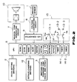
- Fig. 2 is a diagram illustrating the general structure of an electric circuit in wind instrument body 101 as shown in Figs. 1A through 1C.
- a CPU (central processing unit) 6 constituted by a microprocessor performs the general control of the electric circuit of the electronic wind instrument and controls the generation and tone off of a musical tone from a musical tone generating circuit 7.
- the first function of this CPU 6 is to receive pitch data from pitch-setting switches 2 that constitute the pitch-setting means and send the data to musical tone generating circuit 7.
- the second function of CPU 6 is to receive digital breath data generated in accordance with breath data from breath sensor 1 that constitutes breath sensor means and send the digital breath data to musical tone generating circuit 7 as tone generation start data and tone control data concerning tone volume, timbre, etc.
- the digital breath data is acquired by converting the breath data into a corresponding voltage value in a voltage-converting circuit 8 and then converting the voltage value into digital data in an A/D converter 9.
- the third function of CPU 6 is to receive pitch data from pitch-setting switches 2 and timbre/effect data selected by the operation of timbre/effect-changing switches 3 and send, to musical tone generating circuit 7 and a tone outputting device 10, a musical tone with a specific pitch and with specific timbre and effect set in accordance with the individual received.
- the fourth function of CPU 6 is such that, when the fingering operation of at least one of pitch-setting switches 2 is altered during breath manipulation in order to alter the pitch of a musical tone to be generated, CPU 6 sends, to musical tone generating circuit 7, new pitch data corresponding to the pitch newly set by the altered fingering operation upon elapse of a predetermined first delay time from the point of the alteration based on an instruction from a timer 14-1.
- the first delay time can be freely set by a player, and this setting is executed in the following procedure.
- delay time setting mode selecting switch 13-1 included in delay time setting switches 13 is operated so that switch 13-1 is coupled to a terminal DE applied with a predetermined voltage V DD .
- This predetermined voltage V DD is then applied to CPU 6 through this switch 13-1.
- switch 13-1 is coupled to a ground terminal ET, the ground potential is applied through this switch 13-1 to CPU 6, thus selecting the mode for variably setting the second delay time for octave-changing switches 12.
- the delay time setting mode being set for either pitch-setting switches 2 or octave-changing switches 12
- UP switch 13-2 when UP switch 13-2 is turned ON, a voltage Va is applied to CPU 6 and the delay time is set longer by a predetermined time, e.g., 5 msec, upon every ON operation of this switch 13-2.
- DOWN switch 13-3 When DOWN switch 13-3 is turned ON, however, a voltage Vb is applied to CPU 6 and the delay time is set shorter by a predetermined time, e.g., 5 msec, upon every ON operation of this switch 13-3. If UP switch 13-2 and DOWN switch 13-3 are simultaneously turned ON, the delay time is set at the middle value, for example, 20 msec.
- the fifth function of CPU 6 is such that, when the ON/OFF status of at least one of octave-changing switches 12 is changed by the changing operation of that switch 12 in order to alter the pitch set by the fingering operation of pitch-setting switches 2 by units of octave, CPU 6 outputs, to musical tone generating circuit 7, new pitch data or octave data for octave alteration which corresponds to the pitch newly set by the octave changing operation, not immediately but upon elapse of the predetermined second delay time from the point of the alteration, based on a tone generation start instruction from timer 14-2.
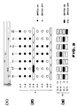
- Fig. 3 illustrates the relation between the individual notes of a score on a staff and the fingering operation of pitch-setting switches 2 and the operation status of octave-changing switches 12 in the electronic wind instrument according to the first embodiment.
- Fig. 3 (2) illustrates the fingering operation pitch-setting switches 2 corresponding to the pitches of the individual notes G4 to B3 indicated on the staff shown in Fig. 3 (1), the black circles indicating a switch ON state and the white circles indicating a switch OFF state.
- Fig. 3 (3) illustrates the operation of octave-changing switches 12 corresponding to the pitches of the individual notes G4 to B3 of the score shown in Fig. 3 (1), the black boxes indicating the octave-changing ON state and the white boxes indicating the octave-changing OFF state.
- pitch-setting switches 2-5 to 2-7 ON operation of pitch-setting switches 2-5 to 2-7 is performed for G4 with the left hand and octave-changing switch 2-1 is operated to be in the normal state with the left hand, thereby the pitch for G4 is set. Then, with respect to A4#, pitch-setting switch 2-5 is rendered OFF while keeping pitch-setting switches 2-6 and 2-7 in the ON state, and sharp switch 2-9 is rendered ON with the left hand.
- Octave-changing switch 12-1 is kept in the octave-changing state. Accordingly, the pitch of A4# is set.
- pitch-setting switch 2-5 is newly rendered ON and sharp switch 2-9 is rendered OFF with the left hand, and pitch-setting switches 2-4 and 2-3 are newly rendered ON with the right hand while switching octave-changing switch 12-1 to octave-changing switch 12-2 with the left hand. Accordingly, the pitch is altered to a pitch one higher by one octave.
- the pitch of D5 to that of D4 or alter the pitch of G4 to that of B3 the presently-set octave-changing switch is switched to octave-changing switch 12-1 or 12-4.
- Fig. 4 is a flowchart for variably setting the aforementioned first and second delay times, and this flow starts upon occurrence of a timer interrupt with respect to the main routine (not shown) of the operation of CPU 6 or is repeatedly executed at a predetermined timing.
- step 9-1 it is determined whether or not UP switch 13-2 of delay time setting switches 13 is rendered ON, and if YES in this step, it is then determined in step 9-2 whether or not "1" is set in the up-flag. If YES in step 9-2, which means that UP switch 13-2 has already been rendered ON, it is determined in step 9-3 whether or not DOWN switch is simultaneously rendered ON. If it is negative (NO) in the last step, no new process needs to be executed so that the flow returns to the main routine. However, if it is YES in step 9-3, which means that the selected switch operation is for setting the delay time to the middle value, in step 9-4, data "0" representing the middle value is set in an A buffer that serves to store delay time setting data.
- step 9-5 it is determined whether or not delay time setting mode selecting switch 13-1 is set in the mode to select pitch-setting switches 2. If YES in this step, which means that the mode for variably setting the first delay time with respect to pitch-setting switches 2 is set, middle value data "0" is written in a pitch timer buffer KEYTIM in step 9-6 and the flow returns to the main routine.
- the first delay time time corresponding to the middle value data, e.g., 20 msec
- the first delay time time corresponding to the middle value data, e.g., 20 msec
- step 9-5 which means that the mode is selected to variably set the second delay time with respect to octave-changing switches 12
- the middle value data "0" is written in an octave timer buffer OCTTIM in step 9-7 and the flow then returns to the main routine.
- the second delay time is set to output new octave alteration data corresponding to the pitch newly set by the switching operation to tone generating circuit 7 from timer 14-2 with a delay also corresponding to the middle value data from the point of alteration.
- step 9-2 which means that UP switch 13-2 has been newly rendered ON to newly alter the set delay time
- data "+1" for increasing the delay time by one step e.g., 5 msec
- step 9-9 it is determined whether or not delay time setting switch 13-1 is set in the mode to select pitch-setting switches 2.
- step 9-10 the data of the first delay time previously stored in pitch timer buffer KEYTIM is transferred to a B buffer in step 9-10, and the result of the addition of this data and the data set in A buffer in step 4-8 (i.e., +1 in this case) is set in pitch timer buffer KEYTIM in step 9-11.
- the flow then returns to the main routines. Consequently, the new delay time has been set which is the first delay time increased by one step in association with the present ON operation of UP switch 13-2.
- the mode is selected to variably set the second delay time to octave-changing switches 12
- the data previously stored in octave timer buffer OCTTIM is transferred to B buffer in step 9-12, and the result of the addition of this data and the data (+1) previously set in A buffer in step 9-13 is set in octave timer buffer OCTTIM step 9-13.
- the new delay time has been set which is the second delay time increased by one step in association with the present ON operation of UP switch 13-2, and the flow then returns to the main routines. If the data in B buffer is already the maximum value (e.g., +10) or minimum value (e.g., -10) in step 9-12, the content of B buffer will not be altered.
- step 9-1 If the decision in step 9-1 is NO, it means that UP switch 13-2 is not rendered ON, so that it is determined in step 9-14 whether or not the up-flag is "1.” If YES in this step, "0" is set to the up-flag to reset it to thereby indicate that UP switch 13-2 is not in the ON state, and the flow then advances to step 9-16. If the decision in step 9-14 is NO, it is unnecessary to set the up-flag again and the flow advances to step 9-16 without re-setting the flag. In step 9-16, it is determined whether or not DOWN switch 13-3 is rendered ON. If YES in this step, it is determined in step 9-17 whether or not "1" is set to the down-flag.
- step 9-3 If the decision here is YES, it means that DOWN switch 13-3 has already rendered ON, the flow advances to the aforementioned step 9-3 and the above-described process will be executed. (Its description will be omitted here to avoid redundancy.) If the decision in step 9-17 is NO, it means that DOWN switch 13-3 is presently rendered ON and the delay time is newly set shorter. In the subsequent step 9-18, data (-1) for shortening the delay time by one step (e.g., by 5 msec) is set in A buffer, and the flow advances to step 9-9. Then, the above-described process is similarly carried out to set the shortened first and second delay times, and the flow returns to the main routine.
- step 9-16 If the decision in step 9-16 is NO, it means that neither UP switch 13-2 nor DOWN switch 13-3 is not rendered ON, so that it is determined in step 9-19 whether or not "1" is set to the down-flag. If YES in this step, "0" is set to the down-flag in step 9-20 to indicate that DOWN switch 13-3 is not rendered ON this time, and the flow returns to the main routine. If the decision in step 9-19 is NO, since no alteration process is required, the flow returns to the main routine without carrying out any alteration.
- Fig. 5 is a flowchart for scanning the operation of pitch-setting switches 2 and octave-changing switch 12 in the electronic wind instrument according to the first embodiment, and this flow is a subroutine that repeatedly executed at given intervals with respect to the flow of the main routine (not shown) of CPU 6.
- step 10-1 the operated ON/OFF status of pitch-setting switches 2 is scanned, and pitch data set by pitch-setting switches 2 is read out and stored in present pitch data buffer NEWB.
- step 10-2 it is determined whether or not the present pitch data coincides with the previously-acquired pitch data stored in previous pitch data buffer OLDB. IF YES in this step, it means that no change occurs in the operation of pitch-setting switches 2 for altering the pitch, so that the flow advances to step 10-3.
- step 10-2 If the decision in step 10-2 is NO, which means that some change has occurred in the operation of pitch-setting switches 2, so that the flow advances to step 10-4 where data corresponding to the first delay time set in advance in a pitch timer buffer KEYTIM is set in a time buffer TIMBF incorporated in CPU 6 to be ready for measuring the first delay time before the flow advances to step 10-3.
- step 10-3 the switching operation status of octave-changing switches 12 is scanned and the octave alteration data set by octave-changing switches 12 is read out and stored in a present octave alteration data buffer NEWO.
- step 10-5 it is determined whether or not the present octave alteration data coincides with the previously acquired octave alteration data. If YES, the flow advances to step 10-6 where the pitch setting data acquired by the present scanning and stored in step 10-1 is added to the octave alteration data acquired by the present scanning and stored in step 10-3 and the resultant data is stored in present pitch data buffer KEYNEW and the flow advances to step 10-7.
- step 10-5 the old data stored in octave timer buffer OCTTIM in step 10-8 is transferred to time buffer TIMBF and the flow advances to step 10-6.
- step 10-6 the flow advances to step 10-7 where it is determined whether or not the content of present pitch data buffer KEYNEW coincides with the content of previous pitch data buffer KEYOLD, which is the pitch data acquired by the previous scanning. If YES, it means that no pitch alteration has occurred and it is unnecessary to output new pitch data, so that the flow returns to the main routine without further process.
- step 10-7 it is necessary to output new pitch data so that the flow advances to step 10-9 where it is determined whether or not "1" is set to the pitch change flags in timers 14-1 and 14-2. If YES, it means that timers 14-1 and 14-2 are already in counting action, so that the new pitch data stored in present pitch data buffer KEYNEW is transferred to previous pitch data buffer KEYOLD in step 10-10, and the flow returns to the main routine. If the decision in step 10-9 is NO, it means that timers 14-1 and 14-2 have not started the counting action yet and it is necessary to output new pitch data, so that "1" is set to each pitch change flag in the subsequent step 10-11.
- the delay time setting data corresponding to the first and second delay times which are set in advance in time buffer TIMBF, are respectively set to timers 14-1 and 14-2 incorporated in CPU 6, thereby starting the counting operation of the timers 14-1 and 14-2.
- the flow then returns to the main routine.
- scanning is executed to detect whether or not a change has occurred in the ON/OFF operation status of pitch-setting switches 2 or octave-changing switches 12 during the breath manipulation, and when such a change is detected, the counting operation of timers 14-1 and 14-2 are started which measure the elapse of the delay times for delaying, by set times, the output of pitch data to tone generating circuit 7 through CPU 6 from pitch-setting switches 2 or octave-changing switches 12.
- Fig. 6 is a flowchart for a pitch alteration process, and this flow causes a timer interrupt to the main routine.
- step 11-1 it is determined whether or not the value of digital breath data based on the breath data detected by breath sensor 1 through the blowing has exceeded a predetermined key-ON set value that indicates the start of tone generation. If YES, it is in key-ON state or a musical tone is being generated, the data stored in present pitch data buffer NEWB is sent out to tone generating circuit 7 to generate a musical tone with the pitch corresponding to this pitch data in step 11-2.
- step 11-3 the pitch change flags of timers 14-1 and 14-2 are reset to have a value of "0" to stop the counting action of these timers to be ready for the next alteration in the operation status of pitch-setting switches 2 and octave-changing switches 12.
- the flow then returns to the main routine, thereby completing the interrupt operation.
- step 11-1 If the decision in step 11-1 is NO, it means that the value of digital breath data has not yet reached the key-ON set value and it is not the time to instruct the start of tone generation, i.e., it is in a key-OFF state. In this case, the flow advances to step 11-3 and thereafter, the same processes as executed in the case of the key-ON state are performed before returning to the main routine.
- the pitch data altered by the fingering operation of pitch-setting switches 2 or the switching operation of octave-changing switches is supplied to tone generating circuit 7 when the digital breath data becomes equal to or greater than the key-ON set value.
- timers 14-1 and 14-2 are provided in CPU 6 exclusively for counting the delay times. Instead of using these timers 14-1 and 14-2, the number of the repetitive operation of the main routine may be counted to thereby count the delay times. In this case, with the main routine being repeatedly executed at a 4 msec tempo, the value of time buffer TIMBF needs to be 5 or 9, for example.
- tone generating circuit 7 when the fingering operation of pitch-setting switches 2 (2-1 to 2-8) is changed during the performance by the breath manipulation, new pitch data corresponding to the altered state is supplied to tone generating circuit 7, not immediately, but upon elapse of the predetermined first delay time (which is set in consideration of the time required to complete at least the proper and stable fingering operation) based on the tone generation start instruction from timer 14-1, and a musical tone with the new pitch corresponding to the altered fingering operation is generated from tone generating circuit 7 based on the pitch data.
- the predetermined first delay time which is set in consideration of the time required to complete at least the proper and stable fingering operation
- tone generating circuit 7 when the switching operation of octave-changing switches 12 is altered, new pitch data corresponding to the alteration is supplied to tone generating circuit 7, not immediately, but upon elapse of the predetermined second delay time (which is set in consideration of the time required to complete at least the proper and stable fingering operation, as per the first delay time involved in the operation change of pitch-setting switches 2) based on the tone generation start instruction from timer 14-2.
- the predetermined second delay time which is set in consideration of the time required to complete at least the proper and stable fingering operation, as per the first delay time involved in the operation change of pitch-setting switches 2 based on the tone generation start instruction from timer 14-2.
- the present instrument is designed such that the first and second delay times for delaying the output of pitch data by predetermined times can be arbitrarily set by means of timers 14-1 and 14-2 by a player in accordance with his or her playing skill. Accordingly, the delay times can be set in accordance with the level of the fingering operation and switching operation by the player, thus providing a significant effect and making the present instrument easy to play.
- the electronic wind instrument according to the second embodiment has the same general outline and the same electronic circuit arrangement as the instrument of the first embodiment, so that their detailed description will be omitted below.
- Fig. 7 is a flowchart for scanning the operation of the pitch-setting switches and octave-changing switches, and this is a subroutine that is repeatedly executed at a given timing with respect to the flow of the main routine (not shown) of CPU 6.
- step 12-1 the ON/OFF operation status of pitch-setting switches 2 is scanned and pitch data acquired by this scanning is stored in present pitch data buffer NEWB.
- step 12-2 it is determined whether or not the present pitch data coincides with the content (previously acquired pitch data) of previous pitch data buffer OLDB. If YES, it means that no change has occurred in the operation status of pitch-setting switches 2, so that the flow advances directly to step 12-3.
- step 12-2 If the decision in step 12-2 is NO, it means the occurrence of an operational change in these switches, so that the flow advances to step 12-4 where the first delay time (a relatively short delay time of 20 msec in this case since the fingering operation of pitch-setting switches 2 is performed with other fingers than the thumb and is thus relatively easy), which has been set in advance in pitch timer buffer KEYTIM through delay time setting switches 13 (see Figs. 1C and 2), is transferred to time buffer TIMB built in CPU 6. The flow then advances to step 12-3.
- the first delay time a relatively short delay time of 20 msec in this case since the fingering operation of pitch-setting switches 2 is performed with other fingers than the thumb and is thus relatively easy
- step 12-3 the switching operation status of octave-changing switches 12 is scanned and octave-changing data acquired by this scanning is stored in present octave alteration data buffer NEWO.
- step 12-5 it is determined whether or not the present octave alteration data coincides with the previously acquired octave alteration data. If YES, the flow advances to step 12-6 where the result of addition of the pitch set data acquired by the present scanning and stored in step 12-1 and the octave alteration data acquired by the present scanning and stored in step 12-3 is stored in present pitch data buffer KEYNEW before the flow advances to step 12-7.
- step 12-5 If the decision in step 12-5 is NO, the flow advances to step 12-8 where the second delay time (a relatively long delay time of 35 msec in this case since the switching operation of octave-changing switches 12 is performed with the thumb and is thus relatively easier as compared with the fingering operation of pitch-setting switches 2), which has been previously set in octave timer buffer OCTTIM through delay time setting switches 13 (see Fig. 1C and 2), is transferred to time buffer TIMB.
- step 12-6 the second delay time (a relatively long delay time of 35 msec in this case since the switching operation of octave-changing switches 12 is performed with the thumb and is thus relatively easier as compared with the fingering operation of pitch-setting switches 2), which has been previously set in octave timer buffer OCTTIM through delay time setting switches 13 (see Fig. 1C and 2), is transferred to time buffer TIMB.
- step 12-6 the second delay time
- step 12-7 If YES in step 12-7, no pitch alteration is made and it is unnecessary to output new pitch data, so that the flow returns to the main routine without further process. If the decision in step 12-7 is NO, however, it is necessary to output new pitch data so that the flow advances to step 12-9 where it is determined whether or not "1" is set to the pitch change flags in timers 14-1 and 14-2. If YES, timers 14-1 and 14-2 are in a counting operation, and the flow advances to step 12-10 where the pitch data stored in present pitch data buffer KEYNEW is transferred to previous pitch data buffer KEYOLD to be ready for the next scanning. The flow then returns to the main routine.
- step 12-9 If the decision in step 12-9 is NO, timers 14-1 and 14-2 have not started the time counting yet, and a new tone is to be generated, so that "1" is set to the pitch change flags in these timers in step 12-11.
- step 12-12 data corresponding to the first and second delay times set in advance in time buffer TIMBF are respectively set to built-in timers 14-1 and 14-2 of CPU 6 to start the counting operation of these timers in order to delay the output of pitch data by a predetermined time at the time of pitch alteration. The flow then returns to the main routine.
- the musical tone of A4# is generated with a delay of the first delay time (e.g., 20 msec) that is set in advance in association with a change in the operation of pitch-setting switches 2.
- the musical tone of E5 is generated with a delay of the second delay time (e.g., 35 msec) that is set longer than the first delay time in advance.
- timers 14-1 and 14-2 are incorporated in CPU 6 to count the individual delay times according to the second embodiment, this design may be modified to count the number of the main routine executed.
- the second delay time (35 msec in this embodiment) for the switching operation of octave-changing switches 12 is set longer than the first delay time (20 msec in this embodiment) for the fingering operation of pitch-setting switches 2-1 to 2-8, so that the output timing of pitch data can be delayed by a time sufficient to complete the switching operation of octave-changing switches 12 which is required a higher skill than the fingering operation of pitch-setting switches 2. It is therefore possible to prevent temporary generation of musical tone at the undesired pitch at the time the switching operation of octave-changing switches 12 is executed.
- the delay time may be set longer, e.g., 45 msec, and when a change occurs only in the operation of octave-changing switches 12, the delay time may be set to 35 msec.
- tone generating circuit 7 and tone outputting device 10 may be separately provided as external units in such a way that these units can be electrically coupled to wind instrument body 101.
- the outline of the present electronic wind instrument is not restricted to be that of a saxophone, but may take other forms, such as the outline of a clarinet.
Description
- The present invention relates to an electronic wind instrument according to the preamble of
claim 1. - Electronic wind instruments of that generic type generally detect the breath manipulation of a player, as an electric signal, by means of a breath sensor provided at the mouthpiece and generate a musical tone with a pitch specified by a plurality of pitch-setting switches (first pitch designation means) provided on the musical instrument body, in accordance with the detected electric signal.
- Unlike electronic keyboard instruments, the electronic wind instruments of this type specify one pitch by a combined operation of pitch-setting switches. When one pitch is altered to another, therefore, it is necessary to perform simultaneous OFF operation of a plurality of pitch-setting switches that have been operated in combination in advance and immediately perform simultaneous ON operation of another group or combination of pitch-setting switches. This operation requires skill and causes even skilled players to have a period in which the proper fingering operation is not performed, thus generating a musical tone with the undesired, improper pitch during that transient instance.
- A solution of this problem is disclosed in US-A-3,767,833. An electronic wind instrument known therefrom is provided with a tone stopping circuit which temporarily stops tone generation during octave shifting in order to prevent a musical tone with the undesired pitch being generated during this octave shifting. With this instrument, however, tone generation is stopped even temporarily during a musical performance and the music played would not have the effect of natural and smooth volume change.
- Further, there would be a significant difference in level of the fingering operation technique between unskilled and skilled players, and the above problem cannot be solved simply for all kinds of players.
- Furthermore, with the use of an electronic wind instrument of this type, an octave changing switch (i.e. a second pitch designation means) is operated to increase or reduce the pitch set by the pitch-setting switches by units of an octave. As the octave-changing operation is normally performed by a player's thumb, this operation is particularly difficult when compared with the pitch altering operation by the pitch-setting switches. It is therefore difficult to perform the octave changing operation in synchronism with the fingering operation of the pitch-setting switches. In this case, there also arises a problem that a musical tone with the undesired pitch is generated while the pitch specified by the pitch-setting switches is altered to another pitch of a predetermined octave higher or lower, by operating the octave-changing switch.
- The a.m. problems partially can be solved by an electronic wind instrument as it is known from US-A-4 038 895 which document discloses an instrument of the type as indicated in the preamble of
claim 1. Namely, this known instrument further comprises detection means which are responsive to a change in a pitch due to a setting operation of the pitch designation means for generating a timing signal which indicates the respective instant of this change and, furthermore, a delay means which - in response to the timing signal - delays the generation of a newly set tone for a predetermined elapse time. By these measures it is possible to surely prevent the generation of a musical tone with an undesired pitch. This known instrument, however, is still disadvantageous in that the predetermined elapse time must be set such that it has a time duration which is adapted to both types of pitch designation means (i.e. the pitch setting switches and the octave-changing switch) and, consequently, must be set to a value which takes into account the worst case during both types of pitch changing operations. Thus, the time needed to perform the whole pitch change is comparatively long. - It therefore is the object of the present invention to improve an electronic wind instrument according to the preamble of
claim 1 in such a way that the time needed to perform the pitch change is as short as possible. - This object according to the present invention is solved by the advantageous measures indicated in the characterizing part of
claim 1. - By these measures it is possible to individually adapt the elapse time to both types of pitch designating means; the elapse time can therefore be made as short as appropriate for each type of pitch designating means, the whole pitch change thus being as short as possible.
- This invention can be more fully understood from the following detailed description when taken in conjunction with the accompanying drawings, in which:
- Figs. 1A through 1C are respectively front, back and left side views illustrating the outline of an electronic wind instrument according to this invention;
- Fig. 2 is a diagram illustrating the general arrangement of an electric circuit used in this electronic wind instrument;
- Fig. 3 is a diagram for explaining the fingering operation of pitch-setting switches;
- Fig. 4 is a flowchart for variably setting a delay time;
- Fig. 5 is a flowchart for scanning the operation of pitch-setting switches and octave-changing switches;
- Fig. 6 is a flowchart for a pitch alteration process; and
- Fig. 7 is a flowchart for scanning the operation of pitch-setting switches and octave-changing switches in an electronic wind instrument according to the second embodiment of this invention.
- Preferred embodiments of this invention will be described below with reference to the accompanying drawings.
- The first embodiment of this invention will be described below.
- Figs. 1A through 1C are respectively front, back and left side views illustrating the outline of the electronic wind instrument according to the first embodiment of this invention.
- A
wind instrument body 101 is provided with abreath sensor 1 for detecting the strength, or the amount, of breath applied to a mouthpiece 101a, pitch-setting switches 2 (2-1 to 2-8) for setting the pitch of a musical tone to be generated, timbre/effect changing switches 3, aspeaker 4 and apower switch 5. - At the back of
wind instrument body 101 are provided octave-changingswitches 12 for altering a pitch set by the fingering operation of pitch-setting switches 2 by units of octave and setting it. The octave-changingswitches 12 include a normal setting switch 12-1 for setting the pitch set by pitch-setting switches 2, a 1 octave-up switch 12-2 for altering and setting the pitch set by pitch-setting switches 2 to a pitch one octave higher, a 2 octave-up switch 12-3 for altering and setting the pitch set by pitch-setting switches 2 to a pitch two octaves higher, and a 1 octave-down switch 12-4 for altering and setting the pitch set by pitch-setting switches 2 to a pitch one octave lower. - At the side of
wind instrument body 101 are provided delaytime setting switches 13 that constitute delay time variable setting means. The delaytime setting switches 13 include a delay time setting mode selecting switch 13-1 for selecting which one of the first and second delay times should be variably set, and UP switch 13-2 and DOWN switch 13-3 for independently changing the first and second delay times by a predetermined time unit; the first delay time is a time set for delaying the output of pitch data corresponding to a pitch newly set by a change, when occurred, in the fingering operation of pitch-setting switches 2, by a predetermined time from the point of the change, and the second delay time is a time set for delaying the output of pitch data corresponding to a pitch newly set by a change, when occurred, in the changing operation of octave-changingswitches 12, by a predetermined time from the point of the change. - Fig. 2 is a diagram illustrating the general structure of an electric circuit in
wind instrument body 101 as shown in Figs. 1A through 1C. - A CPU (central processing unit) 6 constituted by a microprocessor performs the general control of the electric circuit of the electronic wind instrument and controls the generation and tone off of a musical tone from a musical
tone generating circuit 7. - The first function of this
CPU 6 is to receive pitch data from pitch-setting switches 2 that constitute the pitch-setting means and send the data to musicaltone generating circuit 7. - The second function of
CPU 6 is to receive digital breath data generated in accordance with breath data frombreath sensor 1 that constitutes breath sensor means and send the digital breath data to musicaltone generating circuit 7 as tone generation start data and tone control data concerning tone volume, timbre, etc. The digital breath data is acquired by converting the breath data into a corresponding voltage value in a voltage-convertingcircuit 8 and then converting the voltage value into digital data in an A/D converter 9. - The third function of
CPU 6 is to receive pitch data from pitch-setting switches 2 and timbre/effect data selected by the operation of timbre/effect-changingswitches 3 and send, to musicaltone generating circuit 7 and atone outputting device 10, a musical tone with a specific pitch and with specific timbre and effect set in accordance with the individual received. - The fourth function of
CPU 6 is such that, when the fingering operation of at least one of pitch-setting switches 2 is altered during breath manipulation in order to alter the pitch of a musical tone to be generated,CPU 6 sends, to musicaltone generating circuit 7, new pitch data corresponding to the pitch newly set by the altered fingering operation upon elapse of a predetermined first delay time from the point of the alteration based on an instruction from a timer 14-1. In this case, the first delay time can be freely set by a player, and this setting is executed in the following procedure. - First, delay time setting mode selecting switch 13-1 included in delay
time setting switches 13 is operated so that switch 13-1 is coupled to a terminal DE applied with a predetermined voltage VDD. This predetermined voltage VDD is then applied toCPU 6 through this switch 13-1. This selects the mode for variably setting the first delay time for pitch-setting switches 2. On the other hand, when switch 13-1 is coupled to a ground terminal ET, the ground potential is applied through this switch 13-1 toCPU 6, thus selecting the mode for variably setting the second delay time for octave-changingswitches 12. With the delay time setting mode being set for either pitch-setting switches 2 or octave-changingswitches 12, when UP switch 13-2 is turned ON, a voltage Va is applied toCPU 6 and the delay time is set longer by a predetermined time, e.g., 5 msec, upon every ON operation of this switch 13-2. When DOWN switch 13-3 is turned ON, however, a voltage Vb is applied toCPU 6 and the delay time is set shorter by a predetermined time, e.g., 5 msec, upon every ON operation of this switch 13-3. If UP switch 13-2 and DOWN switch 13-3 are simultaneously turned ON, the delay time is set at the middle value, for example, 20 msec. - The fifth function of
CPU 6 is such that, when the ON/OFF status of at least one of octave-changingswitches 12 is changed by the changing operation of thatswitch 12 in order to alter the pitch set by the fingering operation of pitch-setting switches 2 by units of octave,CPU 6 outputs, to musicaltone generating circuit 7, new pitch data or octave data for octave alteration which corresponds to the pitch newly set by the octave changing operation, not immediately but upon elapse of the predetermined second delay time from the point of the alteration, based on a tone generation start instruction from timer 14-2. - Fig. 3 illustrates the relation between the individual notes of a score on a staff and the fingering operation of pitch-
setting switches 2 and the operation status of octave-changingswitches 12 in the electronic wind instrument according to the first embodiment. - Fig. 3 (2) illustrates the fingering operation pitch-
setting switches 2 corresponding to the pitches of the individual notes G₄ to B₃ indicated on the staff shown in Fig. 3 (1), the black circles indicating a switch ON state and the white circles indicating a switch OFF state. Fig. 3 (3) illustrates the operation of octave-changingswitches 12 corresponding to the pitches of the individual notes G₄ to B₃ of the score shown in Fig. 3 (1), the black boxes indicating the octave-changing ON state and the white boxes indicating the octave-changing OFF state. - For instance, to set the pitch of the first note G₄ shown in Fig. 3 (1) and then alter the pitch to that of the next note A₄#, the following operation will be executed.
- First, ON operation of pitch-setting switches 2-5 to 2-7 is performed for G₄ with the left hand and octave-changing switch 2-1 is operated to be in the normal state with the left hand, thereby the pitch for G₄ is set. Then, with respect to A₄#, pitch-setting switch 2-5 is rendered OFF while keeping pitch-setting switches 2-6 and 2-7 in the ON state, and sharp switch 2-9 is rendered ON with the left hand. Octave-changing switch 12-1 is kept in the octave-changing state. Accordingly, the pitch of A₄# is set. To further alter the pitch to the pitch of the third note E₅ from that of A₄#, pitch-setting switch 2-5 is newly rendered ON and sharp switch 2-9 is rendered OFF with the left hand, and pitch-setting switches 2-4 and 2-3 are newly rendered ON with the right hand while switching octave-changing switch 12-1 to octave-changing switch 12-2 with the left hand. Accordingly, the pitch is altered to a pitch one higher by one octave. To alter the pitch of D₅ to that of D₄ or alter the pitch of G₄ to that of B₃, the presently-set octave-changing switch is switched to octave-changing switch 12-1 or 12-4.
- Fig. 4 is a flowchart for variably setting the aforementioned first and second delay times, and this flow starts upon occurrence of a timer interrupt with respect to the main routine (not shown) of the operation of
CPU 6 or is repeatedly executed at a predetermined timing. - First, in step 9-1, it is determined whether or not UP switch 13-2 of delay time setting switches 13 is rendered ON, and if YES in this step, it is then determined in step 9-2 whether or not "1" is set in the up-flag. If YES in step 9-2, which means that UP switch 13-2 has already been rendered ON, it is determined in step 9-3 whether or not DOWN switch is simultaneously rendered ON. If it is negative (NO) in the last step, no new process needs to be executed so that the flow returns to the main routine. However, if it is YES in step 9-3, which means that the selected switch operation is for setting the delay time to the middle value, in step 9-4, data "0" representing the middle value is set in an A buffer that serves to store delay time setting data. In the subsequent step 9-5, it is determined whether or not delay time setting mode selecting switch 13-1 is set in the mode to select pitch-setting
switches 2. If YES in this step, which means that the mode for variably setting the first delay time with respect to pitch-settingswitches 2 is set, middle value data "0" is written in a pitch timer buffer KEYTIM in step 9-6 and the flow returns to the main routine. As a result, with the fingering operation of pitch-settingswitches 2 being altered, the first delay time (time corresponding to the middle value data, e.g., 20 msec) is set to output new pitch data corresponding to the pitch newly set by the alteration to tone generatingcircuit 7 from timer 14-1 upon elapse of a predetermined delay time from the point of alteration. - If it is NO in step 9-5, which means that the mode is selected to variably set the second delay time with respect to octave-changing
switches 12, the middle value data "0" is written in an octave timer buffer OCTTIM in step 9-7 and the flow then returns to the main routine. As a result, similarly, with the switching operation of octave-changingswitches 12 being performed, the second delay time is set to output new octave alteration data corresponding to the pitch newly set by the switching operation to tone generatingcircuit 7 from timer 14-2 with a delay also corresponding to the middle value data from the point of alteration. - If it is NO in step 9-2, which means that UP switch 13-2 has been newly rendered ON to newly alter the set delay time, data "+1" for increasing the delay time by one step (e.g., 5 msec) is set in A buffer in step 9-8. The flow then advances to step 9-9 where it is determined whether or not delay time setting switch 13-1 is set in the mode to select pitch-setting
switches 2. If YES in this step, which means that the mode is selected to variably set the first delay time to pitch-settingswitches 2, the data of the first delay time previously stored in pitch timer buffer KEYTIM is transferred to a B buffer in step 9-10, and the result of the addition of this data and the data set in A buffer in step 4-8 (i.e., +1 in this case) is set in pitch timer buffer KEYTIM in step 9-11. The flow then returns to the main routines. Consequently, the new delay time has been set which is the first delay time increased by one step in association with the present ON operation of UP switch 13-2. - IF the decision is NO in step 9-9, it means that the mode is selected to variably set the second delay time to octave-changing
switches 12, the data previously stored in octave timer buffer OCTTIM is transferred to B buffer in step 9-12, and the result of the addition of this data and the data (+1) previously set in A buffer in step 9-13 is set in octave timer buffer OCTTIM step 9-13. Accordingly, the new delay time has been set which is the second delay time increased by one step in association with the present ON operation of UP switch 13-2, and the flow then returns to the main routines. If the data in B buffer is already the maximum value (e.g., +10) or minimum value (e.g., -10) in step 9-12, the content of B buffer will not be altered. - If the decision in step 9-1 is NO, it means that UP switch 13-2 is not rendered ON, so that it is determined in step 9-14 whether or not the up-flag is "1." If YES in this step, "0" is set to the up-flag to reset it to thereby indicate that UP switch 13-2 is not in the ON state, and the flow then advances to step 9-16. If the decision in step 9-14 is NO, it is unnecessary to set the up-flag again and the flow advances to step 9-16 without re-setting the flag. In step 9-16, it is determined whether or not DOWN switch 13-3 is rendered ON. If YES in this step, it is determined in step 9-17 whether or not "1" is set to the down-flag. If the decision here is YES, it means that DOWN switch 13-3 has already rendered ON, the flow advances to the aforementioned step 9-3 and the above-described process will be executed. (Its description will be omitted here to avoid redundancy.) If the decision in step 9-17 is NO, it means that DOWN switch 13-3 is presently rendered ON and the delay time is newly set shorter. In the subsequent step 9-18, data (-1) for shortening the delay time by one step (e.g., by 5 msec) is set in A buffer, and the flow advances to step 9-9. Then, the above-described process is similarly carried out to set the shortened first and second delay times, and the flow returns to the main routine. If the decision in step 9-16 is NO, it means that neither UP switch 13-2 nor DOWN switch 13-3 is not rendered ON, so that it is determined in step 9-19 whether or not "1" is set to the down-flag. If YES in this step, "0" is set to the down-flag in step 9-20 to indicate that DOWN switch 13-3 is not rendered ON this time, and the flow returns to the main routine. If the decision in step 9-19 is NO, since no alteration process is required, the flow returns to the main routine without carrying out any alteration.
- Fig. 5 is a flowchart for scanning the operation of pitch-setting
switches 2 and octave-changingswitch 12 in the electronic wind instrument according to the first embodiment, and this flow is a subroutine that repeatedly executed at given intervals with respect to the flow of the main routine (not shown) ofCPU 6. - First, in step 10-1, the operated ON/OFF status of pitch-setting
switches 2 is scanned, and pitch data set by pitch-settingswitches 2 is read out and stored in present pitch data buffer NEWB. In the subsequent step 10-2, it is determined whether or not the present pitch data coincides with the previously-acquired pitch data stored in previous pitch data buffer OLDB. IF YES in this step, it means that no change occurs in the operation of pitch-settingswitches 2 for altering the pitch, so that the flow advances to step 10-3. If the decision in step 10-2 is NO, which means that some change has occurred in the operation of pitch-settingswitches 2, so that the flow advances to step 10-4 where data corresponding to the first delay time set in advance in a pitch timer buffer KEYTIM is set in a time buffer TIMBF incorporated inCPU 6 to be ready for measuring the first delay time before the flow advances to step 10-3. - In step 10-3, the switching operation status of octave-changing
switches 12 is scanned and the octave alteration data set by octave-changingswitches 12 is read out and stored in a present octave alteration data buffer NEWO. In the next step 10-5, it is determined whether or not the present octave alteration data coincides with the previously acquired octave alteration data. If YES, the flow advances to step 10-6 where the pitch setting data acquired by the present scanning and stored in step 10-1 is added to the octave alteration data acquired by the present scanning and stored in step 10-3 and the resultant data is stored in present pitch data buffer KEYNEW and the flow advances to step 10-7. If the decision in step 10-5 is NO, the old data stored in octave timer buffer OCTTIM in step 10-8 is transferred to time buffer TIMBF and the flow advances to step 10-6. After executing step 10-6, the flow advances to step 10-7 where it is determined whether or not the content of present pitch data buffer KEYNEW coincides with the content of previous pitch data buffer KEYOLD, which is the pitch data acquired by the previous scanning. If YES, it means that no pitch alteration has occurred and it is unnecessary to output new pitch data, so that the flow returns to the main routine without further process. If the decision in step 10-7 is NO, it is necessary to output new pitch data so that the flow advances to step 10-9 where it is determined whether or not "1" is set to the pitch change flags in timers 14-1 and 14-2. If YES, it means that timers 14-1 and 14-2 are already in counting action, so that the new pitch data stored in present pitch data buffer KEYNEW is transferred to previous pitch data buffer KEYOLD in step 10-10, and the flow returns to the main routine. If the decision in step 10-9 is NO, it means that timers 14-1 and 14-2 have not started the counting action yet and it is necessary to output new pitch data, so that "1" is set to each pitch change flag in the subsequent step 10-11. In the subsequent step 10-12, the delay time setting data corresponding to the first and second delay times, which are set in advance in time buffer TIMBF, are respectively set to timers 14-1 and 14-2 incorporated inCPU 6, thereby starting the counting operation of the timers 14-1 and 14-2. The flow then returns to the main routine. - As described above, in the scan flow, scanning is executed to detect whether or not a change has occurred in the ON/OFF operation status of pitch-setting
switches 2 or octave-changingswitches 12 during the breath manipulation, and when such a change is detected, the counting operation of timers 14-1 and 14-2 are started which measure the elapse of the delay times for delaying, by set times, the output of pitch data to tone generatingcircuit 7 throughCPU 6 from pitch-settingswitches 2 or octave-changingswitches 12. - Fig. 6 is a flowchart for a pitch alteration process, and this flow causes a timer interrupt to the main routine.
- First, in step 11-1 it is determined whether or not the value of digital breath data based on the breath data detected by
breath sensor 1 through the blowing has exceeded a predetermined key-ON set value that indicates the start of tone generation. If YES, it is in key-ON state or a musical tone is being generated, the data stored in present pitch data buffer NEWB is sent out to tone generatingcircuit 7 to generate a musical tone with the pitch corresponding to this pitch data in step 11-2. - In the subsequent step 11-3, the pitch change flags of timers 14-1 and 14-2 are reset to have a value of "0" to stop the counting action of these timers to be ready for the next alteration in the operation status of pitch-setting
switches 2 and octave-changingswitches 12. The flow then returns to the main routine, thereby completing the interrupt operation. - If the decision in step 11-1 is NO, it means that the value of digital breath data has not yet reached the key-ON set value and it is not the time to instruct the start of tone generation, i.e., it is in a key-OFF state. In this case, the flow advances to step 11-3 and thereafter, the same processes as executed in the case of the key-ON state are performed before returning to the main routine.
- As should be understood from the above, in this flow, the pitch data altered by the fingering operation of pitch-setting
switches 2 or the switching operation of octave-changing switches is supplied to tone generatingcircuit 7 when the digital breath data becomes equal to or greater than the key-ON set value. - In the above embodiment, timers 14-1 and 14-2 are provided in
CPU 6 exclusively for counting the delay times. Instead of using these timers 14-1 and 14-2, the number of the repetitive operation of the main routine may be counted to thereby count the delay times. In this case, with the main routine being repeatedly executed at a 4 msec tempo, the value of time buffer TIMBF needs to be 5 or 9, for example. - As described above, with the electronic wind instrument according to the first embodiment, when the fingering operation of pitch-setting switches 2 (2-1 to 2-8) is changed during the performance by the breath manipulation, new pitch data corresponding to the altered state is supplied to tone generating
circuit 7, not immediately, but upon elapse of the predetermined first delay time (which is set in consideration of the time required to complete at least the proper and stable fingering operation) based on the tone generation start instruction from timer 14-1, and a musical tone with the new pitch corresponding to the altered fingering operation is generated fromtone generating circuit 7 based on the pitch data. Similarly, when the switching operation of octave-changingswitches 12 is altered, new pitch data corresponding to the alteration is supplied to tone generatingcircuit 7, not immediately, but upon elapse of the predetermined second delay time (which is set in consideration of the time required to complete at least the proper and stable fingering operation, as per the first delay time involved in the operation change of pitch-setting switches 2) based on the tone generation start instruction from timer 14-2. Therefore, it is possible to prevent a musical tone with the undesired pitch from being generated even in a transient status where the fingering operation of pitch-settingswitches 2 and the switching operation of octave-changingswitches 12 are not stable at predetermined operation statuses, that is, when the operational timings of a plurality of pitch-setting switches 2-1 to 2-7 involving a plurality of fingers are not synchronized such that the individual pitch-setting switches 2-1 to 2-7 are operated with some time delays. It is also possible to prevent generation of a musical tone with the undesired pitch even when the operational timings of pitch-setting switches 2-1 to 2-7 are not synchronized with the switching operation timings of the individual octave-changing switches 12-1 to 12-4. Further, since, unlike the conventional instrument, no tone stopping circuit is provided, pitch alteration can be executed in a smooth continuous tone-generation state without stopping the tone generation even temporarily, so that a music can be played in a natural tone-generation state. - Furthermore, the present instrument is designed such that the first and second delay times for delaying the output of pitch data by predetermined times can be arbitrarily set by means of timers 14-1 and 14-2 by a player in accordance with his or her playing skill. Accordingly, the delay times can be set in accordance with the level of the fingering operation and switching operation by the player, thus providing a significant effect and making the present instrument easy to play.
- The electronic wind instrument according to the second embodiment has the same general outline and the same electronic circuit arrangement as the instrument of the first embodiment, so that their detailed description will be omitted below.
- Fig. 7 is a flowchart for scanning the operation of the pitch-setting switches and octave-changing switches, and this is a subroutine that is repeatedly executed at a given timing with respect to the flow of the main routine (not shown) of
CPU 6. - First, in step 12-1, the ON/OFF operation status of pitch-setting
switches 2 is scanned and pitch data acquired by this scanning is stored in present pitch data buffer NEWB. In the next step 12-2, it is determined whether or not the present pitch data coincides with the content (previously acquired pitch data) of previous pitch data buffer OLDB. If YES, it means that no change has occurred in the operation status of pitch-settingswitches 2, so that the flow advances directly to step 12-3. If the decision in step 12-2 is NO, it means the occurrence of an operational change in these switches, so that the flow advances to step 12-4 where the first delay time (a relatively short delay time of 20 msec in this case since the fingering operation of pitch-settingswitches 2 is performed with other fingers than the thumb and is thus relatively easy), which has been set in advance in pitch timer buffer KEYTIM through delay time setting switches 13 (see Figs. 1C and 2), is transferred to time buffer TIMB built inCPU 6. The flow then advances to step 12-3. - In step 12-3, the switching operation status of octave-changing
switches 12 is scanned and octave-changing data acquired by this scanning is stored in present octave alteration data buffer NEWO. In the subsequent step 12-5, it is determined whether or not the present octave alteration data coincides with the previously acquired octave alteration data. If YES, the flow advances to step 12-6 where the result of addition of the pitch set data acquired by the present scanning and stored in step 12-1 and the octave alteration data acquired by the present scanning and stored in step 12-3 is stored in present pitch data buffer KEYNEW before the flow advances to step 12-7. If the decision in step 12-5 is NO, the flow advances to step 12-8 where the second delay time (a relatively long delay time of 35 msec in this case since the switching operation of octave-changingswitches 12 is performed with the thumb and is thus relatively easier as compared with the fingering operation of pitch-setting switches 2), which has been previously set in octave timer buffer OCTTIM through delay time setting switches 13 (see Fig. 1C and 2), is transferred to time buffer TIMB. The flow then advances to step 12-6 followed by step 12-7 where it is determined whether or not the content of present pitch data buffer KEYNEW coincides with the content of previous pitch data buffer KEYOLD. If YES in step 12-7, no pitch alteration is made and it is unnecessary to output new pitch data, so that the flow returns to the main routine without further process. If the decision in step 12-7 is NO, however, it is necessary to output new pitch data so that the flow advances to step 12-9 where it is determined whether or not "1" is set to the pitch change flags in timers 14-1 and 14-2. If YES, timers 14-1 and 14-2 are in a counting operation, and the flow advances to step 12-10 where the pitch data stored in present pitch data buffer KEYNEW is transferred to previous pitch data buffer KEYOLD to be ready for the next scanning. The flow then returns to the main routine. If the decision in step 12-9 is NO, timers 14-1 and 14-2 have not started the time counting yet, and a new tone is to be generated, so that "1" is set to the pitch change flags in these timers in step 12-11. In the subsequent step 12-12, data corresponding to the first and second delay times set in advance in time buffer TIMBF are respectively set to built-in timers 14-1 and 14-2 ofCPU 6 to start the counting operation of these timers in order to delay the output of pitch data by a predetermined time at the time of pitch alteration. The flow then returns to the main routine. - Referring to Fig. 3, a description will be given of the statuses of the fingering operation of pitch-setting
switches 2 and the switching operation of octave-changingswitches 12 in the electronic wind instrument according to the second embodiment. - When the playing of the first note G₄ is changed to the playing of the next note A₄#, since no alteration is made to the switching operation of octave-changing
switches 12, the musical tone of A₄# is generated with a delay of the first delay time (e.g., 20 msec) that is set in advance in association with a change in the operation of pitch-settingswitches 2. With regard to alteration to the pitch of E₅ from that of A₄#, since a change occurs both in pitch-settingswitches 2 and octave-changingswitches 12, the musical tone of E₅ is generated with a delay of the second delay time (e.g., 35 msec) that is set longer than the first delay time in advance. With regard to alteration to D₅ from E₅, since no change also occurs in the operation octave-changingswitches 12, the generation of the musical tone of D₅ is delayed by the first delay time (20 msec). With regard to alteration to D₄ from D₅, since a change occurs in the operation of octave-changingswitches 12 though no change occurs in the operation of pitch-settingswitches 2, the generation of the musical tone of D₄ is delayed by the second delay time (35 msec). Similarly, the intended musical tone will be delayed by the first delay time for alteration to G₄ from D₄ and by the second delay time for alteration to B₃ from G₄. In other words, according to the second embodiment, when a change occurs in the switching operation of octave-changingswitches 12, the start of the output of pitch data is delayed by the second delay time set longer than the first delay time that has been set to pitch-settingswitches 2. - Since the pitch alteration operation of
CPU 6 in the second embodiment is the same as that involved in the first embodiment (see Fig. 6), its description will be omitted below. - Although timers 14-1 and 14-2 are incorporated in
CPU 6 to count the individual delay times according to the second embodiment, this design may be modified to count the number of the main routine executed. - According to the second embodiment, unlike in the first embodiment, the second delay time (35 msec in this embodiment) for the switching operation of octave-changing
switches 12 is set longer than the first delay time (20 msec in this embodiment) for the fingering operation of pitch-setting switches 2-1 to 2-8, so that the output timing of pitch data can be delayed by a time sufficient to complete the switching operation of octave-changingswitches 12 which is required a higher skill than the fingering operation of pitch-settingswitches 2. It is therefore possible to prevent temporary generation of musical tone at the undesired pitch at the time the switching operation of octave-changingswitches 12 is executed. This eliminates the need to make the first delay time for the fingering operation of pitch-settingswitches 2 coincide with the second delay time for octave-changingswitches 12 and can thus permit the first delay time to be set sufficiently short. Even a quick trill is performed by the pitch setting operation through pitch-settingswitches 2, therefore, it is possible to prevent the output of the pitch data after a change in the fingering operation from being delayed more than necessary. - When a change occurs both in the operations of pitch-setting
switches 2 and octave-changingswitches 12, the delay time may be set longer, e.g., 45 msec, and when a change occurs only in the operation of octave-changingswitches 12, the delay time may be set to 35 msec. - Unlike the first and second embodiments,
tone generating circuit 7 and tone outputtingdevice 10 may be separately provided as external units in such a way that these units can be electrically coupled towind instrument body 101. - Further, the outline of the present electronic wind instrument is not restricted to be that of a saxophone, but may take other forms, such as the outline of a clarinet.
Claims (8)
- An electronic wind instrument, comprising:[a] a wind instrument body (101);[b1] a plurality of first pitch designation means (2: 2-1 to 2-7) for setting a pitch of a musical tone which is to be generated by the unit of a half or a whole tone;[b2] at least one second pitch designation means (12: 12-1 to 12-4) for altering a respective pitch set by one of said first pitch designation means (2: 2-1 to 2-7) by the unit of an octave and for setting this altered pitch;[b3] said first and second pitch designation means (2: 2-1 to 2-7, 12: 12-1 to 12-4) being provided on said body (101);[c] breath sensor means (1) being provided on said body (101) for generating a breath sense signal;[d] tone generation instructing means (6) for instructing the generation of a tone at a respective pitch set by said first and second pitch designation means (2: 2-1 to 2-7, 12: 12-1 to 12-4) on the basis of said breath sense signal;[e] detection means (6) being responsive to a change in a pitch due to a setting operation of said first and second pitch designation means (2: 2-1 to 2-7, 12: 12-1 to 12-4) for generating a timing signal which indicates the respective instant of said change; and[f] delay means (6, 7) which - in response to said timing signal - delays the generation of a newly set tone for a predetermined elapse time;
characterized in that[e1] said detection means (6) is adapted to independently detect a change in a pitch of said first and second pitch designation means (2: 2-1 to 2-7, 12: 12-1 to 12-4), respectively, and to generate corresponding first and second timing signals; and[f1] said delay means (6, 7) attributes to said first and second pitch designation means (2: 2-1 to 2-7, 12: 12-1 to 12-4) a first and second delay time, respectively, and - in response to said first or second timing signal - delays the generation of a newly set tone for said first respectively second elapse time. - An electronic wind instrument according to claim 1, characterized in that said delay means (6, 7) includes counter means (14-1, 14-2) which - upon receipt of said first respectively second timing signal - starts a count operation and permits output of pitch data corresponding to a newly set pitch when a predetermined count value is reached.
- An electronic wind instrument according to claim 1 or 2, characterized by tone generating means (7, 10) which - when a pitch setting operation of said first and second pitch designation means (2: 2-1 to 2-7, 12: 12-1 to 12-4) is executed - generates a musical tone at a pitch set by said pitch setting operation.
- An electronic wind instrument according to claim 3, characterized in that said tone generating means (7, 10) is provided at said wind instrument body (101).
- An electronic wind instrument according to one of claims 1 through 4, characterized in that said delay means (6, 7) includes time setting means (13) capable of arbitrarily setting said first and second elapse time.
- An electronic wind instrument according to one of claims 1 through 5, characterized in that said first and second delay time have the same duration.
- An electronic wind instrument according to one of claims 1 through 6, characterized in that the duration of said second delay time is longer than the duration of said first delay time.
- An electronic wind instrument according to one of claims 1 through 7, characterized by delay time setting means (14-1, 14-2) capable of variably setting a respective duration of said first and second delay time to an arbitrary value.
Applications Claiming Priority (6)
| Application Number | Priority Date | Filing Date | Title |
|---|---|---|---|
| JP200157/87U | 1987-12-28 | ||
| JP20015787 | 1987-12-28 | ||
| JP63204818A JP2604431B2 (en) | 1987-12-28 | 1988-08-19 | Electronic wind instrument |
| JP204818/88 | 1988-08-19 | ||
| JP10834388U JPH0412558Y2 (en) | 1988-08-19 | 1988-08-19 | |
| JP108343/88U | 1988-08-19 |
Publications (3)
| Publication Number | Publication Date |
|---|---|
| EP0322846A2 EP0322846A2 (en) | 1989-07-05 |
| EP0322846A3 EP0322846A3 (en) | 1990-02-14 |
| EP0322846B1 true EP0322846B1 (en) | 1993-03-17 |
Family
ID=27311210
Family Applications (1)
| Application Number | Title | Priority Date | Filing Date |
|---|---|---|---|
| EP88121689A Expired - Lifetime EP0322846B1 (en) | 1987-12-28 | 1988-12-27 | Electronic wind instrument with a pitch data delay function |
Country Status (3)
| Country | Link |
|---|---|
| US (1) | US4919032A (en) |
| EP (1) | EP0322846B1 (en) |
| DE (1) | DE3879443T2 (en) |
Families Citing this family (15)
| Publication number | Priority date | Publication date | Assignee | Title |
|---|---|---|---|---|
| JPH01172100U (en) * | 1988-05-23 | 1989-12-06 | ||
| JP2591121B2 (en) * | 1988-06-17 | 1997-03-19 | カシオ計算機株式会社 | Chord setting device and electronic wind instrument |
| US5286911A (en) * | 1988-09-20 | 1994-02-15 | Casio Computer Co., Ltd. | Electronic rubbed-string instrument |
| US5403966A (en) * | 1989-01-04 | 1995-04-04 | Yamaha Corporation | Electronic musical instrument with tone generation control |
| US5119712A (en) * | 1989-01-19 | 1992-06-09 | Casio Computer Co., Ltd. | Control apparatus for electronic musical instrument |
| JP2893724B2 (en) * | 1989-06-12 | 1999-05-24 | ヤマハ株式会社 | Music signal generator |
| US5300729A (en) * | 1989-06-19 | 1994-04-05 | Yamaha Corporation | Electronic musical instrument having operator with selective control function |
| JP2508339B2 (en) * | 1990-02-14 | 1996-06-19 | ヤマハ株式会社 | Musical tone signal generator |
| JP3307287B2 (en) * | 1997-07-29 | 2002-07-24 | ヤマハ株式会社 | Electronic wind instrument |
| JP4218663B2 (en) * | 2005-06-21 | 2009-02-04 | ヤマハ株式会社 | Wind instrument key detection structure |
| JP4258498B2 (en) * | 2005-07-25 | 2009-04-30 | ヤマハ株式会社 | Sound control device and program for wind instrument |
| US7723605B2 (en) * | 2006-03-28 | 2010-05-25 | Bruce Gremo | Flute controller driven dynamic synthesis system |
| DE102006038687A1 (en) * | 2006-08-17 | 2008-02-21 | Pieverling, Klaus von, Dr. | Organ e.g. pipe organ, registering method, involves storing register positions of organ pieces in memory, and consecutively interpolating register positions by switching signal during playing selected notes |
| JP6435644B2 (en) * | 2014-05-29 | 2018-12-12 | カシオ計算機株式会社 | Electronic musical instrument, pronunciation control method and program |
| JP7419880B2 (en) * | 2020-03-02 | 2024-01-23 | ヤマハ株式会社 | electronic wind instrument |
Family Cites Families (7)
| Publication number | Priority date | Publication date | Assignee | Title |
|---|---|---|---|---|
| US3767833A (en) * | 1971-10-05 | 1973-10-23 | Computone Inc | Electronic musical instrument |
| JPS5427134B2 (en) * | 1973-05-24 | 1979-09-07 | ||
| US3938419A (en) * | 1974-05-20 | 1976-02-17 | David De Rosa | Electronic musical instrument |
| US4074233A (en) * | 1976-06-30 | 1978-02-14 | Norlin Music, Inc. | Selection switch memory circuit |
| US4038895A (en) * | 1976-07-02 | 1977-08-02 | Clement Laboratories | Breath pressure actuated electronic musical instrument |
| US4418599A (en) * | 1982-04-08 | 1983-12-06 | Raskin Gregory D | Electronic signal level control apparatus for acoustical-electrical transducer instrument |
| US4757737A (en) * | 1986-03-27 | 1988-07-19 | Ugo Conti | Whistle synthesizer |
-
1988
- 1988-12-20 US US07/287,405 patent/US4919032A/en not_active Expired - Lifetime
- 1988-12-27 DE DE88121689T patent/DE3879443T2/en not_active Expired - Fee Related
- 1988-12-27 EP EP88121689A patent/EP0322846B1/en not_active Expired - Lifetime
Also Published As
| Publication number | Publication date |
|---|---|
| DE3879443T2 (en) | 1993-10-21 |
| US4919032A (en) | 1990-04-24 |
| EP0322846A2 (en) | 1989-07-05 |
| DE3879443D1 (en) | 1993-04-22 |
| EP0322846A3 (en) | 1990-02-14 |
Similar Documents
| Publication | Publication Date | Title |
|---|---|---|
| EP0322846B1 (en) | Electronic wind instrument with a pitch data delay function | |
| US4993307A (en) | Electronic musical instrument with a coupler effect function | |
| US5208416A (en) | Automatic performance device | |
| US5247864A (en) | Display apparatus for electronic musical instrument | |
| US6541688B2 (en) | Electronic musical instrument with performance assistance function | |
| US8802956B2 (en) | Automatic accompaniment apparatus for electronic keyboard musical instrument and fractional chord determination apparatus used in the same | |
| CN112150994B (en) | Electronic organ blank beat sound insertion auxiliary device, tone color switching signal generation method and computer readable storage medium | |
| JP3844286B2 (en) | Automatic accompaniment device for electronic musical instruments | |
| US5300728A (en) | Method and apparatus for adjusting the tempo of auto-accompaniment tones at the end/beginning of a bar for an electronic musical instrument | |
| JP2745215B2 (en) | Electronic string instrument | |
| JPH0412558Y2 (en) | ||
| Wright | A comparison of MIDI and ZIPI | |
| JP2006065186A (en) | Device and method for tempo information output, computer program for tempo information output, device and method for touch information output, and computer program for touch information output | |
| JP3609045B2 (en) | Automatic performance device | |
| JPS6248833B2 (en) | ||
| US5418324A (en) | Auto-play apparatus for generation of accompaniment tones with a controllable tone-up level | |
| JP3296202B2 (en) | Performance operation instruction device | |
| JP2604431B2 (en) | Electronic wind instrument | |
| JP2552002B2 (en) | Electronic instrument tone color setting method | |
| JP4172335B2 (en) | Automatic accompaniment generator and program | |
| JP2900360B2 (en) | Automatic accompaniment device | |
| JPH05150768A (en) | Electronic stringed instrument | |
| US4350069A (en) | Automatic bass generator for electronic organ | |
| JP2578327B2 (en) | Automatic performance device | |
| JPH02705B2 (en) |
Legal Events
| Date | Code | Title | Description |
|---|---|---|---|
| PUAI | Public reference made under article 153(3) epc to a published international application that has entered the european phase |
Free format text: ORIGINAL CODE: 0009012 |
|
| AK | Designated contracting states |
Kind code of ref document: A2 Designated state(s): DE FR GB IT |
|
| PUAL | Search report despatched |
Free format text: ORIGINAL CODE: 0009013 |
|
| AK | Designated contracting states |
Kind code of ref document: A3 Designated state(s): DE FR GB IT |
|
| 17P | Request for examination filed |
Effective date: 19900625 |
|
| 17Q | First examination report despatched |
Effective date: 19910802 |
|
| GRAA | (expected) grant |
Free format text: ORIGINAL CODE: 0009210 |
|
| AK | Designated contracting states |
Kind code of ref document: B1 Designated state(s): DE FR GB IT |
|
| REF | Corresponds to: |
Ref document number: 3879443 Country of ref document: DE Date of ref document: 19930422 |
|
| ITF | It: translation for a ep patent filed |
Owner name: BUGNION S.P.A. |
|
| ET | Fr: translation filed | ||
| PLBE | No opposition filed within time limit |
Free format text: ORIGINAL CODE: 0009261 |
|
| STAA | Information on the status of an ep patent application or granted ep patent |
Free format text: STATUS: NO OPPOSITION FILED WITHIN TIME LIMIT |
|
| 26N | No opposition filed | ||
| PGFP | Annual fee paid to national office [announced via postgrant information from national office to epo] |
Ref country code: FR Payment date: 19961211 Year of fee payment: 9 |
|
| PGFP | Annual fee paid to national office [announced via postgrant information from national office to epo] |
Ref country code: DE Payment date: 19970107 Year of fee payment: 9 |
|
| PGFP | Annual fee paid to national office [announced via postgrant information from national office to epo] |
Ref country code: GB Payment date: 19971218 Year of fee payment: 10 |
|
| PG25 | Lapsed in a contracting state [announced via postgrant information from national office to epo] |
Ref country code: FR Free format text: THE PATENT HAS BEEN ANNULLED BY A DECISION OF A NATIONAL AUTHORITY Effective date: 19971231 |
|
| PG25 | Lapsed in a contracting state [announced via postgrant information from national office to epo] |
Ref country code: DE Free format text: LAPSE BECAUSE OF NON-PAYMENT OF DUE FEES Effective date: 19980901 |
|
| REG | Reference to a national code |
Ref country code: FR Ref legal event code: ST |
|
| PG25 | Lapsed in a contracting state [announced via postgrant information from national office to epo] |
Ref country code: GB Free format text: LAPSE BECAUSE OF NON-PAYMENT OF DUE FEES Effective date: 19981227 |
|
| GBPC | Gb: european patent ceased through non-payment of renewal fee |
Effective date: 19981227 |
|
| PG25 | Lapsed in a contracting state [announced via postgrant information from national office to epo] |
Ref country code: IT Free format text: LAPSE BECAUSE OF NON-PAYMENT OF DUE FEES;WARNING: LAPSES OF ITALIAN PATENTS WITH EFFECTIVE DATE BEFORE 2007 MAY HAVE OCCURRED AT ANY TIME BEFORE 2007. THE CORRECT EFFECTIVE DATE MAY BE DIFFERENT FROM THE ONE RECORDED. Effective date: 20051227 |