EP0322642A2 - Connectors - Google Patents
Connectors Download PDFInfo
- Publication number
- EP0322642A2 EP0322642A2 EP88120882A EP88120882A EP0322642A2 EP 0322642 A2 EP0322642 A2 EP 0322642A2 EP 88120882 A EP88120882 A EP 88120882A EP 88120882 A EP88120882 A EP 88120882A EP 0322642 A2 EP0322642 A2 EP 0322642A2
- Authority
- EP
- European Patent Office
- Prior art keywords
- segments
- plug
- pieces
- socket
- regular hexagonal
- Prior art date
- Legal status (The legal status is an assumption and is not a legal conclusion. Google has not performed a legal analysis and makes no representation as to the accuracy of the status listed.)
- Withdrawn
Links
Images


Classifications
-
- H—ELECTRICITY
- H01—ELECTRIC ELEMENTS
- H01R—ELECTRICALLY-CONDUCTIVE CONNECTIONS; STRUCTURAL ASSOCIATIONS OF A PLURALITY OF MUTUALLY-INSULATED ELECTRICAL CONNECTING ELEMENTS; COUPLING DEVICES; CURRENT COLLECTORS
- H01R13/00—Details of coupling devices of the kinds covered by groups H01R12/70 or H01R24/00 - H01R33/00
- H01R13/02—Contact members
- H01R13/15—Pins, blades or sockets having separate spring member for producing or increasing contact pressure
- H01R13/18—Pins, blades or sockets having separate spring member for producing or increasing contact pressure with the spring member surrounding the socket
Definitions
- This invention relates to connectors for use in hanging bell type ambient electric furnaces, mobile power source vehicle tap changing and the like, and particular to connectors in which 6 pieces of segments each of which is formed of regular hexagonal plug inserting hole in its center and a spring band for clamping the 6 pieces of the assembled segments with its centripetal force are provided.
- connectors for example, connecting devices for hanging bell type ambient electric furnaces, mobile power source vehicle tap changing and the like
- plug type members have been provided, but in the conventional connecting devices of this kind, a socket that becomes the stationary side, if there is a center offset in the insertion of plug, cannot correspond to the center offset and also, if an inserting angle of the plug is not appropriate, a gap is produced on a contact surface formed between the plug and the socket thereby reducing a contact area, and causing a burnout trouble easily resulting from an inferior contact, and moreover, since the socket is formed of a closed structure, the elastic force of groove formed on the socket is lost by the burnout which is resulted in more frequent inferior contacts, shortening the service life, and furthermore, in the large size plug type connecting devices of the conventional structure, the manufacture thereof is difficult which are used for connection of large electric current of 2000 to 3000 ampares, or super large capacity such as 36 KV to 168 KV which have been drawbacks.
- An object of this invention is to provide a socket in which 6 pieces of electric conductive bars whose cross section is a regular hexagonal cross section are bundled to form a plug inserting hole of a regular hexagonal cross section in its center, and a spring band is provided to clamp the 6 pieces of the assembled segments with its centripetal force, and the 6 pieces of the segments forming the socket make an independent operation without restricting other segments mutually and having contact pressure, and make a corresponding operation positively against the center offset and an error of an inserting angle when the plug is inserted so that the contact pressure is applied by each segment simultaneously against the inserted plug and thus, the complete contact with the plug is maintained.
- An object of this invention is to provide a socket capable of radiating heat through a gap formed between the 6 pieces of the segments, said gap being formed by inserting the plug into the socket consisting of the 6 pieces of the segments clamped with the spring band so that a rise of temperature is limited to a minimum, and is capable of making a self cleaning action of discharging foreign matters in the socket through the gap.
- Another object of this invention is to provide a socket formed in such a way that its structure is formed by assembling the 6 pieces of the segments with a stationary band in the rear part of the segments, and the 6 pieces of the segments forming the socket which are clamped by the spring band to provide a regular hexagonal plug inserting hole in its center and to give a centripetal force operate independently and having an independent contact pressure so that the socket is capable of eliminating the apprehensions of causing the inferior contacts resulting from irregular bundling of each segment by the repulsive force of the magnetic power working at the instant of the entering of the plug, failing to make the simultaneous contact of the 6 pieces of the segments with the plug which produce the contact in disorder with an instant time lag or resulting from an out of balance of the whole 6 pieces of the segments due to the insertion of one piece of the segment or the specific segment only into the rear part by and advancement of the plug which causes the retreat of the segment.
- the foregoing socket is capable of eliminating the
- a further object of this invention is to provide a socket by assembling the 6 pieces of the segments of electric conductive bars whose cross section is a regular hexagonal shape to form a plug inserting hole of a regular hexagonal shape in its center, and the socket proper employs a means of inserting a plug into the plug inserting hole from both ends of the socket proper to connect a primary side and a secondary side by means of the plug, and a pressure bonding terminal of cord is connected to a flat surface type terminal portion of each plug of the primary side and the secondary side by the face contact so that the connection with the face contact is made possible by enlarging the contact area of the terminal portion to a maximum, and a plurality of bolts and nuts are used to clamp the segments according to the rating whereby the energization is taken place at a high efficiency.
- FIG. 1 is a perspective view of a socket A according to a first embodiment of this invention, and the socket A is formed by assembling 6 pieces of segments shown in FIG. 2.
- the segment 1, as shown in FIGS. 5, 6 and 8, is formed in a regular hexagonal shape from an electric conductive bar, and said 6 pieces of the segments 1 are bundled and assembled to form a plug inserting hole 2 of a regular hexagonal shape.
- the 6 pieces of the assembled segments 1 are clamped by a spring band 4 which provides a centripetal force to the segments.
- the 6 pieces of the segments 1 are assembled by a stationary ring 3 provided at its rear part.
- a plug B shown in FIG. 4 is inserted into the plug inserting hole 2 of the socket A as shown in FIG. 7 whereby the plug B and the socket A are connected.
- the 6 pieces of the segments 1 are formed. with concave grooves 6, 6 for insertion of the spring band 4 at two locations which are adjacent to the front surface of the strip groove 5 of the front and rear part, and a concave groove 8 is formed to mount a mounting plate 7 to be described hereinafter between the two pieces of the concave grooves 6, 6 of back and forth locations.
- the segments are clamped by the centripetal force of the spring band 4, and the socket A is installed on the mounting plate 7 as shown in FIG. 9.
- the mounting plate 7 is installed on support frames 13 erected at right and left of a base 12, and the mounting plate 7 is retained and installed to be shiftable against the support surface, and the concave groove 8 of the socket A is fitted in a through hole 14 of the support plate 7 and thus, a center axis of the socket A is tiltable in an optional direction.
- each segment 1 of the socket A is connected to one end of a flat cable 17 by means of a terminal bolt 16, and the other end is connected to a terminal end 18 of the base 12.
- the socket A is formed in such a way that a taper portion 10 is provided on a tip portion of the surface formed with an inserting hole 2 of each segment 1 and 1a to form an inserting opening 9 of the plug inserting hole 2 in trumpet type.
- the plug B is formed of a columnar shaft whose diameter is slightly larger than that of the plug inserting hole 2 of the socket A, and when this plug B is fitted into the plug inserting hole 2 of the socket A, a gap 11 is formed in spaces of the 6 pieces of the segments 1.
- the 6 pieces of the segments 1 forming a regular hexagonal cross section are bundled to provide a plug inserting hole 2 of a hexagonal cross section in its center and the 6 pieces of the segments are assembled and retained by a stationary ring 3 at the rear part of the 6 piece of the segments, and the 6 pieces of the assembled segments 1 are clamped by the spring band 4 to form the socket A by its centripetal force, and this socket A is constructed in such a way that the 6 pieces of the segments 1 perform an independent operation without restricting the other segments mutually.
- the segments 1 perform the repulsive action individually upon the working of the repul sive force of the magnetic power at an instant of the entering of the plug B, but at this time, in order to prevent the repulsion of the 6 pieces of the segments in disorder or to prevent the retreat of the specific one piece or more than one piece of the segments upon being inserted into the rear part, the 6 pieces of the segments 1 are caused to be repulsive uniformly as the whole by the locking action of the stationary ring 3, and the 6 pieces of the segments 1 can be contacted with the plug B simultaneously and completely.
- the 6 pieces of the assembled segments which perform the independent operation without restricting other segments mutually and having the contact pressure perform the positive operation against the center offset of the plug or the error of the inserting angle and apply the contact pressure simultaneously against the plug by the segments whereby the complete contact with the plug can be maintained. Furthermore, the 6 pieces of the segments 1 clamped by the spring band 4 produce the gap 11 between the 6 pieces of the segments 1 as a result of the enlargement of the socket A by resisting the spring band 2 when the plug B is inserted, and the heat radiation action is caused through the gap 11 to minimize the temperature rise and to effect the self cleaning action of discharging the foreign matters in the socket A through the gap 11.
- the socket A is formed by the easy assemblage of the 5 pieces of the segments 1 having the strip groove 5 for fitting the stationary ring 3 and one piece of the segment 1a having the notch 5a to provide the abutting surface which abuts the stationary ring 3.
- the socket A installed on the mounting plate 7 is constructed in such a way that the center axis of the socket A is made to be eccentric according to the transfer of the mounting plate 7 and at the same time, the center axis of the socket A is made tiltable in an optional direction, and its posture is controlled automatically in correspondence to the center offset of the plug B or the error of the inserting angle thereof and moreover, after the insertion of the plug B, the 6 pieces of the segments operating independently without restricting other segments 1 mutually and having the contact pressure automatically absorb and control the center offset or the error of the inserting angle of the plug B to ensure the complete and positive contact between the plug B and the socket A.
- FIG. 10 through FIG. 15 show a second embodiment according to this invention, and in this embodiment, the plug B′ is inserted into both ends of the socket A′ to connect a primary side and a secondary side by means of the plug, and thus, a connector to be used for electric connection of large electric current in the order of 36 KV to 168 KV is provided.
- the socket A′ shown in FIG. 10 in this embodiment is formed by assembling the 6 pieces of the segments 101 shown in FIG. 11, and the segments 101 are formed in a regular hexagonal shape cross section from an electric conductive bar, and as shown in FIG. 10 through FIG. 13, the 6 pieces of the segments 101 are bundled and assembled to form a regular hexagonal shape plug inserting hole 102 in its center and the 6 pieces of the assembled segments 101 are clamped by the centripetal force of the spring band 104, and the 6 pieces of the segments 101 are formed with a plurality of concave grooves 106 for insertion of the spring band 104 at a fixed interval from the front part to the rear part.
- taper portions 110, 110′ are formed on both end portions of the surface forming the inserting hole 102 of each segment 101, and the plug B′ shown in FIG. 12 is inserted into the plug inserting hole 102 through both ends of the socket A′ as shown in FIG. 13.
- the plugs B′, B′ are inserted into the plug inserting hole 102 through the inserting openings 109, 109′ of both ends of the socket A′ whereby the primary side and the secondary side are connected by means of the plugs B′, B′, and the terminal portion 119 of the plugs B′ is formed in a flat surface on which a plurality of mounting holes 123 are formed for connection and fixing of pressure bonding terminal 122 by the bolt 120, nut 121 whereby the complete positive connection is provided by the surface contact because of the large area of the terminal portion 119 of the plug B′, and the efficient energization is carried out by clamping with the use of the bolt 120 and nut 121 through a plurality of mounting holes 123 according to the ratings, electric connection of the super large electric current, the desired large electric current, for example, in the order of 36 KV to 168 KV can be effected without apprehension and without limitation of the energy volume by the size of the pressure bonding terminal
- the socket A′ prepared by assembling the 6 pieces of the segments 101 with the centripetal force of the spring band 104 is constructed in such a way that each of the 6 pieces of the segments 101 operates independently to provide the contact pressure.
- the plug B′ inserted to the secondary side of the socket A′ provides the locking operation with its flange portion 124 so that only one piece or more than two pieces of the specific segments are inserted to be retreated by the contact of each segment 101 with the plug B′ by the repulsive force of the magnetic force working at an instant of the entering of the plug B from the primary side in disordered condition or the advancement of the plug B′, and the whole of the 6 pieces of the segments 101 are uniformly caused to be repulsive and thus, the 6 pieces of the segments 101 make simultaneous and complete contacting against the plug B′.
Abstract
Description
- This invention relates to connectors for use in hanging bell type ambient electric furnaces, mobile power source vehicle tap changing and the like, and particular to connectors in which 6 pieces of segments each of which is formed of regular hexagonal plug inserting hole in its center and a spring band for clamping the 6 pieces of the assembled segments with its centripetal force are provided.
- Heretofore, as connectors, for example, connecting devices for hanging bell type ambient electric furnaces, mobile power source vehicle tap changing and the like, plug type members have been provided, but in the conventional connecting devices of this kind, a socket that becomes the stationary side, if there is a center offset in the insertion of plug, cannot correspond to the center offset and also, if an inserting angle of the plug is not appropriate, a gap is produced on a contact surface formed between the plug and the socket thereby reducing a contact area, and causing a burnout trouble easily resulting from an inferior contact, and moreover, since the socket is formed of a closed structure, the elastic force of groove formed on the socket is lost by the burnout which is resulted in more frequent inferior contacts, shortening the service life, and furthermore, in the large size plug type connecting devices of the conventional structure, the manufacture thereof is difficult which are used for connection of large electric current of 2000 to 3000 ampares, or super large capacity such as 36 KV to 168 KV which have been drawbacks.
- An object of this invention is to provide a socket in which 6 pieces of electric conductive bars whose cross section is a regular hexagonal cross section are bundled to form a plug inserting hole of a regular hexagonal cross section in its center, and a spring band is provided to clamp the 6 pieces of the assembled segments with its centripetal force, and the 6 pieces of the segments forming the socket make an independent operation without restricting other segments mutually and having contact pressure, and make a corresponding operation positively against the center offset and an error of an inserting angle when the plug is inserted so that the contact pressure is applied by each segment simultaneously against the inserted plug and thus, the complete contact with the plug is maintained.
- An object of this invention is to provide a socket capable of radiating heat through a gap formed between the 6 pieces of the segments, said gap being formed by inserting the plug into the socket consisting of the 6 pieces of the segments clamped with the spring band so that a rise of temperature is limited to a minimum, and is capable of making a self cleaning action of discharging foreign matters in the socket through the gap.
- Another object of this invention is to provide a socket formed in such a way that its structure is formed by assembling the 6 pieces of the segments with a stationary band in the rear part of the segments, and the 6 pieces of the segments forming the socket which are clamped by the spring band to provide a regular hexagonal plug inserting hole in its center and to give a centripetal force operate independently and having an independent contact pressure so that the socket is capable of eliminating the apprehensions of causing the inferior contacts resulting from irregular bundling of each segment by the repulsive force of the magnetic power working at the instant of the entering of the plug, failing to make the simultaneous contact of the 6 pieces of the segments with the plug which produce the contact in disorder with an instant time lag or resulting from an out of balance of the whole 6 pieces of the segments due to the insertion of one piece of the segment or the specific segment only into the rear part by and advancement of the plug which causes the retreat of the segment. Furthermore, the foregoing socket is capable of eliminating the occurrence of the burnout trouble due to the inferior contact completely by causing the 6 pieces of the segments to contact the plug simultaneously and completely when the plug enters the socket.
- A further object of this invention is to provide a socket by assembling the 6 pieces of the segments of electric conductive bars whose cross section is a regular hexagonal shape to form a plug inserting hole of a regular hexagonal shape in its center, and the socket proper employs a means of inserting a plug into the plug inserting hole from both ends of the socket proper to connect a primary side and a secondary side by means of the plug, and a pressure bonding terminal of cord is connected to a flat surface type terminal portion of each plug of the primary side and the secondary side by the face contact so that the connection with the face contact is made possible by enlarging the contact area of the terminal portion to a maximum, and a plurality of bolts and nuts are used to clamp the segments according to the rating whereby the energization is taken place at a high efficiency.
-
- FIG. 1 is a perspective view of a socket consisting of the 6 pieces of the assembled segments;
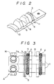
- FIG. 2 is a perspective view of the segment;
- FIG. 3 is a side view of the socket;
- FIG. 4 is a side view of the plug;
- FIG. 5 is an elevation of the socket;
- FIG. 6 is a rear view of the socket;
- FIG. 7 is a cross section showing the plug inserted into the socket;
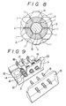
- FIG. 8 is a cross section taken along a line Y-Y of FIG. 7;
- FIG. 9 is a perspective view showing that the socket and the plug are installed on a support base respectively;
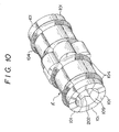
- FIG. 10 is a perspective view of the socket of a second embodiment of this invention;
- FIG. 11 is a perspective view of the segment;
- FIG. 12 is a perspective view of the plug;
- FIG. 13 is a cross section showing that the plug is inserted into the socket;
- FIG. 14 is a side view of the socket; and
- FIG. 15 is a cross section taken along a line Y-Y of FIG. 13.
- FIG. 1 is a perspective view of a socket A according to a first embodiment of this invention, and the socket A is formed by assembling 6 pieces of segments shown in FIG. 2. The segment 1, as shown in FIGS. 5, 6 and 8, is formed in a regular hexagonal shape from an electric conductive bar, and said 6 pieces of the segments 1 are bundled and assembled to form a
plug inserting hole 2 of a regular hexagonal shape. The 6 pieces of the assembled segments 1 are clamped by aspring band 4 which provides a centripetal force to the segments. The 6 pieces of the segments 1 are assembled by astationary ring 3 provided at its rear part. A plug B shown in FIG. 4 is inserted into theplug inserting hole 2 of the socket A as shown in FIG. 7 whereby the plug B and the socket A are connected. - In the 6 pieces of the segments 1 forming the socket A, 5 pieces of the segments 1... out of the 6 pieces of the segments are formed with a
strip groove 5 for the insertion of thestationary ring 3, and the remaining one piece of the segment 1a is formed in such a way that a rear part from the location corresponding to thestrip groove 5 of the segment 1 is notched 5a and is removed to form a low flat surface to the rear end. In the assembly of the socket A, initially, thestationary ring 3 is fitted in eachstrip groove 5 upon assemblage to form theplug inserting hole 2 in its center by the 5 pieces of the segments 1... having thestrip groove 5, and finally, the segment 1a having thenotch 5a is incorporated into the 5 pieces of the segments 1... by abutting and positioning thenotch 5a at thestationary ring 3 whereby the 5 pieces of the segments 1... and the remaining one piece of the segment 1a are assembled and retained. - Furthermore, the 6 pieces of the segments 1 are formed. with concave grooves 6, 6 for insertion of the
spring band 4 at two locations which are adjacent to the front surface of thestrip groove 5 of the front and rear part, and aconcave groove 8 is formed to mount a mounting plate 7 to be described hereinafter between the two pieces of the concave grooves 6, 6 of back and forth locations. The segments are clamped by the centripetal force of thespring band 4, and the socket A is installed on the mounting plate 7 as shown in FIG. 9. - The mounting plate 7 is installed on
support frames 13 erected at right and left of abase 12, and the mounting plate 7 is retained and installed to be shiftable against the support surface, and theconcave groove 8 of the socket A is fitted in a throughhole 14 of the support plate 7 and thus, a center axis of the socket A is tiltable in an optional direction. - By the way, in FIG. 9, the plug B is shown in the condition of being installed on the
support base 15. A rear end of each segment 1 of the socket A is connected to one end of a flat cable 17 by means of aterminal bolt 16, and the other end is connected to aterminal end 18 of thebase 12. - The socket A is formed in such a way that a
taper portion 10 is provided on a tip portion of the surface formed with aninserting hole 2 of each segment 1 and 1a to form an inserting opening 9 of theplug inserting hole 2 in trumpet type. - The plug B is formed of a columnar shaft whose diameter is slightly larger than that of the
plug inserting hole 2 of the socket A, and when this plug B is fitted into theplug inserting hole 2 of the socket A, agap 11 is formed in spaces of the 6 pieces of the segments 1. - Accordingly, the 6 pieces of the segments 1 forming a regular hexagonal cross section are bundled to provide a
plug inserting hole 2 of a hexagonal cross section in its center and the 6 pieces of the segments are assembled and retained by astationary ring 3 at the rear part of the 6 piece of the segments, and the 6 pieces of the assembled segments 1 are clamped by thespring band 4 to form the socket A by its centripetal force, and this socket A is constructed in such a way that the 6 pieces of the segments 1 perform an independent operation without restricting the other segments mutually. The segments 1 perform the repulsive action individually upon the working of the repul sive force of the magnetic power at an instant of the entering of the plug B, but at this time, in order to prevent the repulsion of the 6 pieces of the segments in disorder or to prevent the retreat of the specific one piece or more than one piece of the segments upon being inserted into the rear part, the 6 pieces of the segments 1 are caused to be repulsive uniformly as the whole by the locking action of thestationary ring 3, and the 6 pieces of the segments 1 can be contacted with the plug B simultaneously and completely. The 6 pieces of the assembled segments which perform the independent operation without restricting other segments mutually and having the contact pressure perform the positive operation against the center offset of the plug or the error of the inserting angle and apply the contact pressure simultaneously against the plug by the segments whereby the complete contact with the plug can be maintained. Furthermore, the 6 pieces of the segments 1 clamped by thespring band 4 produce thegap 11 between the 6 pieces of the segments 1 as a result of the enlargement of the socket A by resisting thespring band 2 when the plug B is inserted, and the heat radiation action is caused through thegap 11 to minimize the temperature rise and to effect the self cleaning action of discharging the foreign matters in the socket A through thegap 11. - The socket A is formed by the easy assemblage of the 5 pieces of the segments 1 having the
strip groove 5 for fitting thestationary ring 3 and one piece of the segment 1a having thenotch 5a to provide the abutting surface which abuts thestationary ring 3. - The socket A installed on the mounting plate 7 is constructed in such a way that the center axis of the socket A is made to be eccentric according to the transfer of the mounting plate 7 and at the same time, the center axis of the socket A is made tiltable in an optional direction, and its posture is controlled automatically in correspondence to the center offset of the plug B or the error of the inserting angle thereof and moreover, after the insertion of the plug B, the 6 pieces of the segments operating independently without restricting other segments 1 mutually and having the contact pressure automatically absorb and control the center offset or the error of the inserting angle of the plug B to ensure the complete and positive contact between the plug B and the socket A.
- FIG. 10 through FIG. 15 show a second embodiment according to this invention, and in this embodiment, the plug B′ is inserted into both ends of the socket A′ to connect a primary side and a secondary side by means of the plug, and thus, a connector to be used for electric connection of large electric current in the order of 36 KV to 168 KV is provided.
- The socket A′ shown in FIG. 10 in this embodiment is formed by assembling the 6 pieces of the
segments 101 shown in FIG. 11, and thesegments 101 are formed in a regular hexagonal shape cross section from an electric conductive bar, and as shown in FIG. 10 through FIG. 13, the 6 pieces of thesegments 101 are bundled and assembled to form a regular hexagonal shapeplug inserting hole 102 in its center and the 6 pieces of the assembledsegments 101 are clamped by the centripetal force of thespring band 104, and the 6 pieces of thesegments 101 are formed with a plurality ofconcave grooves 106 for insertion of thespring band 104 at a fixed interval from the front part to the rear part. At both ends of the socket A′, in order to form theinserting openings taper portions inserting hole 102 of eachsegment 101, and the plug B′ shown in FIG. 12 is inserted into theplug inserting hole 102 through both ends of the socket A′ as shown in FIG. 13. Namely, in the second embodiment, wherein the plugs B′, B′ are inserted into theplug inserting hole 102 through theinserting openings terminal portion 119 of the plugs B′ is formed in a flat surface on which a plurality ofmounting holes 123 are formed for connection and fixing of pressure bonding terminal 122 by thebolt 120,nut 121 whereby the complete positive connection is provided by the surface contact because of the large area of theterminal portion 119 of the plug B′, and the efficient energization is carried out by clamping with the use of thebolt 120 andnut 121 through a plurality ofmounting holes 123 according to the ratings, electric connection of the super large electric current, the desired large electric current, for example, in the order of 36 KV to 168 KV can be effected without apprehension and without limitation of the energy volume by the size of the pressure bonding terminal like the screw type for connection of the pressure bonding terminal in the socket A of the first embodiment with thebolt 16 or the size of the lead wire. - Also, in the second embodiment, the socket A′ prepared by assembling the 6 pieces of the
segments 101 with the centripetal force of thespring band 104 is constructed in such a way that each of the 6 pieces of thesegments 101 operates independently to provide the contact pressure. The plug B′ inserted to the secondary side of the socket A′ provides the locking operation with itsflange portion 124 so that only one piece or more than two pieces of the specific segments are inserted to be retreated by the contact of eachsegment 101 with the plug B′ by the repulsive force of the magnetic force working at an instant of the entering of the plug B from the primary side in disordered condition or the advancement of the plug B′, and the whole of the 6 pieces of thesegments 101 are uniformly caused to be repulsive and thus, the 6 pieces of thesegments 101 make simultaneous and complete contacting against the plug B′.
Claims (4)
- (1) A connector comprising 6 pieces of segments which are formed of an electric conductive bar having a regular hexagonal cross section and being assembled to form a regular hexagonal plug inserting hole, a stationary ring provided at a rear part of the 6 pieces of the segments and assembling and holding the 6 pieces of the segments, and a spring band for clamping the 6 pieces of the assembled segments with its centripetal force.
- (2) A connector according to claim (1) in which the segment made of an electric conductive bar and having the regular hexagonal cross section is provided with a groove for insertion of the stationary ring at its rear part on a specific one surface.
- (3) A connector according to claim (1) in which the one piece of segment out of the 6 pieces of the assembled segments which is made of an electric conductive bar and having a regular hexagonal cross section is formed with a notch for engagement of the stationary ring on the rear part of predetermined one surface so as to be removed rearward.
- (4) A connector comprising 6 pieces of segments which are formed of an electric conductive bar having a regular hexagonal cross section and being assembled to form a regular hexagonal plug inserting hole, a stationary ring provided at a rear part of the 6 pieces of the segments and assembling and holding the 6 pieces of the segments, a spring band for clamping the 6 pieces of the assembled segments with its centripetal force, a socket formed with an inserting hole communicated with the plug inserting hole at its both ends, and a plug that can be inserted into the plug inserting hole through both ends of the socket.
Applications Claiming Priority (4)
| Application Number | Priority Date | Filing Date | Title |
|---|---|---|---|
| JP198469/87 | 1987-12-27 | ||
| JP1987198469U JPH0745900Y2 (en) | 1987-12-27 | 1987-12-27 | Connected device socket |
| JP16667/88 | 1988-02-10 | ||
| JP1666788U JPH01121272U (en) | 1988-02-10 | 1988-02-10 |
Publications (2)
| Publication Number | Publication Date |
|---|---|
| EP0322642A2 true EP0322642A2 (en) | 1989-07-05 |
| EP0322642A3 EP0322642A3 (en) | 1990-11-14 |
Family
ID=26353053
Family Applications (1)
| Application Number | Title | Priority Date | Filing Date |
|---|---|---|---|
| EP19880120882 Withdrawn EP0322642A3 (en) | 1987-12-27 | 1988-12-14 | Connectors |
Country Status (4)
| Country | Link |
|---|---|
| US (1) | US4955830A (en) |
| EP (1) | EP0322642A3 (en) |
| AU (1) | AU614802B2 (en) |
| CA (1) | CA1304465C (en) |
Cited By (1)
| Publication number | Priority date | Publication date | Assignee | Title |
|---|---|---|---|---|
| US5013267A (en) * | 1990-02-08 | 1991-05-07 | Kabushiki Kaisha Shinko | Electric connector |
Families Citing this family (3)
| Publication number | Priority date | Publication date | Assignee | Title |
|---|---|---|---|---|
| DE10351099B3 (en) * | 2003-10-31 | 2005-08-25 | Trw Automotive Electronics & Components Gmbh & Co. Kg | Electrical connector |
| WO2009072263A1 (en) * | 2007-12-05 | 2009-06-11 | Mitsubishi Electric Corporation | Contact device |
| CN113250625B (en) * | 2021-06-01 | 2022-05-24 | 西南石油大学 | Pressure balance type electric core adjusting drill rod |
Citations (2)
| Publication number | Priority date | Publication date | Assignee | Title |
|---|---|---|---|---|
| BE466922A (en) * | ||||
| EP0196368A1 (en) * | 1985-03-26 | 1986-10-08 | Grote & Hartmann GmbH & Co. KG | Round plug socket |
Family Cites Families (6)
| Publication number | Priority date | Publication date | Assignee | Title |
|---|---|---|---|---|
| US2872659A (en) * | 1953-10-30 | 1959-02-03 | Electric Products Company | Contact assembly |
| US3982806A (en) * | 1975-04-03 | 1976-09-28 | I-T-E Imperial Corporation | Plug-in electric contact with improved contact finger support and shielding |
| FR2432777A1 (en) * | 1978-07-31 | 1980-02-29 | Telemecanique Electrique | CONNECTION DEVICE FOR THE END OF AN OMNIBUS BARS ARRANGED IN A SHEATH |
| SU898543A1 (en) * | 1980-04-10 | 1982-01-15 | Предприятие П/Я В-2203 | Cluster contact |
| US4775335A (en) * | 1986-03-27 | 1988-10-04 | Karel Havel | Electrical connector |
| US4720157A (en) * | 1986-10-30 | 1988-01-19 | General Motors Corporation | Electrical connector having resilient contact means |
-
1988
- 1988-12-14 CA CA000585916A patent/CA1304465C/en not_active Expired - Fee Related
- 1988-12-14 EP EP19880120882 patent/EP0322642A3/en not_active Withdrawn
- 1988-12-22 AU AU27385/88A patent/AU614802B2/en not_active Ceased
-
1989
- 1989-09-29 US US07/414,522 patent/US4955830A/en not_active Expired - Fee Related
Patent Citations (2)
| Publication number | Priority date | Publication date | Assignee | Title |
|---|---|---|---|---|
| BE466922A (en) * | ||||
| EP0196368A1 (en) * | 1985-03-26 | 1986-10-08 | Grote & Hartmann GmbH & Co. KG | Round plug socket |
Cited By (2)
| Publication number | Priority date | Publication date | Assignee | Title |
|---|---|---|---|---|
| US5013267A (en) * | 1990-02-08 | 1991-05-07 | Kabushiki Kaisha Shinko | Electric connector |
| AU640365B2 (en) * | 1990-02-08 | 1993-08-26 | Mistutoshi Watanabe | Connector |
Also Published As
| Publication number | Publication date |
|---|---|
| US4955830A (en) | 1990-09-11 |
| AU2738588A (en) | 1989-06-29 |
| EP0322642A3 (en) | 1990-11-14 |
| CA1304465C (en) | 1992-06-30 |
| AU614802B2 (en) | 1991-09-12 |
Similar Documents
| Publication | Publication Date | Title |
|---|---|---|
| US5575690A (en) | Hybrid modular electrical connector system | |
| US5431576A (en) | Electrical power connector | |
| CA2246797C (en) | Electrical connector assembly having high current-carrying capability and low insertion force | |
| US5421751A (en) | Tappable bus bar | |
| US6786749B2 (en) | Universal connector for securing bus bars to electrical equipment | |
| US8317551B2 (en) | Contact arrangement for connection with a polygonal socket | |
| US3489986A (en) | Electrical connector | |
| EP0322642A2 (en) | Connectors | |
| KR102302096B1 (en) | Connector for bus bar | |
| US3936704A (en) | Mounting arrangement for electronic semi-conductor devices | |
| RU2366026C1 (en) | Device for connecting circuit-breaker dowel bar | |
| EP0707325A2 (en) | Improved fuse holder assembly having improved fuse clips for mounting on a printed circuit board | |
| KR20040073353A (en) | Active part for a surge arrester | |
| US4310210A (en) | Plug-in type connector | |
| AU746230B2 (en) | Electronic power distribution module | |
| US6283776B1 (en) | Device provided with at least one laser diode and assembly including such a device and a connector to an electric power supply | |
| CN218455000U (en) | Electric valve | |
| CN215896730U (en) | Self-adaptive C-shaped cable clamp | |
| JP4540910B2 (en) | Electrical connection device for power circuit breaker | |
| JPH0745900Y2 (en) | Connected device socket | |
| US4466688A (en) | Self-centering plug and socket | |
| CN218215180U (en) | Connector, circuit breaker, insert and insert subassembly and circuit breaker base | |
| KR102498591B1 (en) | Multi-Connector Module Structure and MCC with the Same | |
| CN220774782U (en) | Conductive structure and smoke detector | |
| CN214254854U (en) | High-current connector with high-temperature prevention device |
Legal Events
| Date | Code | Title | Description |
|---|---|---|---|
| PUAI | Public reference made under article 153(3) epc to a published international application that has entered the european phase |
Free format text: ORIGINAL CODE: 0009012 |
|
| AK | Designated contracting states |
Kind code of ref document: A2 Designated state(s): AT CH DE ES FR GB IT LI NL SE |
|
| PUAL | Search report despatched |
Free format text: ORIGINAL CODE: 0009013 |
|
| AK | Designated contracting states |
Kind code of ref document: A3 Designated state(s): AT CH DE ES FR GB IT LI NL SE |
|
| 17P | Request for examination filed |
Effective date: 19910404 |
|
| 17Q | First examination report despatched |
Effective date: 19920722 |
|
| STAA | Information on the status of an ep patent application or granted ep patent |
Free format text: STATUS: THE APPLICATION IS DEEMED TO BE WITHDRAWN |
|
| 18D | Application deemed to be withdrawn |
Effective date: 19940416 |