EP0322552A2 - Apparatus for testing semi-products - Google Patents
Apparatus for testing semi-products Download PDFInfo
- Publication number
- EP0322552A2 EP0322552A2 EP88119186A EP88119186A EP0322552A2 EP 0322552 A2 EP0322552 A2 EP 0322552A2 EP 88119186 A EP88119186 A EP 88119186A EP 88119186 A EP88119186 A EP 88119186A EP 0322552 A2 EP0322552 A2 EP 0322552A2
- Authority
- EP
- European Patent Office
- Prior art keywords
- coil arrangement
- test
- test coil
- signal voltages
- ferromagnetic
- Prior art date
- Legal status (The legal status is an assumption and is not a legal conclusion. Google has not performed a legal analysis and makes no representation as to the accuracy of the status listed.)
- Granted
Links
- 238000012360 testing method Methods 0.000 title claims abstract description 59
- 230000005294 ferromagnetic effect Effects 0.000 claims abstract description 18
- 239000000463 material Substances 0.000 claims abstract description 13
- 230000005415 magnetization Effects 0.000 claims abstract description 12
- 239000002245 particle Substances 0.000 claims abstract description 10
- 230000005291 magnetic effect Effects 0.000 claims description 17
- 238000005516 engineering process Methods 0.000 claims description 3
- 230000000694 effects Effects 0.000 claims 1
- 238000011144 upstream manufacturing Methods 0.000 claims 1
- 230000007547 defect Effects 0.000 abstract description 11
- 238000000034 method Methods 0.000 abstract description 7
- 238000011156 evaluation Methods 0.000 abstract 1
- 239000003302 ferromagnetic material Substances 0.000 description 8
- 239000011265 semifinished product Substances 0.000 description 6
- 230000006698 induction Effects 0.000 description 4
- 239000002184 metal Substances 0.000 description 4
- 229910052751 metal Inorganic materials 0.000 description 4
- 230000005284 excitation Effects 0.000 description 3
- 230000004907 flux Effects 0.000 description 3
- 238000010586 diagram Methods 0.000 description 2
- 238000000053 physical method Methods 0.000 description 2
- 239000000047 product Substances 0.000 description 2
- 238000007493 shaping process Methods 0.000 description 2
- 238000004804 winding Methods 0.000 description 2
- 230000015572 biosynthetic process Effects 0.000 description 1
- 239000002131 composite material Substances 0.000 description 1
- 238000001514 detection method Methods 0.000 description 1
- 230000002500 effect on skin Effects 0.000 description 1
- 238000003780 insertion Methods 0.000 description 1
- 230000037431 insertion Effects 0.000 description 1
- 238000004519 manufacturing process Methods 0.000 description 1
- 150000002739 metals Chemical class 0.000 description 1
- 230000003287 optical effect Effects 0.000 description 1
- 230000000149 penetrating effect Effects 0.000 description 1
- 230000035515 penetration Effects 0.000 description 1
- 230000035699 permeability Effects 0.000 description 1
- 238000009420 retrofitting Methods 0.000 description 1
- 238000005096 rolling process Methods 0.000 description 1
- 238000000926 separation method Methods 0.000 description 1
- 230000011664 signaling Effects 0.000 description 1
Images
Classifications
-
- G—PHYSICS
- G01—MEASURING; TESTING
- G01N—INVESTIGATING OR ANALYSING MATERIALS BY DETERMINING THEIR CHEMICAL OR PHYSICAL PROPERTIES
- G01N27/00—Investigating or analysing materials by the use of electric, electrochemical, or magnetic means
- G01N27/72—Investigating or analysing materials by the use of electric, electrochemical, or magnetic means by investigating magnetic variables
- G01N27/82—Investigating or analysing materials by the use of electric, electrochemical, or magnetic means by investigating magnetic variables for investigating the presence of flaws
- G01N27/90—Investigating or analysing materials by the use of electric, electrochemical, or magnetic means by investigating magnetic variables for investigating the presence of flaws using eddy currents
- G01N27/9046—Investigating or analysing materials by the use of electric, electrochemical, or magnetic means by investigating magnetic variables for investigating the presence of flaws using eddy currents by analysing electrical signals
Definitions
- the invention relates to a device for testing elongated non-ferromagnetic metallic test material according to the preamble of claim 1. It is known that such devices have long been used to test a variety of semi-finished products, such as wires, rods, pipes. In particular, such tests take place after the test material has undergone shaping processing, for example in a rolling mill or the like. The test makes it possible to find cracks, cavities, overrolls, shells and other defects as far as these are located on or immediately below the surface of the test material.
- Inclusions made of ferromagnetic material play a special role in the sought-after defects, on the one hand because their occurrence indicates defects in the shaping tools, for example on signs of wear on rollers whose chipping particles have been rolled into the semi-finished product, and on the other hand because inclusions made of ferromagnetic Material in the further processing of metallic semifinished products can give rise to serious errors and, particularly when the semifinished product is being drawn to ever smaller diameters, inevitably cause splits, breaks and the like, and can even lead to damage to the drawing tool.
- the solution according to the invention makes it possible to use two different physical methods in a common device, which has been supplemented to the known by only a few simple means.
- the test coil arrangement and the means for evaluating the signal voltages can be used together for both methods.
- the use of only one test coil arrangement for both the eddy current and the induction process proves to be particularly advantageous when it comes to retrofitting in an existing production line, where the insertion of two test coil arrangements can often be difficult, if not impossible, for space reasons.
- the first and second signal voltages are separated from one another by a low-pass filter.
- a common preamplifier is used for the first and second signal voltages.
- a further embodiment of the invention consists in that a magnet yoke which is customary in eddy current testing technology is used as magnetizing means and is otherwise only used for the magnetic saturation of ferromagnetic test parts.
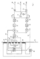
- the block diagram according to FIG. 1 contains a device, known per se, for testing metals using the eddy current method.
- This consists of an alternating current generator 10 with a switchable frequency, a test coil arrangement 12, the input 14 of which is fed by the generator 10 with an alternating current of the selected frequency, a preamplifier 18 which is connected to the output 16 of the test coil arrangement 12, one via line 20 from the generator 10 controlled phase-selective rectifier 22, the signal voltage de generated in the test coil arrangement 12 and amplified by the preamplifier 18 modulated, a filter arrangement 24 in which undesired components of the signal voltage are suppressed and a signal voltage threshold 26 which, when the signal voltage exceeds a certain threshold voltage, gives rise to a binary signal at its output 28.
- the test coil arrangement 12 has two excitation coils 30 and two receiver coils 32, each of which is passed through by the test material, a wire 34 made of non-ferromagnetic metal.
- the alternating current flowing from the generator 10 in the excitation coils 30 builds up an alternating magnetic field which penetrates the wire 34 and causes eddy currents in it. These in turn result in magnetic fields that induce 32 voltages in the receiver coils. Since the latter two are connected in series in the opposite direction of winding, the voltages induced in them stand out as long as there are no surface defects in the wire 34 to be examined. Surface defects of the wire 34 passing through the coil arrangement 12 influence the formation of the eddy currents and thus cause voltage changes in the receiver coils 32 which do not stand out because they occur at different times in the two coils. With a corresponding size of such an error, the associated signal voltage exceeds the threshold voltage in the signal voltage threshold 26, so that a binary signal is generated at its output 28.
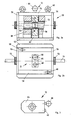
- FIGS. 2a, 2b and 3 show magnetization yoke 50 with built-in test coil arrangement 12 in a partially sectioned side view or in plan view
- FIG. 3 shows test coil arrangement 12 separately in a side view.
- the housing of the magnetization yoke 50 is composed of a base plate 52, a cover plate 54, two side plates 56 and two wall plates 58, each made of ferromagnetic material. Two support lugs 60 fastened to the cover plate 54 are used for transportation.
- an opening 62 On both sides of an opening 62 there are two magnetization coils 38 which are electrically connected in series and are connected to a direct current source 36.
- the test coil assembly 12 In the opening 62, their Continued in a recess in the cover plate 54, the test coil assembly 12 is inserted.
- the latter consists of a housing 64, a handle 66, a connecting socket 68 and a coil body 70 with four winding joints incorporated therein, in which the excitation coils 30 and the receiver coils 32 are embedded. As already described above, these are connected to one another and connected to the generator 10 or the input of the amplifier 18 via the connecting socket 68 and a cable (not shown).
- interchangeable guide nozzles 72 made of ferromagnetic material, which serve two purposes.
- they are available in different bore diameters adapted to the respective diameter of the wire 34.
- the receiver coils 32 perform an additional task.
- the ferromagnetic particles enclosed in the wire 34 and passing through the coils 32 are magnetized by the magnetic field of the magnetizing coils 38 and cause magnetic flux changes which induce a signal voltage in the coils 32.
- a simple coil 32 is sufficient for this.
- the use of two coils with the same structure, which are connected in different ways, has the advantage that voltages caused by interference fields, e.g. B. of interference fields of the supply network, stand out in the two coils 32.
- ferromagnetic particles induce 32 signal voltages of opposite polarity in the two coils at different times, which occur as a composite signal voltage at the terminals 16.
- a magnetization yoke with one or more can also be used Permanent magnets are used to generate the required constant magnetic field.
- Permanent magnets are used to generate the required constant magnetic field.
- the signal voltages at the terminals 16 of the test coil arrangement 12, that is to say both those based on eddy currents and those based on simple induction, are amplified together in the preamplifier 18.
- the output of the preamplifier 18 is connected to the input of a low-pass filter 40. This is designed so that the remainder of the carrier frequency of the generator 10 are completely suppressed in it.
- the low-pass filter 40 can be switched in its cut-off frequency.
- the changeover takes place, as indicated by a broken line 41, coupled with the changeover of the test frequency of the generator 10, so that for a selected test frequency the appropriate cutoff frequency of the low-pass filter 40 is also set at the same time.
- An amplifier 42 is connected to the output of the low-pass filter 40, and a signal voltage threshold 44 is connected to its output. If the signal voltage exceeds a predetermined amount, a binary signal is produced at the output 46 of the signal voltage threshold 44. This is to indicate that the test coil assembly 12 has been traversed by a ferromagnetic inclusion in the wire 34.
- a signal at the output 28 of the eddy current channel indicates that an inhomogeneity on the surface of the wire 34 has passed through the test coil 32. Naturally, this may also have been a particle of ferromagnetic material touching the surface of the wire 34. In contrast, a signal at the output 46 of the induction channel indicates that only a ferromagnetic particle, regardless of whether on or below the surface of the wire 34, has passed the test coil.
- the signals at the two outputs 28, 46 can be evaluated in a wide variety of ways. There can be a count of signals per Wire bundles and / or take place per unit length. Color marking of faulty spots in both categories is possible, as is the use of an acoustic or optical signaling device. In the case of the large amount of data that may arise, computer-aided data processing seems appropriate, in particular if the signals of the two outputs 28 and 46 are also to be linked.
- FIG. 1 A simple example of such a combination of the two signals is shown in FIG. 1.
- the outputs 28 and 46 are connected to the two inputs of an AND gate 74 and to an input of the AND gates 76, 78, respectively.
- a further input of the AND gate 76, 78 is connected to the output of the AND gate 74 via a negation element 80.
- There is a signal at output 82 if there is only one at output 28, i. H. if the indicated error is a pure material separation or inhomogeneity of the wire surface, not a ferromagnetic particle.
- a signal at the output 86 indicates that a signal is present only at the output 46, that is to say a ferromagnetic inclusion below the wire surface should be reported. If a signal appears at the output 84, this indicates that a ferromagnetic particle with surface contact has passed through the test coil 12. It can be seen that simply linking the signals of the eddy current and induction channels can lead to a differentiated statement about the type of error.
Landscapes
- Chemical & Material Sciences (AREA)
- Chemical Kinetics & Catalysis (AREA)
- Electrochemistry (AREA)
- Physics & Mathematics (AREA)
- Health & Medical Sciences (AREA)
- Life Sciences & Earth Sciences (AREA)
- Analytical Chemistry (AREA)
- Biochemistry (AREA)
- General Health & Medical Sciences (AREA)
- General Physics & Mathematics (AREA)
- Immunology (AREA)
- Pathology (AREA)
- Investigating Or Analyzing Materials By The Use Of Magnetic Means (AREA)
Abstract
Eine Vorrichtung zum Prüfen von langgestrecktem nicht-ferromagnetischem Prüfgut nach dem Wirbelstromverfahren wird durch zusätzliche einfache Mittel umgestaltet in eine Vorrichtung, die sowohl ein Signal über das Auftreten von Oberflächenfehlern, wie sie das Wirbelstromverfahren möglich macht, als auch ein Signal über das Vorhandensein von ferromagnetischen Teilchen im Prüfgut abgibt. Die genannten Mittel bestehen in einer Magnetisierungseinrichtung (36, 38) für das Prüfgut (34) im Bereich der Prüfspulenanordnung (12), in einer Frequenzweiche (40) zur Trennung der verschiedenen Signalspannungen und einem zusätzlichen Verarbeitungskanal (42, 44). Die Prüfspulenanordnung (12) und die Signalauswertung (74 - 86) haben beide Systeme miteinander gemeinsam. Eine sinnvolle logische Verknüpfung beider Signale wird möglich.A device for testing elongated non-ferromagnetic test material according to the eddy current method is converted by additional simple means into a device which both a signal about the occurrence of surface defects, as is made possible by the eddy current method, and a signal about the presence of ferromagnetic particles in the test material. Said means consist of a magnetization device (36, 38) for the test material (34) in the area of the test coil arrangement (12), a crossover (40) for separating the different signal voltages and an additional processing channel (42, 44). The test coil arrangement (12) and the signal evaluation (74 - 86) have both systems in common. A meaningful logical combination of both signals is possible.
Description
Die Erfindung betrifft eine Vorrichtung zum Prüfen von langgestrecktem nichtferromagnetischem metallischem Prüfgut gemäß dem Oberbegriff von Patentanspruch 1. Mit derartigen Vorrichtungen prüft man bekanntlich seit langem eine Vielfalt von Halbzeug, wie Drähte, Stangen, Rohre. Insbesondere finden solche Prüfungen statt, nachdem das Prüfgut eine formgebende Verarbeitung erfahren hat, etwa in einem Walzwerk oder dergleichen. Die Prüfung ermöglicht das Auffinden von Rissen, Lunkern, Überwalzungen, Schalen und anderen Fehlern, soweit diese sich an oder unmittelbar unter der Oberfläche des Prüfgutes befinden. Eine besondere Rolle bei den gesuchten Fehlern spielen Einschlüsse aus ferromagnetischem Material, zum einen, weil ihr Auftreten auf Mängel an den formgebenden Werkzeugen hinweist, etwa auf Verschleißerscheinungen an Walzen, deren absplitternde Teilchen in das Halbzeug eingewalzt worden sind, zum anderen, weil Einschlüsse aus ferromagnetischem Material bei der Weiterverarbeitung metallischen Halbzeuges den Anlaß zu schwerwiegenden Fehlern bilden können und insbesondere beim Ziehen des Halbzeuges auf immer kleinere Durchmesser zwangsläufig Aufspaltungen, Brüche und dergleichen verursachen, ja sogar zu Beschädigungen des Ziehwerkzeuges führen können.The invention relates to a device for testing elongated non-ferromagnetic metallic test material according to the preamble of claim 1. It is known that such devices have long been used to test a variety of semi-finished products, such as wires, rods, pipes. In particular, such tests take place after the test material has undergone shaping processing, for example in a rolling mill or the like. The test makes it possible to find cracks, cavities, overrolls, shells and other defects as far as these are located on or immediately below the surface of the test material. Inclusions made of ferromagnetic material play a special role in the sought-after defects, on the one hand because their occurrence indicates defects in the shaping tools, for example on signs of wear on rollers whose chipping particles have been rolled into the semi-finished product, and on the other hand because inclusions made of ferromagnetic Material in the further processing of metallic semifinished products can give rise to serious errors and, particularly when the semifinished product is being drawn to ever smaller diameters, inevitably cause splits, breaks and the like, and can even lead to damage to the drawing tool.
Zwei Gründe lassen die alleinige Verwendung des Wirbelstromverfahrens für die Erfassung der besagten Einschlüsse als unzureichend erscheinen. Zunächst einmal hindert der Skineffekt die Wirbelströme daran, tiefer ins Material einzudringen. Bereits ein wenig unterhalb der Oberfläche liegende Einschlüsse kommen daher nicht mehr zur Anzeige. Zwar kann man die Eindringtiefe durch Erniedrigen der Prüffrequenz etwas verbessern. Dies geht jedoch auf Kosten der Erkennbarkeit von Oberflächenfehlern und vermindert die mögliche Prüfgeschwindigkeit. Der zweite Grund beruht darauf, daß neben den bis zur Oberfläche reichenden Einschlüssen auch andere Kategorien von Oberflächenfehlern von der Wirbelstromprüfung erfaßt werden. Der Zusammenhang der Bedeutung eines Fehlers mit der zugehörigen Signalspannung ist jedoch sehr unterschiedlich, je nachdem ob es sich um Einschlüsse oder sonstige Fehler handelt. Eine eindeutige Beurteilung der Bedeutung von Fehlern ist daher nicht mehr möglich, wenn verschiedene Kategorien gleichermaßen auftreten können.There are two reasons why the sole use of the eddy current method for the detection of said inclusions appears to be insufficient. First of all, the skin effect prevents the eddy currents from penetrating deeper into the material. Inclusions already a little below the surface are therefore no longer displayed. The depth of penetration can be improved somewhat by lowering the test frequency. However, this comes at the cost of recognizing surface defects and reduces the possible testing speed. The second reason is that in addition to the inclusions reaching to the surface, other categories of surface defects are also covered by the eddy current test. The context of the meaning of a However, errors with the associated signal voltage vary widely depending on whether they are inclusions or other errors. A clear assessment of the meaning of errors is therefore no longer possible if different categories can occur equally.
Es ist ein anderes physikalisches Verfahren bekannt, mit dessen Hilfe die Ermittlung von Einschlüssen ferromagnetischen Materials in metallischem Halbzeug möglich ist. Läßt man das Halbzeug eine Spule durchlaufen, in deren Bereich ein kräftiges magnetisches Gleichfeld aufgebaut ist, so wirken die Spule durchlaufende ferromagnetische Teilchen wie ein magnetischer Dipol und induzieren in der Spule eine elektrische Spannung
V = n . d phi / dt, (1)
wobei n die Anzahl der Windungen der Spule und phi der die Spule durchdringende vom Dipol herrührende magnetische Fluß ist.Another physical method is known, with the aid of which it is possible to determine inclusions of ferromagnetic material in semifinished metal products. If the semifinished product is passed through a coil in the area of which a strong DC magnetic field is built up, ferromagnetic particles passing through the coil act like a magnetic dipole and induce an electrical voltage in the coil
V = n. d phi / dt, (1)
where n is the number of turns of the coil and phi is the magnetic flux passing through the coil and originating from the dipole.
Mit einer entsprechenden Anordnung läßt sich nun zwar sehr gut die Anwesenheit von Einschlüssen aus ferromagnetischem Material in metallischem Halbzeug nachweisen, nicht jedoch das Vorhandensein irgendwelcher anderer Oberflächenfehler, die durch das Wirbelstromverfahren leicht zu erkennen wären.With an appropriate arrangement, the presence of inclusions of ferromagnetic material in metallic semi-finished products can now be detected very well, but not the presence of any other surface defects that could be easily recognized by the eddy current method.
Es ist daher Aufgabe der Erfindung, die eingangs definierte Vorrichtung in einfacher Weise so abzuwandeln, daß mit ihrer Hilfe sowohl die Anwesenheit von Einschlüssen aus ferromagnetischem Material als auch das Vorhandensein von Oberflächenfehlern in metallischem Halbzeug nachgewiesen werden kann.It is therefore an object of the invention to modify the device defined in a simple manner so that it can be used to detect both the presence of inclusions made of ferromagnetic material and the presence of surface defects in semifinished metal products.
Diese Aufgabe wird gelöst durch eine Vorrichtung die gemäß dem Anspruch 1 gekennzeichnet ist.This object is achieved by a device which is characterized in accordance with claim 1.
Die erfindungsgemäße Lösung macht es möglich, zwei unterschiedliche physikalische Verfahren in einer gemeinsamen Vorrichtung anzuwenden, die gegenüber dem Bekannten durch nur wenige einfache Mittel ergänzt worden ist. So können insbesondere die Prüfspulenanordnung und die Mittel zum Auswerten der Signalspannungen gemeinsam für beide Verfahren benutzt werden. Als besonders vorteilhaft erweist sich die gemeinsame Verwendung nur einer Prüfspulenanordnung sowohl für das Wirbelstrom als auch für das Induktionsverfahren, wenn es um den nachträglichen Einbau in eine vorhandene Produktionslinie geht, wo aus Raumgründen das Einfügen von zwei Prüfspulenanordnungen häufig schwierig, wenn nicht unmöglich sein kann. Nach einer Ausgestaltung der Erfindung werden die ersten und zweiten Signalspannungen durch einen Tiefpaß voneinander getrennt. Nach einer anderen Ausgestaltung wird für die ersten und zweiten Signalspannungen ein gemeinsamer Vorverstärker benutzt. Eine weitere Ausgestaltung der Erfindung besteht darin, daß als Magnetisierungsmittel ein in der Wirbelstromprüftechnik gebräuchliches Magnetjoch eingesetzt wird, das sonst nur zur magnetischen Sättigung ferromagnetischer Prüfteile benutzt wird. Andere Vorteile und Ausgestaltungen der Erfindung ergeben sich aus Beschreibung und Patentansprüchen.The solution according to the invention makes it possible to use two different physical methods in a common device, which has been supplemented to the known by only a few simple means. In particular, the test coil arrangement and the means for evaluating the signal voltages can be used together for both methods. The use of only one test coil arrangement for both the eddy current and the induction process proves to be particularly advantageous when it comes to retrofitting in an existing production line, where the insertion of two test coil arrangements can often be difficult, if not impossible, for space reasons. According to one embodiment of the invention, the first and second signal voltages are separated from one another by a low-pass filter. According to another embodiment, a common preamplifier is used for the first and second signal voltages. A further embodiment of the invention consists in that a magnet yoke which is customary in eddy current testing technology is used as magnetizing means and is otherwise only used for the magnetic saturation of ferromagnetic test parts. Other advantages and refinements of the invention result from the description and the patent claims.
Im folgenden wird die Erfindung an Hand von einigen Figuren und durch ein Ausführungsbeispiel näher erläutert. Es zeigen im einzelnen:
- Figur 1 das Blockschaltbild einer Prüfvorrichtung
- Figur 2 ein Magnetisierungsjoch mit darin gehalterter Prüfspulenanordnung
- Figur 3 die Letztere gesondert.
- 1 shows the block diagram of a test device
- FIG. 2 shows a magnetization yoke with a test coil arrangement held therein
- Figure 3, the latter separately.
Im Blockschaltbild nach Figur 1 ist eine für sich allein bekannte Einrichtung zum Prüfen von Metallen nach dem Wirbelstromverfahren enthalten. Diese besteht aus einem Wechselstromgenerator 10 mit umschaltbarer Frequenz, einer Prüfspulenanordnung 12, deren Eingang 14 vom Generator 10 mit einem Wechselstrom der gewählten Frequenz gespeist wird, einem Vorverstärker 18, der an den Ausgang 16 der Prüfspulenanordnung 12 angeschlossen ist, einem über Leitung 20 vom Generator 10 gesteuerten phasenselektiven Gleichrichter 22, der die in der Prüfspulenanordnung 12 entstandene, vom Vorverstärker 18 verstärkte Signalspannung de moduliert, einer Filteranordnung 24, in der unerwünschte Bestandteile der Signalspannung unterdrückt werden und einer Signalspannungsschwelle 26, die beim Überschreiten einer bestimmten Schwellenspannung durch die Signalspannung ein binäres Signal an ihrem Ausgang 28 entstehen läßt.The block diagram according to FIG. 1 contains a device, known per se, for testing metals using the eddy current method. This consists of an
Die Prüfspulenanordnung 12 besitzt zwei Erregerspulen 30 und zwei Empfängerspulen 32, die jeweils vom Prüfgut, einem Draht 34 aus nicht-ferromagnetischem Metall durchlaufen werden. Der in den Erregerspulen 30 fließende Wechselstrom aus Generator 10 baut ein magnetisches Wechselfeld auf, das den Draht 34 durchsetzt und in ihm Wirbelströme hervorruft. Diese haben ihrerseits Magnetfelder zur Folge, die in den Empfängerspulen 32 Spannungen induzieren. Da die beiden Letzteren in entgegengesetztem Wicklungssinn hintereinander geschaltet sind, heben sich die in ihnen induzierten Spannungen solange heraus, wie sich im zu untersuchenden Draht 34 keine Oberflächenfehler befinden. Die Spulenanordnung 12 durchlaufende Oberflächenfehler des Drahtes 34 beeinflussen die Ausbildung der Wirbelströme und bewirken damit in den Empfängerspulen 32 Spannungsänderungen, die sich deshalb nicht herausheben, weil sie zu unterschiedlichen Zeiten in den beiden Spulen auftreten. Bei entsprechender Größe eines solchen Fehlers überschreitet die zugehörige Signalspannung die Schwellenspannung in der Signalspannungsschwelle 26, so daß an deren Ausgang 28 ein binäres Signal erzeugt wird.The
Den Aufbau der Prüfspulenanordnung 12 und eines zusätzlich vorgesehenen Magnetisierungsjochs 50, das gleichzeitig zur Halterung der Prüfspulenanordnung 12 dient, kann man am besten aus den Figuren 2a, 2b und 3 ersehen. Die Figuren 2a und 2b zeigen das Magnetisierungsjoch 50 mit eingebauter Prüfspulenanordnung 12 in teilweise geschnittener Seitenansicht bzw. in Draufsicht, Figur 3 zeigt die Prüfspulenanordnung 12 gesondert in einer Seitenansicht. Das Gehäuse des Magnetisierungsjochs 50 setzt sich zusammen aus einer Bodenplatte 52, einer Deckplatte 54, zwei Seitenplatten 56 und zwei Wandplatten 58, jeweils aus ferromagnetischem Werkstoff. Zwei an der Deckplatte 54 befestigte Trägösen 60 dienen der Beförderung. Beiderseits einer Öffnung 62 befinden sich zwei Magnetisierungsspulen 38, die elektrisch in Serie geschaltet sind und an eine Gleichstromquelle 36 angeschlossen sind. In die Öffnung 62, die ihre Fortsetzung in einer Aussparung der Deckplatte 54 findet, ist die Prüfspulenanordnung 12 eingesteckt. Die Letztere besteht aus einem Gehäuse 64, einem Griff 66, einer Anschlußbuchse 68 und einem Spulenkörper 70 mit vier darin eingearbeiteten Wickelfugen, in die die Erregerspulen 30 und die Empfängerspulen 32 gebettet sind. Diese sind, wie schon oben dargestellt untereinander verbunden und über die Anschlußbuchse 68 und ein nicht abgebildetes Kabel an den Generator 10 bzw. den Eingang des Verstärkers 18 angeschlossen. In den Durchlaßöffnungen der Spulen 38 stecken auswechselbare Führungsdüsen 72 aus ferromagnetischem Werkstoff, die zwei Aufgaben dienen. Zum einen sollen sie den zu prüfenden Draht 34, wie schon der Name sagt, führen und so die Bohrung des Spulenkörpers 70 vor Verschleiß und Beschädigung schützen. Sie sind zu diesem Zweck in verschiedenen, dem jeweiligen Durchmesser des Drahtes 34 angepaßten Bohrungsdurchmessern erhältlich. Zum anderen leiten sie den vom Magnetfeld der Spulen 38 herrührenden Magnetfluß in Verbindung mit den ferromagnetischen Platten 52 bis 58 optimal in den Bereich der Spulen 32.The structure of the
Die Empfängerspulen 32 übernehmen neben ihrer oben beschriebenen Zweckbestimmung als Wirbelstromspulen eine zusätzliche Aufgabe. Die im Draht 34 eingeschlossenen, die Spulen 32 durchlaufenden ferromagnetischen Teilchen werden vom Magnetfeld der Magnetisierungsspulen 38 magnetisiert und rufen Magnetflußänderungen hervor, die in den Spulen 32 eine Signalspannung induzieren. Grundsätzlich genügt dazu eine einfache Spule 32. Die Verwendung zweier in Differenz geschalteter gleich aufgebauter Spulen erbringt den Vorteil, daß von Störfeldern hervorgerufene Spannungen, z. B. von Störfeldern des Versorgungsnetzes, sich in den beiden Spulen 32 herausheben. Ferromagnetische Teilchen induzieren, in Analogie zu den von Oberflächenfehlern verursachten Wirbelstromsignalspannungen, zu unterschiedlichen Zeiten in den beiden Spulen 32 Signalspannungen entgegengesetzter Polarität, die als zusammengesetzte Signalspannung an den Klemmen 16 auftreten.In addition to their intended use as eddy current coils, the
Anstelle des im vorliegenden Beispiel beschriebenen Magnetisierungsjoches 50 mit den zwei Magnetisierungsspulen 38 und der Gleichstromquelle 36 kann ebenso ein Magnetisierungsjoch mit einem oder mehreren Permanentmagneten zur Erzeugung des erforderlichen magnetischen Gleichfeldes eingesetzt werden. Man kann dabei in vorteilhafter Weise von solchen Magnetisierungsjochen Gebrauch machen, die wie Magnetjoch 50 in der Wirbelstromprüftechnik zur magnetischen Sättigung ferromagnetischer Prüfteile vorgesehen sind, wenn es darum geht, durch magnetische Sättigung den Einfluß der magnetischen Permeabilität auszuschalten.Instead of the
Die Signalspannungen an den Klemmen 16 der Prüfspulenanordnung 12, also sowohl die auf Wirbelströmen als auch die auf einfacher Induktion beruhenden, werden im Vorverstärker 18 gemeinsam verstärkt. Der Ausgang des Vorverstärkers 18 ist mit dem Eingang eines Tiefpaßfilters 40 verbunden. Dieses ist so ausgelegt, daß in ihm die Reste der Trägerfrequenz des Generators 10 vollständig unterdrückt werden. Dazu ist das Tiefpaßfilter 40 in seiner Grenzfrequenz umschaltbar. Die Umschaltung erfolgt, wie durch eine gestrichelte Linie 41 angedeutet, gekoppelt mit der Umschaltung der Prüffrequenz des Generators 10, so daß für eine gewählte Prüffrequenz auch gleichzeitig die dazu passende Grenzfrequenz des Tiefpaßfilters 40 eingestellt ist. An den Ausgang des Tiefpaßfilters 40 ist ein Verstärker 42 angeschlossen, an dessen Ausgang wiederum eine Signalspannungsschwelle 44. Überschreitet die Signalspannung einen vorgegebenen Betrag, so entsteht am Ausgang 46 der Signalspannungsschwelle 44 ein binäres Signal. Dieses soll anzeigen, daß die Prüfspulenanordnung 12 von einem ferromagnetischen Einschluß im Draht 34 durchlaufen worden ist.The signal voltages at the
Ein Signal am Ausgang 28 des Wirbelstromkanales sagt aus, daß eine Inhomogenität an der Oberfläche des Drahtes 34 die Prüfspule 32 durchlaufen hat. Dies kann naturgemäß auch ein die Oberfläche des Drahtes 34 berührendes Teilchen aus ferromagnetischem Werkstoff gewesen sein. Dem gegenüber bekundet ein Signal am Ausgang 46 des Induktionskanales, daß ausschließlich ein ferromagnetisches Teilchen, gleichgültig ob an oder unter der Oberfläche des Drahtes 34, die Prüfspule passiert hat. Die Signale an den beiden Ausgängen 28, 46 können auf die verschiedenste Weise ausgewertet werden. Es kann eine Zählung der Signale pro Drahtbündel und/oder pro Längeneinheit stattfinden. Eine Farbmarkierung fehlerhafter Stellen beider Kategorien ist möglich, ebenso der Einsatz einer akustischen oder optischen Meldeeinrichtung. Bei der möglicherweise anfallenden großen Menge von Daten erscheint eine rechnergestützte Datenverarbeitung angebracht, insbesondere wenn es auch um die Verknüpfung der Signale der beiden Ausgänge 28 und 46 geht.A signal at the
Ein einfaches Beispiel für eine solche Verknüpfung beider Signale ist in Figur 1 dargestellt. Die Ausgänge 28 und 46 sind mit den beiden Eingängen eines Und-Gatters 74 sowie mit jeweils einem Eingang der Und-Gatter 76, 78 verbunden. Jeweils ein weiterer Eingang der bei Und-Gatter 76, 78 ist über ein Negierglied 80 an den Ausgang des Und-Gatters 74 angeschlossen. Damit ergeben sich drei weitere Ausgänge 82, 84, 86. Am Ausgang 82 steht ein Signal, wenn ein solches ausschließlich am Ausgang 28 vorliegt, d. h. wenn der angezeigte Fehler in einer reinen Materialtrennung oder Inhomogenität der Drahtoberfläche, nicht in einem ferromagnetischen Teilchen besteht. Ein Signal am Ausgang 86 zeigt an, daß ausschließlich am Ausgang 46 ein Signal vorliegt, daß also ein ferromagnetischer Einschluß unterhalb der Drahtoberfläche gemeldet werden soll. Erscheint am Ausgang 84 ein Signal, so sagt dieses aus, daß ein ferromagnetisches Teilchen mit Oberflächenberührung die Prüfspule 12 durchlaufen hat. Es zeigt sich also, daß bereits eine ganz einfache Verknüpfung der Signale des Wirbelstrom- und des Induktionskanals zu einer differenzierten Aussage über die Fehlerart führen kann.A simple example of such a combination of the two signals is shown in FIG. 1. The
Claims (8)
zusätzliche Magnetisierungsmittel (36, 38), die den sich innerhalb der Prüfspulenanordnung (12) befindlichen Bereich des Prüfgutes (34) einer kräftigen konstanten Gleichfeldmagnetisierung unterwerfen, durch eine gleichfalls an den Ausgang (16) der Prüfspulenanordnung (12) geschaltete Frequenzweiche (40), die von den oben genannten ersten Signalspannungen solche zweite Signalspannungen abtrennt, die von die Prüfspulenanordnung (12) durchlaufenden magnetisierten ferromagnetischen Teilchen hervorgerufen worden sind und durch der Frequenzweiche (40) nachgeschaltete zweite Mittel (42, 44) zum Verarbeiten der zweiten Signalspannungen.1) Device for testing elongated non-ferromagnetic metallic test material (34), with a test coil arrangement (12) comprising the test material (34) for generating eddy currents in the test material (34) and for receiving first signal voltages which are caused by the effects of the Eddy currents arise on the test coil arrangement (12) in the latter, with an alternating current generator (10) which feeds the input (14) of the test coil arrangement (12) with an alternating current causing the eddy currents and with the output (16) of the test coil arrangement (12) switched first means (18-26) for processing and evaluating said first signal voltages, characterized by
additional magnetization means (36, 38), which subject the area of the test material (34) located within the test coil arrangement (12) to strong constant DC field magnetization, by means of a crossover network (40) also connected to the output (16) of the test coil arrangement (12), which separates from the above-mentioned first signal voltages those second signal voltages which have been caused by magnetized ferromagnetic particles passing through the test coil arrangement (12) and second means (42, 44) connected downstream of the crossover network (40) for processing the second signal voltages.
daß die Prüfspulenanordnung (12) zwei in Durchlaufrichtung beabstandete Empfängerspulen (32) aufweist, die in Differenz geschaltet sind.2) Device according to claim 1, characterized in
that the test coil arrangement (12) has two receiver coils (32) which are spaced apart in the direction of passage and which are connected in difference.
daß als Frequenzweiche ein Tiefpaßfilter (40) dient, das vor die zweiten Mittel (42, 44) zum Verarbeiten und Auswerten der zweiten Signalspannungen geschaltet ist.3) Device according to claim 1 or 2, characterized in
that a low-pass filter (40) is used as the crossover, which is connected upstream of the second means (42, 44) for processing and evaluating the second signal voltages.
daß die Frequenz des Wechselstromgenerators (10) und die Grenzfrequenz des Tiefpaßfilters (40) einstellbar sind und daß die Einstellung der beiden Frequenzen durch ein gemeinsames Einstellorgan (41) erfolgt.4) Device according to claim 3, characterized in
that the frequency of the alternator (10) and the cut-off frequency of the low-pass filter (40) are adjustable and that the setting of the two frequencies is carried out by a common setting member (41).
daß die ersten und zweiten Signalspannungen einen gemeinsamen Vorverstärker (18) durchlaufen.5) Device according to one of the preceding claims, characterized in
that the first and second signal voltages pass through a common preamplifier (18).
daß als Magnetisierungsmittel ein in der Wirbelstromprüftechnik gebräuchliches Magnetjoch (50) eingesetzt wird, das sonst nur zur magnetischen Sättigung ferromagnetischer Prüfteile benutzt wird.6) Device according to one of the preceding claims, characterized in
that a magnet yoke (50) used in eddy current testing technology is used as magnetizing means, which is otherwise only used for the magnetic saturation of ferromagnetic test parts.
daß die Magnetisierungsmittel in einem Magnetjoch mit einem oder mehreren Permanentmagneten bestehen.7) Device according to one of the preceding claims, characterized in that
that the magnetizing means consist in a magnetic yoke with one or more permanent magnets.
daß von den ersten und zweiten Signalspannungen in Schwellwertstufen (26, 44) beim Überschreiten einer Spannungsschwelle erste und zweite Signale abgeleitet werden, die durch Verknüpfungsglieder (74 - 80) miteinander logisch verknüpft werden.8) Device according to one of the preceding claims, characterized in that
that first and second signals are derived from the first and second signal voltages in threshold value stages (26, 44) when a voltage threshold is exceeded, which signals are logically linked to one another by logic elements (74-80).
Applications Claiming Priority (2)
| Application Number | Priority Date | Filing Date | Title |
|---|---|---|---|
| DE19873743521 DE3743521A1 (en) | 1987-12-22 | 1987-12-22 | DEVICE FOR TESTING SEMI-PRODUCTS |
| DE3743521 | 1987-12-22 |
Publications (3)
| Publication Number | Publication Date |
|---|---|
| EP0322552A2 true EP0322552A2 (en) | 1989-07-05 |
| EP0322552A3 EP0322552A3 (en) | 1990-10-10 |
| EP0322552B1 EP0322552B1 (en) | 1995-05-17 |
Family
ID=6343260
Family Applications (1)
| Application Number | Title | Priority Date | Filing Date |
|---|---|---|---|
| EP88119186A Expired - Lifetime EP0322552B1 (en) | 1987-12-22 | 1988-11-18 | Apparatus for testing semi-products |
Country Status (4)
| Country | Link |
|---|---|
| US (1) | US4954777A (en) |
| EP (1) | EP0322552B1 (en) |
| JP (1) | JPH01203965A (en) |
| DE (2) | DE3743521A1 (en) |
Cited By (1)
| Publication number | Priority date | Publication date | Assignee | Title |
|---|---|---|---|---|
| CN119619280A (en) * | 2024-11-21 | 2025-03-14 | 华中科技大学 | Pulse eddy current detection imaging method and system for ferromagnetic components |
Families Citing this family (39)
| Publication number | Priority date | Publication date | Assignee | Title |
|---|---|---|---|---|
| DE3909729A1 (en) * | 1989-03-23 | 1990-09-27 | Gerald Schiebold | VARIABLE HYBRID PROBE FOR MEASURING AND TESTING PURPOSES AND FOR SCANING SURFACES IN DESTRUCTION-FREE MATERIAL TESTING, EVEN IN STRONG GENERAL MAGNETIC OVERLAYER / INTERFERENCE FIELDS |
| JP2767278B2 (en) * | 1989-04-10 | 1998-06-18 | 株式会社日本コンラックス | Coin sorting equipment |
| DE3937261C2 (en) * | 1989-11-09 | 1996-04-11 | Foerster Inst Dr Friedrich | Rotating head for scanning metallic test material |
| FR2660068B1 (en) * | 1990-03-26 | 1993-12-03 | Vallourec Industries | METHOD AND DEVICE FOR MONITORING METAL TUBES BY EDGE CURRENT. |
| US5491409A (en) * | 1992-11-09 | 1996-02-13 | The Babcock & Wilcox Company | Multiple yoke eddy current technique for detection of surface defects on metal components covered with marine growth |
| US5442285A (en) * | 1994-02-28 | 1995-08-15 | Westinghouse Electric Corporation | NDE eddy current sensor for very high scan rate applications in an operating combustion turbine |
| JP2768906B2 (en) * | 1994-07-27 | 1998-06-25 | 株式会社神代鉄工所 | Adjustment method of foreign object detection coil device of transport sorting machine and transport sorting machine |
| JPH0854375A (en) * | 1994-08-11 | 1996-02-27 | Kaisei Enjinia Kk | Electromagnetic induction-type inspecting apparatus |
| US6249119B1 (en) * | 1998-10-07 | 2001-06-19 | Ico, Inc. | Rotating electromagnetic field defect detection system for tubular goods |
| US7295003B2 (en) * | 2004-09-22 | 2007-11-13 | The Boeing Company | Non-destructive testing system and method utilizing a magnetic field to identify defects in a layer of a laminated material |
| CN101563033B (en) * | 2006-12-20 | 2013-05-29 | 皇家飞利浦电子股份有限公司 | Device and method for influencing and/or detecting magnetic particles in a region of action |
| US9823090B2 (en) | 2014-10-31 | 2017-11-21 | Allegro Microsystems, Llc | Magnetic field sensor for sensing a movement of a target object |
| DE102008053778B4 (en) * | 2008-10-23 | 2020-08-06 | Institut Dr. Foerster Gmbh & Co. Kg | Test method and test device for testing elongated objects by means of a through coil |
| JP4766472B1 (en) * | 2010-10-22 | 2011-09-07 | 国立大学法人 岡山大学 | Nondestructive inspection apparatus and nondestructive inspection method |
| US9817078B2 (en) | 2012-05-10 | 2017-11-14 | Allegro Microsystems Llc | Methods and apparatus for magnetic sensor having integrated coil |
| US10495699B2 (en) * | 2013-07-19 | 2019-12-03 | Allegro Microsystems, Llc | Methods and apparatus for magnetic sensor having an integrated coil or magnet to detect a non-ferromagnetic target |
| US9823092B2 (en) | 2014-10-31 | 2017-11-21 | Allegro Microsystems, Llc | Magnetic field sensor providing a movement detector |
| US9719806B2 (en) | 2014-10-31 | 2017-08-01 | Allegro Microsystems, Llc | Magnetic field sensor for sensing a movement of a ferromagnetic target object |
| US9720054B2 (en) | 2014-10-31 | 2017-08-01 | Allegro Microsystems, Llc | Magnetic field sensor and electronic circuit that pass amplifier current through a magnetoresistance element |
| US10712403B2 (en) | 2014-10-31 | 2020-07-14 | Allegro Microsystems, Llc | Magnetic field sensor and electronic circuit that pass amplifier current through a magnetoresistance element |
| US10012518B2 (en) | 2016-06-08 | 2018-07-03 | Allegro Microsystems, Llc | Magnetic field sensor for sensing a proximity of an object |
| US10837943B2 (en) | 2017-05-26 | 2020-11-17 | Allegro Microsystems, Llc | Magnetic field sensor with error calculation |
| US10996289B2 (en) | 2017-05-26 | 2021-05-04 | Allegro Microsystems, Llc | Coil actuated position sensor with reflected magnetic field |
| US10324141B2 (en) | 2017-05-26 | 2019-06-18 | Allegro Microsystems, Llc | Packages for coil actuated position sensors |
| US10641842B2 (en) | 2017-05-26 | 2020-05-05 | Allegro Microsystems, Llc | Targets for coil actuated position sensors |
| US11428755B2 (en) | 2017-05-26 | 2022-08-30 | Allegro Microsystems, Llc | Coil actuated sensor with sensitivity detection |
| US10310028B2 (en) | 2017-05-26 | 2019-06-04 | Allegro Microsystems, Llc | Coil actuated pressure sensor |
| JP6452880B1 (en) * | 2018-06-13 | 2019-01-16 | 東亜非破壊検査株式会社 | Method and apparatus for inspecting flaws or defects in tubular body |
| US11255700B2 (en) | 2018-08-06 | 2022-02-22 | Allegro Microsystems, Llc | Magnetic field sensor |
| US10823586B2 (en) | 2018-12-26 | 2020-11-03 | Allegro Microsystems, Llc | Magnetic field sensor having unequally spaced magnetic field sensing elements |
| US11061084B2 (en) | 2019-03-07 | 2021-07-13 | Allegro Microsystems, Llc | Coil actuated pressure sensor and deflectable substrate |
| US10955306B2 (en) | 2019-04-22 | 2021-03-23 | Allegro Microsystems, Llc | Coil actuated pressure sensor and deformable substrate |
| US11237020B2 (en) | 2019-11-14 | 2022-02-01 | Allegro Microsystems, Llc | Magnetic field sensor having two rows of magnetic field sensing elements for measuring an angle of rotation of a magnet |
| US11280637B2 (en) | 2019-11-14 | 2022-03-22 | Allegro Microsystems, Llc | High performance magnetic angle sensor |
| US11262422B2 (en) | 2020-05-08 | 2022-03-01 | Allegro Microsystems, Llc | Stray-field-immune coil-activated position sensor |
| JP7559594B2 (en) * | 2021-02-12 | 2024-10-02 | 株式会社プロテリアル | Quality evaluation method and manufacturing method |
| US11493361B2 (en) | 2021-02-26 | 2022-11-08 | Allegro Microsystems, Llc | Stray field immune coil-activated sensor |
| US11578997B1 (en) | 2021-08-24 | 2023-02-14 | Allegro Microsystems, Llc | Angle sensor using eddy currents |
| US12523717B2 (en) | 2024-02-15 | 2026-01-13 | Allegro Microsystems, Llc | Closed loop magnetic field sensor with current control |
Family Cites Families (18)
| Publication number | Priority date | Publication date | Assignee | Title |
|---|---|---|---|---|
| US2207592A (en) * | 1938-03-28 | 1940-07-09 | Gen Electric | Detecting magnetic particles in nonmagnetic materials |
| US3065412A (en) * | 1958-12-23 | 1962-11-20 | Union Carbide Corp | Metal detector |
| US3271664A (en) * | 1961-12-04 | 1966-09-06 | Magnaflux Corp | Combined leakage field and eddy current detection system |
| US3401332A (en) * | 1963-11-12 | 1968-09-10 | Magnaflux Corp | Magnetic leakage field and eddy current flaw detection system |
| US3314006A (en) * | 1965-04-19 | 1967-04-11 | Automation Forster Inc | Variable frequency eddy current test device with variable means for maintaining the apparent impedance of the probe constant at all frequencies |
| US3391336A (en) * | 1965-10-20 | 1968-07-02 | Automation Forster Inc | Eddy current nondestructive testing apparatus having adjustable output signal conversion means |
| US3538433A (en) * | 1968-07-15 | 1970-11-03 | American Mach & Foundry | Apparatus for discriminating between inside and outside defects using a combined leakage field and eddy current test system |
| JPS4890287A (en) * | 1972-02-29 | 1973-11-24 | ||
| US3972156A (en) * | 1975-02-24 | 1976-08-03 | Sperry Rand Corporation | Speed-independent static magnetic field metal detector |
| US4095180A (en) * | 1975-12-29 | 1978-06-13 | K. J. Law Engineers, Inc. | Method and apparatus for testing conductivity using eddy currents |
| US4383218A (en) * | 1978-12-29 | 1983-05-10 | The Boeing Company | Eddy current flow detection including compensation for system variables such as lift-off |
| US4303885A (en) * | 1979-06-18 | 1981-12-01 | Electric Power Research Institute, Inc. | Digitally controlled multifrequency eddy current test apparatus and method |
| US4602212A (en) * | 1982-06-14 | 1986-07-22 | Sumitomo Metal Industries, Ltd. | Method and apparatus including a flux leakage and eddy current sensor for detecting surface flaws in metal products |
| DE3236224C2 (en) * | 1982-09-30 | 1985-03-28 | Werner Turck Gmbh & Co Kg, 5884 Halver | Inductive proximity switch |
| JPS60247155A (en) * | 1984-05-22 | 1985-12-06 | Sumitomo Metal Ind Ltd | Method and apparatus for measuring particle size of crystal |
| JPS61277051A (en) * | 1985-05-31 | 1986-12-08 | Sumitomo Metal Ind Ltd | Apparatus for measuring magnetic characteristics |
| DE3530525C2 (en) * | 1985-08-27 | 1994-05-11 | Foerster Inst Dr Friedrich | Device for non-destructive material testing |
| JPH0654306B2 (en) * | 1985-11-06 | 1994-07-20 | 住友金属工業株式会社 | Crystal grain size measuring method and apparatus |
-
1987
- 1987-12-22 DE DE19873743521 patent/DE3743521A1/en active Granted
-
1988
- 1988-11-18 EP EP88119186A patent/EP0322552B1/en not_active Expired - Lifetime
- 1988-11-18 DE DE3853812T patent/DE3853812D1/en not_active Expired - Fee Related
- 1988-12-09 US US07/282,450 patent/US4954777A/en not_active Expired - Fee Related
- 1988-12-21 JP JP63320791A patent/JPH01203965A/en active Pending
Cited By (1)
| Publication number | Priority date | Publication date | Assignee | Title |
|---|---|---|---|---|
| CN119619280A (en) * | 2024-11-21 | 2025-03-14 | 华中科技大学 | Pulse eddy current detection imaging method and system for ferromagnetic components |
Also Published As
| Publication number | Publication date |
|---|---|
| EP0322552A3 (en) | 1990-10-10 |
| US4954777A (en) | 1990-09-04 |
| DE3853812D1 (en) | 1995-06-22 |
| DE3743521A1 (en) | 1989-07-06 |
| JPH01203965A (en) | 1989-08-16 |
| DE3743521C2 (en) | 1992-07-30 |
| EP0322552B1 (en) | 1995-05-17 |
Similar Documents
| Publication | Publication Date | Title |
|---|---|---|
| EP0322552B1 (en) | Apparatus for testing semi-products | |
| DE3240964C2 (en) | ||
| EP0467202B1 (en) | Arrangement for testing of objects with magnetic properties | |
| DE69605330T2 (en) | Device for induction borehole measurement in the presence of metallic walls | |
| DE2928899C2 (en) | Device for determining the size and direction of the lateral deviation of a test head from the center line of a weld seam | |
| WO2011154088A1 (en) | Method and apparatus for checking value documents | |
| DE1932462A1 (en) | Method and device for testing pipelines | |
| DE1516589A1 (en) | Method and device for detecting the passage of a moving object | |
| DE3527819A1 (en) | METHOD AND DEVICE FOR LOCATING CRACKS IN CONVEYOR STRANDS | |
| EP0039019B1 (en) | Equipment for the continuous contactless control of the structural condition of a cold-drawn band | |
| DE3001885A1 (en) | TEST DEVICE FOR DESTRUCTION-FREE MATERIAL TESTING ON FAULTS | |
| DE3212465A1 (en) | TRANSPORT DEVICE, ESPECIALLY LOADING DEVICE FOR MACHINING MACHINES | |
| WO2023275372A1 (en) | Sensor device and method for characterizing metal chips | |
| DE3114247C2 (en) | Method for the non-destructive testing of a workpiece made of electrically conductive material | |
| DE2526978A1 (en) | METHOD AND DEVICE FOR MEASURING MAGNETIC ANOMALIES IN FERROMAGNETIC AND NON-FERROMAGNETIC MATERIALS | |
| EP3874475B1 (en) | Magnetic testing of valuable documents | |
| DE112005000106B4 (en) | Electromagnetic-acoustic transducer | |
| DE1573837A1 (en) | Magnetic testing device | |
| EP0442267B1 (en) | Method and apparatus for testing with magnetic powder | |
| DE102015122812A1 (en) | Magnetizing arrangement, magnetizing device and method for magnetizing a built-in workpiece made of hard magnetic material | |
| DE322252C (en) | Method for increasing the sensitivity, especially of those magnetic instruments and apparatus, whose effect depends on the permeability of soft iron or similar magnetic material | |
| DE3709934A1 (en) | MAGNETIZING DEVICE FOR MAGNETOGRAPHIC CHECKING OF WORKPIECES | |
| DE1489214B2 (en) | METHOD FOR MAGNETIC MARKING OF MAGNETIZABLE LONG ELEVATED BODIES AND FOR REACHING THE MARKING AND DEVICES FOR CARRYING OUT THE METHOD | |
| EP3931576B1 (en) | Device and method for determining the speed or acceleration of an electrically conductive object, and system | |
| DE2411565A1 (en) | Apparatus to test ferromagnetic strips magnetically - has coil to magnetise strip when excited combined with yokes forming closed magnetic circuit |
Legal Events
| Date | Code | Title | Description |
|---|---|---|---|
| PUAI | Public reference made under article 153(3) epc to a published international application that has entered the european phase |
Free format text: ORIGINAL CODE: 0009012 |
|
| AK | Designated contracting states |
Kind code of ref document: A2 Designated state(s): DE FR GB IT SE |
|
| PUAL | Search report despatched |
Free format text: ORIGINAL CODE: 0009013 |
|
| AK | Designated contracting states |
Kind code of ref document: A3 Designated state(s): DE FR GB IT SE |
|
| 17P | Request for examination filed |
Effective date: 19900827 |
|
| 17Q | First examination report despatched |
Effective date: 19920715 |
|
| 18D | Application deemed to be withdrawn |
Effective date: 19921126 |
|
| 18RA | Request filed for re-establishment of rights before grant |
Effective date: 19930629 |
|
| D18Z | Request filed for re-establishment of rights before grant (deleted) | ||
| D18D | Application deemed to be withdrawn (deleted) | ||
| GRAA | (expected) grant |
Free format text: ORIGINAL CODE: 0009210 |
|
| AK | Designated contracting states |
Kind code of ref document: B1 Designated state(s): DE FR GB IT SE |
|
| PG25 | Lapsed in a contracting state [announced via postgrant information from national office to epo] |
Ref country code: IT Free format text: LAPSE BECAUSE OF FAILURE TO SUBMIT A TRANSLATION OF THE DESCRIPTION OR TO PAY THE FEE WITHIN THE PRE;WARNING: LAPSES OF ITALIAN PATENTS WITH EFFECTIVE DATE BEFORE 2007 MAY HAVE OCCURRED AT ANY TIME BEFORE 2007. THE CORRECT EFFECTIVE DATE MAY BE DIFFERENT FROM THE ONE RECORDED.SCRIBED TIME-LIMIT Effective date: 19950517 |
|
| REF | Corresponds to: |
Ref document number: 3853812 Country of ref document: DE Date of ref document: 19950622 |
|
| ET | Fr: translation filed | ||
| GBT | Gb: translation of ep patent filed (gb section 77(6)(a)/1977) |
Effective date: 19950712 |
|
| PG25 | Lapsed in a contracting state [announced via postgrant information from national office to epo] |
Ref country code: SE Effective date: 19950817 |
|
| PLBE | No opposition filed within time limit |
Free format text: ORIGINAL CODE: 0009261 |
|
| STAA | Information on the status of an ep patent application or granted ep patent |
Free format text: STATUS: NO OPPOSITION FILED WITHIN TIME LIMIT |
|
| 26N | No opposition filed | ||
| PGFP | Annual fee paid to national office [announced via postgrant information from national office to epo] |
Ref country code: GB Payment date: 19991028 Year of fee payment: 12 |
|
| PGFP | Annual fee paid to national office [announced via postgrant information from national office to epo] |
Ref country code: FR Payment date: 19991116 Year of fee payment: 12 |
|
| PGFP | Annual fee paid to national office [announced via postgrant information from national office to epo] |
Ref country code: DE Payment date: 19991227 Year of fee payment: 12 |
|
| PG25 | Lapsed in a contracting state [announced via postgrant information from national office to epo] |
Ref country code: GB Free format text: LAPSE BECAUSE OF NON-PAYMENT OF DUE FEES Effective date: 20001118 |
|
| GBPC | Gb: european patent ceased through non-payment of renewal fee |
Effective date: 20001118 |
|
| PG25 | Lapsed in a contracting state [announced via postgrant information from national office to epo] |
Ref country code: FR Free format text: LAPSE BECAUSE OF NON-PAYMENT OF DUE FEES Effective date: 20010731 |
|
| PG25 | Lapsed in a contracting state [announced via postgrant information from national office to epo] |
Ref country code: DE Free format text: LAPSE BECAUSE OF NON-PAYMENT OF DUE FEES Effective date: 20010801 |
|
| REG | Reference to a national code |
Ref country code: FR Ref legal event code: ST |