EP0322497A2 - Plasticising aggregate for a plastic injection-moulding machine - Google Patents
Plasticising aggregate for a plastic injection-moulding machine Download PDFInfo
- Publication number
- EP0322497A2 EP0322497A2 EP88102692A EP88102692A EP0322497A2 EP 0322497 A2 EP0322497 A2 EP 0322497A2 EP 88102692 A EP88102692 A EP 88102692A EP 88102692 A EP88102692 A EP 88102692A EP 0322497 A2 EP0322497 A2 EP 0322497A2
- Authority
- EP
- European Patent Office
- Prior art keywords
- nozzle
- plasticizing
- cylinder
- unit according
- bore
- Prior art date
- Legal status (The legal status is an assumption and is not a legal conclusion. Google has not performed a legal analysis and makes no representation as to the accuracy of the status listed.)
- Granted
Links
Images


Classifications
-
- B—PERFORMING OPERATIONS; TRANSPORTING
- B29—WORKING OF PLASTICS; WORKING OF SUBSTANCES IN A PLASTIC STATE IN GENERAL
- B29C—SHAPING OR JOINING OF PLASTICS; SHAPING OF MATERIAL IN A PLASTIC STATE, NOT OTHERWISE PROVIDED FOR; AFTER-TREATMENT OF THE SHAPED PRODUCTS, e.g. REPAIRING
- B29C45/00—Injection moulding, i.e. forcing the required volume of moulding material through a nozzle into a closed mould; Apparatus therefor
- B29C45/17—Component parts, details or accessories; Auxiliary operations
- B29C45/20—Injection nozzles
- B29C45/23—Feed stopping equipment
- B29C45/231—Needle valve systems therefor
-
- B—PERFORMING OPERATIONS; TRANSPORTING
- B29—WORKING OF PLASTICS; WORKING OF SUBSTANCES IN A PLASTIC STATE IN GENERAL
- B29C—SHAPING OR JOINING OF PLASTICS; SHAPING OF MATERIAL IN A PLASTIC STATE, NOT OTHERWISE PROVIDED FOR; AFTER-TREATMENT OF THE SHAPED PRODUCTS, e.g. REPAIRING
- B29C45/00—Injection moulding, i.e. forcing the required volume of moulding material through a nozzle into a closed mould; Apparatus therefor
- B29C45/17—Component parts, details or accessories; Auxiliary operations
- B29C45/20—Injection nozzles
- B29C45/23—Feed stopping equipment
- B29C2045/235—Feed stopping equipment axially movable inclined or orthogonal valves
Definitions
- the invention relates to a plasticizing unit according to the preamble of claim 1.
- the nozzle needle is arranged coaxially to the nozzle body of the closure nozzle and can be actuated by the control cylinder via a two-armed lever (FR-PS 1.439.001 Fig. 7.8; DE-GM 7 020 969 Fig. 5-7).
- a two-armed lever When actuated via a two-armed lever, the nozzle channel is not coaxial with the spray axis. Rather, the plasticized plastic passes from the plasticizing space of the plasticizing cylinder into the mouth area of the closure nozzle via bypass channels which are offset radially to the spray axis.
- bypass channels which are offset radially to the spray axis.
- sealing nozzles the spring-loaded nozzle needle of which is arranged at an angle to the spray nozzle in the nozzle body
- FR-PS 1.439.001 Fig. 3 magazine “Kunststoffe” Vol.49-1959, Issue 4, S.199-200.
- the nozzle needle opens when a certain limit pressure is exceeded in the plastic material.
- such closure nozzles lack the prerequisites for control according to a computer program.
- the invention has for its object to develop a plasticizing unit of the type mentioned in such a way that an unimpeded flow of the plastic material through the closure nozzle is possible and thus the pressure drop in the closure nozzle, which is usually to be noted, is largely avoidable, which therefore has all the advantageous properties of an 'open' nozzle has and can be used as such when the valve pin is in a permanent open position.
- An “open” nozzle in the above sense is understood to mean a nozzle whose nozzle body has a nozzle channel coaxial with the spray axis and is without closure elements.
- Open nozzles of this type work in conjunction with a decompression device, which frees the plastic material in the plasticizing cylinder from the injection mold from the injection mold before the plasticizing unit is set down, by means of a corresponding axial return stroke of the screw conveyor. This prevents undesired leakage of the plastic material from the nozzle.
- Such open nozzles are widely used thanks to their versatility when processing different plastics and because of their low susceptibility to faults.
- sealing nozzles are indispensable when dealing with special injection molding tasks, for example when processing polyamides. They make one possible high injection speed in the initial phase of injection, when the plastic material in the plasticizing cylinder is under a corresponding overpressure before the nozzle is opened.
- connection between the nozzle body and the plasticizing cylinder after removal of the sealing nozzle e.g. for the purpose of changing or repairing, can be restored again in such a way that the nozzle needle always has the same angle to the horizontal ( ⁇ in FIG. 9).
- This angle is exactly adjustable in a design according to claim 7, so that tension in the force-transmitting members can be avoided from the outset.
- the construction of the closure nozzle according to the invention also enables a particularly efficient series production if the nozzle needle slides directly in the sliding hole made in the nozzle body, that is, if its diameter corresponds to the clear width of the sliding hole.
- This direct guiding of the nozzle needle in the nozzle body also has the advantage that a smaller diameter nozzle needle can be used without significant weakening of the nozzle body, which in turn facilitates the control of the nozzle needle.
- the nozzle needle has a diameter of approximately 4 mm. If the control cylinder is arranged parallel to the spray axis, a force deflection onto the nozzle needle is possible without tension occurring in the force-transmitting members or in the nozzle needle if the force deflection takes place to a certain extent via a cardan joint system according to claims 3-5.
- the nozzle body 70 with the lateral surface 70m has a coaxial nozzle channel 70a, which extends as far as the nozzle mouth 70a ⁇ and which is completely free for the flow of the plastic material.
- the nozzle needle 73 which shuts off the nozzle channel 70a at the nozzle mouth 70a kann, is received in a sliding bore 70e running at an acute angle to the nozzle channel 70a.
- the nozzle body 70 is in one piece and provided with a flat contact surface 70 l.
- the diameter of the nozzle needle 73 corresponds to the clear width of the nozzle bore 70e through which the nozzle channel 70a is cut behind the nozzle mouth 70a ⁇ at the front end of a mouth section 70a '.
- the plasticizing cylinder 11 is provided with a radially symmetrical connection bore 11e for receiving a radial flange 70k of the nozzle body 70.
- the clear width of the connection bore 11e corresponds to the diameter of a connection thread 72a of a hollow screw 72. This is provided with a radial flange 72c with an outer edge for the engagement of a tool.
- the connection thread 72a of the hollow screw 72 is in engagement with an internal thread in the connection bore 11e.
- annular, finely ground, flat sealing surface 70 l of the radial flange 70 k can be pressed onto a corresponding sealing surface 11 a of the plasticizing cylinder 11 by the hollow screw 72 acting axially on the annular shoulder 70 h of the nozzle body 70 via the contact surface.
- Axial jamming of the radial flange 70k of the nozzle body 70 with the plasticizing cylinder takes place after this nozzle body has been adjusted in such a way that the nozzle needle 73 and the force-transmitting elements lie symmetrically to the vertical plane of symmetry zz (FIG. 9).
- the nozzle bore 70a has an inlet section 70a ′′′ narrowing in a funnel-like manner, in which the conical end is located 70a 'of the nozzle channel 70a ends in the nozzle mouth 70a ⁇ .
- a receiving bore 70g is made for the thermal sensor 78 of the nozzle body 70, which can be heated with a separate heating device.
- the heating device comprises, as can be seen in particular from FIG. 5, a heating coil 79 and a tensioning band 83, which is placed thereon and can be tensioned by means of a screw 84 and which engages with tensioning bolts 85.
- the nozzle needle 73 can be controlled both in the closed position and in the open position.
- a coil spring 26 encloses the shift rod 82, which coil spring 26 engages the shift rod via a snap ring 87 and is supported on a reinforcing element 51 of the plasticizing cylinder.
- the nozzle needle 73 which is loaded by a spring, is held in the closed position even when the selector rod 82 is uncoupled from the control cylinder 14.
- the by means of radially and vertically guided slide 33 ';33 ⁇ ; 33 ′′′ in the bore 10a of the carrier element 10 lockable plasticizing cylinder 11 can be released in the wake of a backward movement of the carrier element 10 for replacement with the screw conveyor.
- the control cylinder 14 is arranged on the carrier element 10 and forms a movement unit with this carrier element 10 during the release movement.
- the automatic coupling between the switching rod 82 and the piston rod of the control cylinder 14 comprises, as can be seen from FIG. 1, a coupling part 14b and arranged on the switching rod 82 a on the piston rod of the control cylinder 14 arranged coupling part 17.
- the coupling is arranged in a recess T of the carrier element 10.
- the shift rod 82 is guided approximately parallel to the spray axis aa in reinforcing elements 50, 52 of the plasticizing cylinder 11 by means of sliding sleeves 57.
- the plasticizing cylinder 11 provided with a heating device has a two-part protective cover 18, the lower one of which Part 18 ⁇ covers the shift rod 82 and the upper part 18 'has a retaining ring 53. Both parts are attached to the reinforcing element 51 of the plasticizing cylinder 11.
- the head of the lower fastening screw 54 is designed as a centering cone.
- the plasticizing unit When the plasticizing unit is being removed, the latter can engage in a centering manner in corresponding centering recesses in the storage surfaces of the transport devices.
- the plasticizing cylinder After a program-controlled unlocking of the plasticizing cylinder and after it has been axially locked, the plasticizing cylinder can be released from the carrier element 10 by being pulled off the plasticizing cylinder 11 by hydraulic means.
- connector 29' are separated from the connector 29 attached to a connector plate 28 of the plasticizing cylinder 29.
- the plasticizing cylinder 11 can be assigned a nozzle body 170 which is identical to the nozzle body 70 with regard to the outer shape and without a nozzle bore.
- This nozzle body 170 is interchangeable with the nozzle body 70 to form an open nozzle 0 as required.
- the optional nozzle bodies 70; 170 secured in the working position with the aid of a pin 71 which, in order to prevent rotation, dips into the nozzle body 70 at one end and into the plasticizing cylinder 11 at the other end.
- the flow channels 70a of the optional nozzle body 70 (for the sealing nozzle) or 170 (for the open nozzle 0) are arranged concentrically with the heating coil 79, so that when the optional nozzles V and 0 are controlled, the thermal conditions in the first Flow channel 70a can be assumed.
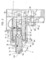
- the rear end section 77a of the actuating rod 77 extends through a recess 50a (FIG. 2) of the adjacent reinforcing element 50.
Landscapes
- Engineering & Computer Science (AREA)
- Manufacturing & Machinery (AREA)
- Mechanical Engineering (AREA)
- Injection Moulding Of Plastics Or The Like (AREA)
Abstract
Der Plastifizierzylinder des Plastifizieraggregates ist mit einer verschließbaren Düse (V) ausgerüstet, die mittels einer hydraulischen Kolben-Zylinder-Einheit (Steuerzylinder 14) steuerbar ist. Der Düsenkörper (70) der Düse (V) weist einen koaxialen, sich bis zur Düsenmündung erstreckenden und für den Durchfluß des Kunststoffmaterials freien Düsenkanal (70a) auf. Die den Düsenkanal (70a) an der Düsenmündung absperrende Düsennadel (73) ist in einer spitzwinklig zum Düsenkanal (70a) verlaufenden Schiebebohrung (70e) aufgenommen. Dadurch wird erreicht, daß ein unbehinderter Durchfluß des Kunststoffmaterials durch die Verschlußdüse möglich und dadurch der üblicherweise zu verzeichnende Druckabfall in der Verschlußdüse weitgehend vermeidbar ist. Zudem weist die verschließbare Düse (V) alle Eigenschaften einer 'offenen' Düse auf und ist als solche einsetzbar, wenn sich die Verschlußnadel (73) in permanenter Offenstellung befindet. 
Description
Die Erfindung bezieht sich auf ein Plastifizieraggregat entsprechend dem Oberbegriff des Patentanspruches 1.The invention relates to a plasticizing unit according to the preamble of claim 1.
Bei bekannten Plastifizieraggregaten dieser Art ist die Düsennadel koaxial zum Düsenkörper der Verschlußdüse angeordnet und über einen zweiarmigen Hebel (FR-PS 1.439.001 Fig. 7,8; DE-GM 7 020 969 Fig. 5-7) vom Steuerzylinder betätigbar. Bei Betätigung über einen zweiarmigen Hebel ist eine zur Spritzachse koaxialer Verlauf des Düsenkanals nicht möglich. Der plastifizierte Kunststoff gelangt vielmehr über radial zur Spritzachse versetzte Umgehungskanäle aus dem Plastifizierraum des Plastifizierzylinders in den Mündungsbereich der Verschlußdüse. Infolge mehrfacher Änderung der Strömungsrichtung des plastischen Kunststoffes ist dabei bei der Querschnittsgestaltung der Umgehungskanäle in aller Regel ein erheblicher Druckabfall zu verzeichnen. Im Falle einer Betätigung der Düsennadel durch den Steuerzylinder (DE-GM 7 020 969 Fig. 5-7) setzt diese Düsennadel unmittelbar am Kolben des Steuerzylinders an, der koaxial zum Durchflußkanal liegt. Die koaxiale Anordnung des Steuerzylinders setzt nun aber eine zur Verschlußdüse seitlich versetzte Anordnung des Plastifizierzylinders voraus. Demzufolge ist weder bei Betätigung der Düsennadel über einen Hebel noch bei ihrer unmittelbaren Betätigung durch einen koaxialen Steuerzylinder ein durchgehend linearer Durchflußkanal vom Plastifizierraum des Plastifizierzylinders zur Düsenmündung zu verwirklichen, weil der Realisierung eines solchen Düsenkanals entweder der kraftübertragende Hebel oder der Steuerzylinder als solcher im Wege steht. Insoweit sind in jedem Falle Kanäle für den Durchfluß des Kunststoffes mit quer zur Spritzachse verlaufenden Abschnitten erforderlich.In known plasticizing units of this type, the nozzle needle is arranged coaxially to the nozzle body of the closure nozzle and can be actuated by the control cylinder via a two-armed lever (FR-PS 1.439.001 Fig. 7.8; DE-GM 7 020 969 Fig. 5-7). When actuated via a two-armed lever, the nozzle channel is not coaxial with the spray axis. Rather, the plasticized plastic passes from the plasticizing space of the plasticizing cylinder into the mouth area of the closure nozzle via bypass channels which are offset radially to the spray axis. As a result of multiple changes in the direction of flow of the plastic plastic, there is generally a considerable drop in pressure in the cross-sectional design of the bypass channels. In the event of actuation of the nozzle needle by the control cylinder (DE-GM 7 020 969 Fig. 5-7), this nozzle needle attaches directly to the piston of the control cylinder, which is coaxial with the flow channel. The coaxial arrangement of the control cylinder now presupposes an arrangement of the plasticizing cylinder that is laterally offset from the sealing nozzle. Accordingly, neither when the nozzle needle is actuated by a lever nor when it is actuated directly by one coaxial control cylinder to realize a continuously linear flow channel from the plasticizing chamber of the plasticizing cylinder to the nozzle mouth, because the realization of such a nozzle channel either the force-transmitting lever or the control cylinder as such stands in the way. In this respect, channels for the flow of the plastic with sections extending transversely to the spray axis are required in any case.
Bekannt sind auch Verschlußdüsen, deren von einer Feder belastete Düsennadel winklig zur Spritzaches im Düsenkörper angeordnet ist (FR-PS 1.439.001 Fig. 3; Zeitschrift "Kunststoffe" Bd.49-1959, Heft 4, S.199-200). Bei solchen Verschlußdüsen öffnet die Düsennadel, wenn beim Kunststoffmaterial ein bestimmter Grenzdruck überschritten wird. Insoweit fehlen solchen Verschlußdüsen die Voraussetzungen für eine Steuerung nach dem Programm eines Rechners.Also known are sealing nozzles, the spring-loaded nozzle needle of which is arranged at an angle to the spray nozzle in the nozzle body (FR-PS 1.439.001 Fig. 3; magazine "Kunststoffe" Vol.49-1959, Issue 4, S.199-200). In such closure nozzles, the nozzle needle opens when a certain limit pressure is exceeded in the plastic material. To this extent, such closure nozzles lack the prerequisites for control according to a computer program.
Der Erfindung liegt die Aufgabe zugrunde, ein Plastifizieraggregat der eingangs genannten Gattung derart weiterzubilden, daß ein unbehinderter Durchfluß des Kunststoffmaterials durch die Verschlußdüse möglich und dadurch der üblicherweise zu verzeichnende Druckabfall in der Verschlußdüse weitgehend vermeidbar ist, die daher aller vorteilhaften Eigenschaften einer 'offenen' Düse aufweist und als solche einsetzbar ist, wenn sich die Verschlußnadel in permanenter Offenstellung befindet. Unter einer 'offenen' Düse in obigem Sinne wird eine Düse verstanden, deren Düsenkörper einen zur Spritzachse koaxialen Düsenkanal aufweist und ohne Verschlußorgane ist. Solche offenen Düsen arbeiten in Verbindung mit einer Dekompressionseinrichtung, die das plastische Material im Plastifizierzylinder vor dem Absetzen des Plastifizieraggregates von der Spritzgießform durch einen entsprechenden axialen Rückhub der Förderschnecke vom Überdruck befreien. Dadurch wird ein unerwünschtes Austreten des plastischen Materials aus der Düse vermieden. Solche offenen Düsen finden dank ihrer vielseitigen Verwendbarkeit bei der Verarbeitung unterschiedlicher Kunststoffe und wegen ihrer geringen Störanfälligkeit vielfache Verwendung. Verschlußdüsen sind demgegenüber bei der Bewältigung spezieller spritztechnischer Aufgaben unentbehrlich, z.B. bei der Verarbeitung von Polyamiden. Sie ermöglichen eine hohe Einspritzgeschwindigkeit in der Anfangsphase der Einspritzung, wenn das plastische Material im Plastifizierzylinder vor Öffnung der Düse unter einem entsprechenden Überdruck steht.The invention has for its object to develop a plasticizing unit of the type mentioned in such a way that an unimpeded flow of the plastic material through the closure nozzle is possible and thus the pressure drop in the closure nozzle, which is usually to be noted, is largely avoidable, which therefore has all the advantageous properties of an 'open' nozzle has and can be used as such when the valve pin is in a permanent open position. An “open” nozzle in the above sense is understood to mean a nozzle whose nozzle body has a nozzle channel coaxial with the spray axis and is without closure elements. Open nozzles of this type work in conjunction with a decompression device, which frees the plastic material in the plasticizing cylinder from the injection mold from the injection mold before the plasticizing unit is set down, by means of a corresponding axial return stroke of the screw conveyor. This prevents undesired leakage of the plastic material from the nozzle. Such open nozzles are widely used thanks to their versatility when processing different plastics and because of their low susceptibility to faults. In contrast, sealing nozzles are indispensable when dealing with special injection molding tasks, for example when processing polyamides. They make one possible high injection speed in the initial phase of injection, when the plastic material in the plasticizing cylinder is under a corresponding overpressure before the nozzle is opened.
Die vorgenannte Aufgabe wird durch die im Patentanspruch 1 genannten Merkmale gelöst.The above object is achieved by the features mentioned in claim 1.
Bei einer solchen Lösung ist wichtig, daß die Verbindung zwischen Düsenkörper und Plastifizierzylinder nach Abnahme der Verschlußdüse, z.B. zu Zwecken des Wechsels oder der Reparatur, erneut derart wieder herstellbar ist, daß die Düsennadel zur Horizontalen einen stets gleichen Winkel (α in Fig. 9) einschließt. Dieser Winkel ist bei einer Ausbildung nach Patentanspruch 7 exakt einstellbar, so daß Verspannungen in den kraftübertragenden Gliedern von vornherein vermeidbar sind. Der erfindungsgemäße Aufbau der Verschlußdüse ermöglicht zudem eine besonders rationelle Serienfertigung, wenn die Düsennadel unmittelbar in der im Düsenkörper eingebrachten Schiebebohrung gleitet, wenn also ihr Durchmesser der lichten Weite der Schiebebohrung entspricht. Dieses unmittelbare Führen der Düsennadel im Düsenkörper hat zudem den Vorteil, daß ohne nennenwerte Schwächung des Düsenkörpers Düsennadel geringeren Durchmessers einsetzbar sind, was wiederum die Steuerung der Düsennadel erleichtert. Dies gilt insbesondere für das zuverlässige hydraulische Schließen der Düsen, wenn das plastische Material in der Verschlußdüse sehr hohe Drücke aufweist, die beispielsweise bis zu 2.800 bar erreichen können. Im zeichnerisch dargestellten Ausführungsbeispiel hat die Düsennadel einen Durchmesser von etwa 4 mm. Ist der Steuerzylinder parallel zur Spritzachse angeordnet, so ist eine Kraftumlenkung auf die Düsennadel möglich, ohne daß in den kraftübertragenden Gliedern oder in der Düsennadel Verspannungen auftreten, wenn die Kraftumlenkung gewissermaßen über ein kardanisches Gelenksystem gemäß den Patentansprüchen 3-5 erfolgt.In such a solution it is important that the connection between the nozzle body and the plasticizing cylinder after removal of the sealing nozzle, e.g. for the purpose of changing or repairing, can be restored again in such a way that the nozzle needle always has the same angle to the horizontal (α in FIG. 9). This angle is exactly adjustable in a design according to claim 7, so that tension in the force-transmitting members can be avoided from the outset. The construction of the closure nozzle according to the invention also enables a particularly efficient series production if the nozzle needle slides directly in the sliding hole made in the nozzle body, that is, if its diameter corresponds to the clear width of the sliding hole. This direct guiding of the nozzle needle in the nozzle body also has the advantage that a smaller diameter nozzle needle can be used without significant weakening of the nozzle body, which in turn facilitates the control of the nozzle needle. This applies in particular to the reliable hydraulic closing of the nozzles when the plastic material in the closure nozzle has very high pressures, which for example can reach up to 2,800 bar. In the exemplary embodiment shown in the drawing, the nozzle needle has a diameter of approximately 4 mm. If the control cylinder is arranged parallel to the spray axis, a force deflection onto the nozzle needle is possible without tension occurring in the force-transmitting members or in the nozzle needle if the force deflection takes place to a certain extent via a cardan joint system according to claims 3-5.
Sofern ein Kunde aus Kostengründen die Auslieferung des Plastifizieraggregates an der Spritzgießeinheit nur und ausschließlich mit einer offenen Düse wünscht, so kann dem beim erfindungsgemäßen Aufbau der Düse ohne weiteres dadurch Rechnung getragen werden, daß ein mit dem Düsenkörper identischer Düsenkörper ohne Schiebebohrung in gleicher Weise mit dem Plastifizierzylinder verbunden wird wie der Düsenkörper 70. Im übrigen ist zu bemerken, daß bei einer Ausbildung der kraftübertragenden Glieder gemäß den Patentansprüchen 3-5 bei Beaufschlagung der rückseitigen größeren Kolbenfläche die Düsennadel in Verschlußstellung gefahren wird. Dadurch und dank des geringen Durchmessers der Düsennadel ist auch bei relativ kleinem Steuerzylinder ein zuverlässiges Schließen der Düsenmündung auch bei extrem hohen Drücken im plastischen Material möglich.If a customer only and exclusively delivers the plasticizing unit to the injection molding unit for cost reasons with an open nozzle, this can be taken into account in the construction of the nozzle according to the invention by the fact that a nozzle body identical to the nozzle body is connected to the plasticizing cylinder in the same way as the
Nachstehend wird die Erfindung anhand der Zeichnung an einem Ausführungsbeispiel erläutert.The invention is explained below with the aid of an exemplary embodiment.
Es zeigen:
- Fig. 1 das Plastifizieraggregat in Seitenansicht, teilweise in vertikalem Schnitt bei halbgeöffneter Verschlußdüse,
- Fig. 2 einen Ausschnitt aus Fig. 1 in vergrößerter Darstellung,
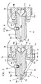
- Fig. 3 einen vergrößerten Ausschnitt aus Fig. 2,
- Fig. 4 den Ausschnitt gemäß Fig. 3 nach Austausch des Düsenkörpers mit einem gleichgestalteten Düsenkörper ohne Schiebebohrung zwecks Bildung einer offenen Düse,
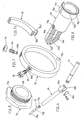
- Fig. 5 die Hohlschraube zur Verbindung der Verschlußdüse bzw. der offenen Düse mit dem Plastifizierzylinder in pespektivischer Darstellung,
- Fig. 6 zwei der Düsennadel benachbarte kraftübertragende Elemente vor Herstellung der gegenseitigen Gelenkverbindung in perspektivischer Darstellung,
- Fig. 7, 7a und 8 den Schwenkring zur Halterung kraftübertragender Elemente und den Düsenkörper je in perspektivischer Darstellung,
- Fig. 9 die Verschlußdüse mit den kraftübertragenden Elementen in Stirnansicht.
- 1 is a side view of the plasticizing unit, partly in a vertical section with the closure nozzle half open,
- 2 shows a detail of FIG. 1 in an enlarged view,
- 3 shows an enlarged detail from FIG. 2,
- 4 shows the detail according to FIG. 3 after replacement of the nozzle body with a nozzle body of the same design without a sliding hole in order to form an open nozzle,
- 5 the hollow screw for connecting the closure nozzle or the open nozzle to the plasticizing cylinder in a perspective view,
- 6 shows two perspective transmission elements adjacent to the nozzle needle before the mutual articulation is established,
- 7, 7a and 8, the swivel ring for holding force-transmitting elements and the nozzle body each in a perspective view,
- Fig. 9, the closure nozzle with the force-transmitting elements in front view.
Der Düsenkörper 70 mit Mantelfläche 70m weist einen koaxialen, sich bis zur Düsenmündung 70a˝ erstreckenden Düsenkanal 70a auf, der für den Durchfluß des Kunststoffmaterials völlig frei ist. Die den Düsenkanal 70a an der Düsenmündung 70a˝ absperrende Düsennadel 73 ist in einer spitzwinklig zum Düsenkanal 70a verlaufenden Schiebebohrung 70e aufgenommen. Der Düsenkörper 70 ist einstückig und mit einer planen Anlagefläche 70 l versehen. Der Durchmesser der Düsennadel 73 entspricht der lichten Weite der Düsenbohrung 70e, durch welche der Düsenkanal 70a hinter der Düsenmündung 70a˝ am vorderen Ende eines Mündungsabschnittes 70a′ angeschnitten ist. Bei den Steuerungsbewegungen der ein Verschlußabschnitt 73a und einen Führungsabschnitt 73b (Fig. 6) aufweisenden Düsennadel 73 gleitet deren Mantelfläche daher unmittelbar an der inneren Fläche der in den Düsenkörper eingebrachten Schiebebohrung 70e. Der Plastifizierzylinder 11 ist mit einer radialsymmetrischen Anschlußbohrung 11e zur Aufnahme eines Radialflansches 70k des Düsenkörpers 70 versehen. Die lichte Weite der Anschlußbohrung 11e entspricht dem Durchmesser eines Anschlußgewindes 72a einer Hohlschraube 72. Diese ist mit einem Radialflansch 72c mit Außenkant für den Angriff eines Werkzeuges versehen. Das Anschlußgewinde 72a der Hohlschraube 72 befindet sich im Eingriff mit einem Innengewinde in der Anschlußbohrung 11e. Dadurch ist eine ringförmige, feingeschliffene, plane Dichtfläche 70 l des Radialflansches 70k auf eine korrespondierende Dichtfläche 11a des Plastifizierzylinders 11 dichtend aufpreßbar, indem die Hohlschraube 72 über die Anlagefläche axial auf die Ringschulter 70h des Düsenkörpers 70 einwirkt. Ein axiales Verklemmen des Radialflansches 70k des Düsenkörpers 70 mit dem Plastifizierzylinder erfolgt nach lagegerechter Einjustierung dieses Düsenkörpers derart, daß die Düsennadel 73 und die kraftübertragenden Elemente symmetrisch zur vertikalen Symmetrieebene z-z (Fig. 9) liegen. Die Düsenbohrung 70a weist einen sich trichterartig verengenden Eingangsabschnitt 70a‴ auf, in welchen sich das kegelförmige Ende 70a′ des Düsenkanals 70a endet in der Düsenmündung 70a˝. Symmetrisch zur vertikalen Symmetrieebene z-z (Fig. 9) der Spritzgießeinheit ist eine Aufnahmebohrung 70g für den Thermofühler 78 des mit einer gesonderten Heizeinrichtung beheizbaren Düsenkörpers 70 eingebracht. Die Heizeinrichtung umfaßt, wie insbesondere aus Fig. 5 ersichtlich, eine Heizwendel 79 und ein auf diese aufgelegtes, mittels Schraube 84 spannbares Spannband 83, das an Spannbolzen 85 angreift.The
Mit Hilfe des Steuerzylinders 14 ist die Düsennadel 73 sowohl in Verschlußstellung als auch in Offenstellung steuerbar. Zusätzlich umschließt, wie aus Fig. 1 erkennbar, eine Spiralfeder 26 die Schaltstange 82, welche Spiralfeder 26 über einen Sprengring 87 an der Schaltstange angreift und an einem Armierungselement 51 des Plastifizierzylinders abgestützt ist. Dadurch wird die insoweit von einer Feder belastete Düsennadel 73 auch dann in Verschlußstellung gehalten, wenn die Schaltstange 82 vom Steuerzylinder 14 abgekuppelt ist.With the help of the
Der mittels radial und vertikal geführter Schieber 33′; 33˝; 33‴ in der Bohrung 10a des Trägerelementes 10 verriegelbare Plastifizierzylinder 11 ist im Gefolge einer Rückwärtsbewegung des Trägerelementes 10 für eine Auswechslung mit der Förderschnecke freisetzbar. Der Steuerzylinder 14 ist am Trägerelement 10 angeordnet und bildet bei der Freisetzungsbewegung eine Bewegungseinheit mit diesem Trägerelement 10. Die automatische Kupplung zwischen Schaltstange 82 und der Kolbenstange des Steuerzylinders 14 umfaßt, wie aus Fig. 1 erkennbar, ein an der Schaltstange 82 angeordnetes Kupplungsteil 14b und ein an der Kolbenstange des Steuerzylinders 14 angeordnetes Kupplungsteil 17. Im gekuppelten Zustand hintergreifen sich die beiden genannten Kupplungsteile, so daß sich die automatische Lösung der Kupplung durch die vertikale Bewegung des Schiebers 33; 33‴ bei der Entriegelungsbewegung ergibt. Die Kupplung ist in einer Nische T des Trägerelementes 10 angeordnet. Die Schaltstange 82 ist etwa parallel zur Spritzachse a-a in Armierungselementen 50,52 des Plastifizierzylinders 11 mittels Gleitmuffen 57 geführt. Der mit Heizeinrichtung versehene Plastifizierzylinder 11 weist eine zweiteilige Schutzabdeckung 18 auf, deren unteres Teil 18˝ die Schaltstange 82 abdeckt und deren oberes Teil 18′ einen Haltering 53 aufweist. Beide Teile sind am Armierungselement 51 des Plastifizierzylinders 11 befestigt. Der Kopf der unteren Befestigungsschraube 54 ist als Zentrierkegel ausgebildet. Dieser kann bei Abtransport der Plastifiziereinheit zur Festlegung zentrierend in entsprechenden Zentrierausnehmungen der Stellflächen der Transporteinrichtungen eingreifen. Nach einer programmgesteuerten Entriegelung des Plastifizierzylinders und nach seiner axialen Arretierung ist der Plastifizierzylinder aus dem Trägerelement 10 freisetzbar, indem dieses durch hydraulische Mittel vom Plastifizierzylinder 11 abgezogen wird. Beim Abziehen werden die an einer Steckerplatte 28′ des Trägerelementes 10 angeordneten Steckverbinder 29′ von den an einer Steckerplatte 28 des Plastifizierzylinders 11 befestigten Steckverbindern 29 getrennt.The by means of radially and vertically guided slide 33 ';33˝; 33 ‴ in the
Dem Plastifizierzylinder 11 kann ein mit dem Düsenkörper 70 hinsichtlich der äußeren Gestalt identischer Düsenkörper 170 ohne Düsenbohrung zugeordnet sein. Dieser Düsenkörper 170 ist zur bedarfsweisen Bildung einer offenen Düse 0 mit dem Düsenkörper 70 austauschbar. Wie insbesondere aus den Figuren 3 und 4 in Verbindung mit Fig. 8 erkennbar, sind die wahlweisen Düsenkörper 70; 170 mit Hilfe eines Stiftes 71 in Arbeitsposition gesichert, der zur Drehverhinderung einenends in den Düsenkörper 70 und anderenends in den Plastifizierzylinder 11 eintaucht. Wie insbesondere aus den Fign. 3 und 4 erkennbar, sind die Durchflußkanäle 70a der wahlweisen Düsenkörper 70 (für die Verschlußdüse) bzw. 170 (für die offene Düse 0) konzentrisch zur Heizwendel 79 angeordnet, so daß bei Steuerung der wahlweisen Düsen V und 0 zunächst von gleichen thermischen Bedingungen im Durchflukanal 70a ausgegangen werden kann. Wie aus Fig. 2 erkennbar, durchgreift der rückwärtige Endabschnitt 77a der Betätigungsstange 77 eine Ausnehmung 50a (Fig. 2) des benachbarten Armierungselementes 50.The
Claims (10)
dadurch gekennzeichnet, daß der Düsenkörper (70) einen koaxialen, sich bis zur Düsenmündung (70a˝) erstreckenden und für den Durchfluß des Kunststoffmaterials freien Düsenkanal (70a) aufweist und daß die den Düsenkanal (70a) an der Düsenmündung (70a˝) absperrende Düsennadel (73) in einer spitzwinklig zum Düsenkanal (70a) verlaufenden Schiebebohrung (70e) aufgenommen ist.1. Plasticizing unit on a plastic injection molding unit with associated support element (10) with a central bore (10a) for centering fastening of the plasticizing cylinder (11), which is equipped with an automatically closable nozzle (V), the approximately radially symmetrical nozzle body (70) of which a connecting thread (72a) can be connected coaxially to the plasticizing cylinder (11) and the nozzle needle (73) closing the nozzle opening (70a˝) can be controlled by a hydraulic piston-cylinder unit (control cylinder 14),
characterized in that the nozzle body (70) has a coaxial nozzle channel (70a) which extends as far as the nozzle mouth (70a˝) and is free for the flow of the plastic material, and in that the nozzle needle blocking the nozzle channel (70a) at the nozzle mouth (70a˝) (73) is received in a sliding bore (70e) that runs at an acute angle to the nozzle channel (70a).
Priority Applications (3)
| Application Number | Priority Date | Filing Date | Title |
|---|---|---|---|
| AT88102692T ATE71872T1 (en) | 1987-12-30 | 1988-02-24 | PLASTIFICATION UNIT ON A PLASTIC INJECTION MOLDING UNIT. |
| JP63118389A JPH0651321B2 (en) | 1987-12-30 | 1988-05-17 | Plasticizing nozzle assembly in synthetic resin injection molding unit |
| CA000586241A CA1290525C (en) | 1987-12-30 | 1988-12-16 | Openable and closeable nozzle for the plasticizing cylinder of an injection molding machine |
Applications Claiming Priority (2)
| Application Number | Priority Date | Filing Date | Title |
|---|---|---|---|
| DE19873744519 DE3744519A1 (en) | 1987-12-30 | 1987-12-30 | PLASTICIZING CYLINDER FOR A PLASTIC INJECTION MOLDING UNIT |
| DE3744519 | 1987-12-30 |
Publications (3)
| Publication Number | Publication Date |
|---|---|
| EP0322497A2 true EP0322497A2 (en) | 1989-07-05 |
| EP0322497A3 EP0322497A3 (en) | 1990-02-28 |
| EP0322497B1 EP0322497B1 (en) | 1992-01-22 |
Family
ID=6343843
Family Applications (1)
| Application Number | Title | Priority Date | Filing Date |
|---|---|---|---|
| EP88102692A Expired - Lifetime EP0322497B1 (en) | 1987-12-30 | 1988-02-24 | Plasticising aggregate for a plastic injection-moulding machine |
Country Status (6)
| Country | Link |
|---|---|
| US (1) | US4886439A (en) |
| EP (1) | EP0322497B1 (en) |
| DE (2) | DE3744519A1 (en) |
| ES (1) | ES2029487T3 (en) |
| HK (1) | HK100492A (en) |
| SG (1) | SG98292G (en) |
Cited By (6)
| Publication number | Priority date | Publication date | Assignee | Title |
|---|---|---|---|---|
| DE4105731C1 (en) * | 1991-02-23 | 1992-06-04 | Karl 7298 Lossburg De Hehl | |
| EP0501228A3 (en) * | 1991-02-23 | 1992-12-02 | Karl Hehl | Plasticising cylinder of a plastic injection moulding machine |
| EP0504553A3 (en) * | 1991-03-20 | 1992-12-09 | Karl Hehl | Nozzle for the plasticizing cylinder of a plastic injection moulding unit |
| DE10113352A1 (en) * | 2001-03-20 | 2002-10-02 | Karl Hehl | Lockable nozzle body and method for closing the same |
| CN111186086A (en) * | 2020-01-13 | 2020-05-22 | 杭州源航工业设计有限公司 | Rapid injection molding mechanism of injection molding machine and injection molding method thereof |
| EP4094919A1 (en) * | 2021-05-28 | 2022-11-30 | Schulze, Ebru | Multi-part machine nozzle |
Families Citing this family (9)
| Publication number | Priority date | Publication date | Assignee | Title |
|---|---|---|---|---|
| US4965361A (en) | 1989-02-27 | 1990-10-23 | Eastman Kodak Company | Preparation of 4-substituted aryl olefins |
| DE4021782A1 (en) * | 1990-07-10 | 1992-01-16 | Wolff Hans Martin | Needle valve for injection moulding machines - has needle at angle to valve axis to give clear polymer channel when open |
| DE4034784A1 (en) * | 1990-11-02 | 1992-05-07 | Karl Hehl | Plasticising unit for injection moulding machine |
| DE4105727C2 (en) * | 1990-11-02 | 1994-11-24 | Karl Hehl | Plasticizing cylinder on a plastic injection molding machine |
| DE4111164C1 (en) * | 1991-04-06 | 1992-07-02 | Karl 7298 Lossburg De Hehl | |
| US5948448A (en) * | 1997-11-18 | 1999-09-07 | Eurotool, Inc. | Apparatus for controlling plastic melt flow in injection molding machines |
| JP2004001279A (en) * | 2002-05-31 | 2004-01-08 | Toshiba Mach Co Ltd | Injection molding apparatus |
| AT517960B1 (en) * | 2016-04-12 | 2017-06-15 | Engel Austria Gmbh | Protective cover for a plasticizing cylinder |
| JP7808493B2 (en) | 2022-03-14 | 2026-01-29 | 株式会社日本製鋼所 | Injection nozzle, injection device, and injection molding machine |
Family Cites Families (13)
| Publication number | Priority date | Publication date | Assignee | Title |
|---|---|---|---|---|
| FR954395A (en) * | 1946-10-24 | 1949-12-23 | Hpm Dev Corp | Improvements to molding machines |
| US3026567A (en) * | 1958-11-10 | 1962-03-27 | Phillips Petroleum Co | Apparatus for injection molding of plastic materials |
| DE1796444U (en) * | 1959-06-04 | 1959-09-24 | Arburg Feingeraetefab Ohg | PRESS CYLINDER OF AN INJECTION MOLDING MACHINE FOR THERMOPLASTIC PLASTICS. |
| FR1439001A (en) * | 1960-02-23 | 1966-05-20 | Hydroplast Sa | Automatic pressure regulator for injection molding machines |
| IL34598A (en) * | 1969-06-07 | 1974-03-14 | Katashi Aoki | An injection molding machine |
| DE2336099A1 (en) * | 1973-07-16 | 1975-02-06 | Hehl Karl | Hydraulically regulated nozzle for an injection moulding machine - opening and closing precisely, held closed mechanically during changeover |
| US3915358A (en) * | 1974-03-01 | 1975-10-28 | Karl Hehl | Lever actuated pressure responsive injection nozzle |
| DE2835805A1 (en) * | 1978-08-16 | 1980-02-28 | Werner & Pfleiderer | Device for releasable attachment of injection orifice to cylinder - has ring nut provided with external coarse and internal fine thread to provide seal |
| AU576327B2 (en) * | 1983-09-07 | 1988-08-25 | Ray Alexander Nattrass | Injection moulding nozzle |
| US4595552A (en) * | 1984-12-13 | 1986-06-17 | Adolph Coors Company | Injection mold gate apparatus |
| DE3605219A1 (en) * | 1986-02-19 | 1987-08-20 | Karl Hehl | Injection moulding unit for a plastics injection moulding machine |
| EP0198364B1 (en) * | 1985-04-15 | 1991-01-02 | Karl Hehl | Plastics injection-moulding unit |
| DE3708434A1 (en) * | 1987-03-16 | 1989-05-24 | Karl Hehl | INJECTION MOLDING UNIT FOR A PLASTIC INJECTION MOLDING MACHINE |
-
1987
- 1987-12-30 DE DE19873744519 patent/DE3744519A1/en active Granted
-
1988
- 1988-02-24 EP EP88102692A patent/EP0322497B1/en not_active Expired - Lifetime
- 1988-02-24 DE DE8888102692T patent/DE3868039D1/en not_active Expired - Lifetime
- 1988-02-24 ES ES198888102692T patent/ES2029487T3/en not_active Expired - Lifetime
- 1988-12-27 US US07/289,821 patent/US4886439A/en not_active Expired - Fee Related
-
1992
- 1992-09-29 SG SG982/92A patent/SG98292G/en unknown
- 1992-12-10 HK HK1004/92A patent/HK100492A/en not_active IP Right Cessation
Cited By (9)
| Publication number | Priority date | Publication date | Assignee | Title |
|---|---|---|---|---|
| DE4105731C1 (en) * | 1991-02-23 | 1992-06-04 | Karl 7298 Lossburg De Hehl | |
| EP0501020A3 (en) * | 1991-02-23 | 1992-12-02 | Karl Hehl | Plasticising cylinder of a plastic injection moulding machine |
| EP0501228A3 (en) * | 1991-02-23 | 1992-12-02 | Karl Hehl | Plasticising cylinder of a plastic injection moulding machine |
| EP0504553A3 (en) * | 1991-03-20 | 1992-12-09 | Karl Hehl | Nozzle for the plasticizing cylinder of a plastic injection moulding unit |
| DE10113352A1 (en) * | 2001-03-20 | 2002-10-02 | Karl Hehl | Lockable nozzle body and method for closing the same |
| DE10113352B4 (en) * | 2001-03-20 | 2005-03-03 | Karl Hehl | Lockable nozzle body and method for closing the same |
| US7040887B2 (en) | 2001-03-20 | 2006-05-09 | Karl Hehl | Closable nozzle body |
| CN111186086A (en) * | 2020-01-13 | 2020-05-22 | 杭州源航工业设计有限公司 | Rapid injection molding mechanism of injection molding machine and injection molding method thereof |
| EP4094919A1 (en) * | 2021-05-28 | 2022-11-30 | Schulze, Ebru | Multi-part machine nozzle |
Also Published As
| Publication number | Publication date |
|---|---|
| EP0322497A3 (en) | 1990-02-28 |
| DE3744519A1 (en) | 1989-07-13 |
| DE3868039D1 (en) | 1992-03-05 |
| HK100492A (en) | 1992-12-18 |
| US4886439A (en) | 1989-12-12 |
| DE3744519C2 (en) | 1990-11-22 |
| SG98292G (en) | 1993-01-29 |
| ES2029487T3 (en) | 1992-08-16 |
| EP0322497B1 (en) | 1992-01-22 |
Similar Documents
| Publication | Publication Date | Title |
|---|---|---|
| EP0322497A2 (en) | Plasticising aggregate for a plastic injection-moulding machine | |
| DE3936289C2 (en) | Device for injection molding plastic objects containing cavities | |
| DE69228683T2 (en) | NOZZLE FOR GAS SUPPORTED INJECTION MOLDING | |
| EP0190340B1 (en) | Device for wetting mould surfaces with a liquid | |
| DE3644709C2 (en) | ||
| AT402485B (en) | INJECTION HEAD FOR INJECTION MOLDING PLASTIC BY INJECTION PROCESS | |
| DE102005017413B4 (en) | Injection nozzle with two outlet openings | |
| EP0483541A2 (en) | Plasticising apparatus for a plastic injection moulding machine | |
| EP0743162A1 (en) | Extrusion head for an extruder apparatus for the rubber or plastics industry | |
| DE102007059432A1 (en) | Piston injection unit for an injection molding machine | |
| DE3708434C2 (en) | ||
| WO2004073954A1 (en) | Needle valve nozzle | |
| EP0992332B1 (en) | Hot channel closure | |
| DE3336203A1 (en) | Injection or compression mould for processing plastics materials | |
| DE60001652T2 (en) | GAS NOZZLE AND DEVICE FOR GAS SUPPORTED INJECTION MOLDING | |
| DE3534937A1 (en) | Injection mould for plastics injection moulding machines with locking device | |
| EP0349799B1 (en) | Plastic material injection-moulding unit | |
| DE202010014740U1 (en) | Needle valve nozzle for injecting liquid plastic material | |
| DE4034577C1 (en) | ||
| DE3736634C2 (en) | ||
| EP0564908B1 (en) | Device for mixing interreacting reactive components | |
| DE19524803C1 (en) | Quick clamping device, in particular for injection molding tools | |
| DE10157549A1 (en) | Closeable injection nozzle for plasticization cylinder of injection unit for thermoplastics has a slide with transverse movement activated by axial sleeve movement against angled slide guide faces | |
| DE4430345C2 (en) | Separating device for in particular fiber-reinforced plastic mass strands | |
| DE2350016A1 (en) | INJECTION HEAD FOR PLASTICS-PROCESSING INJECTION MOLDING MACHINES WITH MULTIPLE INJECTION UNITS |
Legal Events
| Date | Code | Title | Description |
|---|---|---|---|
| PUAI | Public reference made under article 153(3) epc to a published international application that has entered the european phase |
Free format text: ORIGINAL CODE: 0009012 |
|
| AK | Designated contracting states |
Kind code of ref document: A2 Designated state(s): AT CH DE ES FR GB IT LI NL |
|
| PUAL | Search report despatched |
Free format text: ORIGINAL CODE: 0009013 |
|
| AK | Designated contracting states |
Kind code of ref document: A3 Designated state(s): AT CH DE ES FR GB IT LI NL |
|
| 17P | Request for examination filed |
Effective date: 19900724 |
|
| 17Q | First examination report despatched |
Effective date: 19910507 |
|
| GRAA | (expected) grant |
Free format text: ORIGINAL CODE: 0009210 |
|
| AK | Designated contracting states |
Kind code of ref document: B1 Designated state(s): AT CH DE ES FR GB IT LI NL |
|
| REF | Corresponds to: |
Ref document number: 71872 Country of ref document: AT Date of ref document: 19920215 Kind code of ref document: T |
|
| REF | Corresponds to: |
Ref document number: 3868039 Country of ref document: DE Date of ref document: 19920305 |
|
| ITF | It: translation for a ep patent filed | ||
| ET | Fr: translation filed | ||
| GBT | Gb: translation of ep patent filed (gb section 77(6)(a)/1977) | ||
| REG | Reference to a national code |
Ref country code: ES Ref legal event code: FG2A Ref document number: 2029487 Country of ref document: ES Kind code of ref document: T3 |
|
| PLBE | No opposition filed within time limit |
Free format text: ORIGINAL CODE: 0009261 |
|
| STAA | Information on the status of an ep patent application or granted ep patent |
Free format text: STATUS: NO OPPOSITION FILED WITHIN TIME LIMIT |
|
| 26N | No opposition filed | ||
| PGFP | Annual fee paid to national office [announced via postgrant information from national office to epo] |
Ref country code: DE Payment date: 19960119 Year of fee payment: 9 |
|
| PGFP | Annual fee paid to national office [announced via postgrant information from national office to epo] |
Ref country code: GB Payment date: 19960205 Year of fee payment: 9 |
|
| PGFP | Annual fee paid to national office [announced via postgrant information from national office to epo] |
Ref country code: FR Payment date: 19960215 Year of fee payment: 9 |
|
| PGFP | Annual fee paid to national office [announced via postgrant information from national office to epo] |
Ref country code: AT Payment date: 19960220 Year of fee payment: 9 |
|
| PGFP | Annual fee paid to national office [announced via postgrant information from national office to epo] |
Ref country code: ES Payment date: 19960227 Year of fee payment: 9 Ref country code: CH Payment date: 19960227 Year of fee payment: 9 |
|
| PGFP | Annual fee paid to national office [announced via postgrant information from national office to epo] |
Ref country code: NL Payment date: 19960228 Year of fee payment: 9 |
|
| PG25 | Lapsed in a contracting state [announced via postgrant information from national office to epo] |
Ref country code: GB Effective date: 19970224 Ref country code: AT Effective date: 19970224 |
|
| PG25 | Lapsed in a contracting state [announced via postgrant information from national office to epo] |
Ref country code: ES Free format text: LAPSE BECAUSE OF NON-PAYMENT OF DUE FEES Effective date: 19970225 |
|
| PG25 | Lapsed in a contracting state [announced via postgrant information from national office to epo] |
Ref country code: LI Effective date: 19970228 Ref country code: CH Effective date: 19970228 |
|
| PG25 | Lapsed in a contracting state [announced via postgrant information from national office to epo] |
Ref country code: NL Effective date: 19970901 |
|
| GBPC | Gb: european patent ceased through non-payment of renewal fee |
Effective date: 19970224 |
|
| REG | Reference to a national code |
Ref country code: CH Ref legal event code: PL |
|
| PG25 | Lapsed in a contracting state [announced via postgrant information from national office to epo] |
Ref country code: FR Effective date: 19971030 |
|
| PG25 | Lapsed in a contracting state [announced via postgrant information from national office to epo] |
Ref country code: DE Effective date: 19971101 |
|
| NLV4 | Nl: lapsed or anulled due to non-payment of the annual fee |
Effective date: 19970901 |
|
| REG | Reference to a national code |
Ref country code: FR Ref legal event code: ST |
|
| REG | Reference to a national code |
Ref country code: ES Ref legal event code: FD2A Effective date: 19990301 |
|
| PG25 | Lapsed in a contracting state [announced via postgrant information from national office to epo] |
Ref country code: IT Free format text: LAPSE BECAUSE OF NON-PAYMENT OF DUE FEES;WARNING: LAPSES OF ITALIAN PATENTS WITH EFFECTIVE DATE BEFORE 2007 MAY HAVE OCCURRED AT ANY TIME BEFORE 2007. THE CORRECT EFFECTIVE DATE MAY BE DIFFERENT FROM THE ONE RECORDED. Effective date: 20050224 |