EP0322460B1 - Housing structure of amplifier unit for ac spindles - Google Patents
Housing structure of amplifier unit for ac spindles Download PDFInfo
- Publication number
- EP0322460B1 EP0322460B1 EP88905431A EP88905431A EP0322460B1 EP 0322460 B1 EP0322460 B1 EP 0322460B1 EP 88905431 A EP88905431 A EP 88905431A EP 88905431 A EP88905431 A EP 88905431A EP 0322460 B1 EP0322460 B1 EP 0322460B1
- Authority
- EP
- European Patent Office
- Prior art keywords
- casing
- circuit components
- circuit
- amplifier unit
- amplifier
- Prior art date
- Legal status (The legal status is an assumption and is not a legal conclusion. Google has not performed a legal analysis and makes no representation as to the accuracy of the status listed.)
- Expired - Lifetime
Links
Images

Classifications
-
- H—ELECTRICITY
- H05—ELECTRIC TECHNIQUES NOT OTHERWISE PROVIDED FOR
- H05K—PRINTED CIRCUITS; CASINGS OR CONSTRUCTIONAL DETAILS OF ELECTRIC APPARATUS; MANUFACTURE OF ASSEMBLAGES OF ELECTRICAL COMPONENTS
- H05K7/00—Constructional details common to different types of electric apparatus
- H05K7/14—Mounting supporting structure in casing or on frame or rack
- H05K7/1422—Printed circuit boards receptacles, e.g. stacked structures, electronic circuit modules or box like frames
- H05K7/1427—Housings
- H05K7/1432—Housings specially adapted for power drive units or power converters
- H05K7/14324—Housings specially adapted for power drive units or power converters comprising modular units, e.g. DIN rail mounted units
-
- H—ELECTRICITY
- H05—ELECTRIC TECHNIQUES NOT OTHERWISE PROVIDED FOR
- H05K—PRINTED CIRCUITS; CASINGS OR CONSTRUCTIONAL DETAILS OF ELECTRIC APPARATUS; MANUFACTURE OF ASSEMBLAGES OF ELECTRICAL COMPONENTS
- H05K7/00—Constructional details common to different types of electric apparatus
- H05K7/14—Mounting supporting structure in casing or on frame or rack
- H05K7/1422—Printed circuit boards receptacles, e.g. stacked structures, electronic circuit modules or box like frames
- H05K7/1427—Housings
- H05K7/1432—Housings specially adapted for power drive units or power converters
-
- H—ELECTRICITY
- H05—ELECTRIC TECHNIQUES NOT OTHERWISE PROVIDED FOR
- H05K—PRINTED CIRCUITS; CASINGS OR CONSTRUCTIONAL DETAILS OF ELECTRIC APPARATUS; MANUFACTURE OF ASSEMBLAGES OF ELECTRICAL COMPONENTS
- H05K7/00—Constructional details common to different types of electric apparatus
- H05K7/14—Mounting supporting structure in casing or on frame or rack
- H05K7/1462—Mounting supporting structure in casing or on frame or rack for programmable logic controllers [PLC] for automation or industrial process control
- H05K7/1468—Mechanical features of input/output (I/O) modules
- H05K7/1471—Modules for controlling actuators
Definitions
- the present invention relates to an amplifier unit for an AC spindle having a casing structure for containing an amplifier unit which comprises various circuit components, for amplifying power supplied from a power source and supply amplified driving power to an AC motor for rotatively driving the spindle of a machine tool, and structurally capable of forming an individual amplifier assembly, and more particularly, to an improved casing structure for such an amplifier unit for an AC spindle, capable of enabling an efficient automatic assembly of the amplifier unit before the unit is accommodated in a power panel forming the electrical assembly of a machine tool, and capable of being formed in a lightweight construction.
- a desired power is supplied to an AC motor for rotatively driving the spindle of a machine tool at a high speed, from a power source through an AC amplifier provided on and contained in a power panel provided as one of the components of the electrical assembly or an electrical unit.
- an AC amplifier comprises various circuit components, such as an electric contactor circuit for switching, a reactor circuit for shutting off external noise signals and for preventing the emission of noise signals, a rectifying circuit, a power amplifier circuit, and an inverter circuit.
- these circuit components are those available on the market and are arranged within the casing so as to meet the output level of the AC motor, and then the assembly of the circuit components and the casing is attached to the power panel.
- the casing employs a box formed by cutting and bending an inexpensive steel plate or the like, the circuit components are arranged within the box so that the circuit components are concealed in the casing, and then the circuit components are screwed firmly to the bottom wall of the box (see e.g. JP-A-60-151202).
- the bit of a screw driver namely, a tool for assembling the amplifier unit
- the bit of a screw driver must be necessarily inserted deep into the box near to the bottom wall of the box along the circuit components, the tip of the screw driver inserted in the head of a screw, and the screw driver then turned to fasten the circuit unit with the screw.
- an assembling process including inserting a screw driver gripped at the extremity of a robot hand in the box and rotating the screw driver to fasten the screw requires a step of lowering the robot hand to a position at which the tip of the screw driver is inserted in the head of the screw, and a step of raising the robot hand after fastening the screw, and this is one of the factors that adversely affects the efficiency of the automatic assembling process and remarkably reduces the working efficiency.
- a novel casing structure having an improved design for an amplifier unit for an AC spindle capable of enabling a highly efficient automatic assembly of the amplifier unit by using an industrial robot.
- an object of the present invention is to provide a novel casing structure for an amplifier for an AC spindle, meeting this demand.
- Another object of the present invention is to provide a casing structure to facilitate an automatic assembly of an amplifier unit for an AC spindle by the end effector of a manipulator for such an automatic assembly, such as an industrial robot.
- the present invention provides an amplifier unit for an AC spindle, electrically interposed between an AC motor for driving the spindle of a machine tool and a power source and comprising a plurality of circuit components forming an electric amplifier integrally contained in a single casing having a ceiling means opening upward, a fixing seat means formed on the ceiling means respectively at predetermined positions in a predetermined arrangement so as to fixedly receive the attachments of the plurality of circuit components of the electric amplifier thereon, respectively, and positioning plate means disposed respectively around the predetermined positions to guide the circuit components so that the attachments of the circuit components are aligned with and seated on the corresponding fixing seat means, respectively, and the plurality of circuit components are fastened to the ceiling means from above the casing.
- the process for inserting the screw driver for fastening the screws in the interior of the casing by the robot is omitted because the plurality of circuit components are fastened to the ceiling means of the casing, and thus the efficiency of the assembly work is enhanced and the positioning plate means enables an accurate positioning of the circuit components respectively at the predetermined positions by the automatic operation of the robot.
- the casing is a molded structure formed of a synthetic resin to form the amplifier unit for the AC spindle in a lightweight construction.
- the amplifier comprises electric circuits including an input terminal unit A, an electromagnetic contactor B, a reactor circuit C for shutting off noise from external circuits and for preventing the emission of noise generated by the switching operation of the amplifier, a rectifying bridge circuit D comprising a plurality of transistors, a power diode circuit E, the resistance F of the energy regenerating circuit of an AC motor M, a capacitor G for storing the regenerated energy, an inverter circuit H comprising a plurality of transistors, and an output terminal unit J.
- the amplifier supplies a desired power to the AC motor M for driving the spindle.
- These electric circuits are individual, integral electric components, respectively.
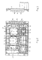
- the construction of a casing for accommodating the circuit components A to J will be described hereinafter with reference to Figs. 1 to 3.
- the casing 10 embodying the present invention is a lightweight, molded box of a synthetic resin, comprising a plate-shaped section 12 for holding the comparatively flat circuit components, and a concave section 14 for holding the comparatively thick circuit components.
- Terminal mounts 16a and 16b respectively for holding the input terminal unit A and the output terminal unit J are provided on one side of the casing 10.
- Indicated at 16c is a grounding terminal mount.
- the plate-shaped section 12 has, in a sequential arrangement from left to right as viewed in the drawings, mounting areas 12a to 12c to be mounted respectively with the power diode circuit E, the rectifying bridge circuit D, and the inverter circuit H.
- the concave section 14 has, in a sequential arrangement from left to right as viewed in the drawings, mounting areas 14a to 14c to be mounted respectively with the capacitor G, the reactor circuit C, and the electromagnetic contactor B.
- Component fixing seats are formed in the mounting areas 12a to 12c in the upper ceiling surface of the casing 10, and the components E, D, and H are positioned on the component fixing seats.
- fastening screws or bolts are passed through through-holes 20 formed in the attachments 18 of the circuit component in the direction of an arrow S, by the hand of an industrial robot, and then the fastening screws are turned with a screw driver, not shown, gripped by the hand to fasten the attachments to the fixing seat to complete the mounting of the circuit component.
- Threaded holes are formed beforehand in the fixing seats at positions respectively corresponding to the through-holes 20 of the attachments 18 of the circuit components E, D, and H, or a separate fixing plate is disposed behind the plates-shaped section 12 and threaded holes are formed at positions respectively corresponding to the through-holes 20 of the attachments 18.
- threaded holes are formed in a different casing of a different electric unit of the electric assembly of a machine tool at positions respectively corresponding to the through-holes 20 of the attachments 18 to enable the simple attachment of the electric components to the different casing by a fixing operation from above the casing 10.
- a plurality of lengthwise plate-shaped ribs 22 each having an inclined surface 24 declining toward the corresponding fixing seat are formed around the mounting areas 12a, 12b, and 12c forming the fixing seat for the electric components, to mechanically reinforce the ceiling surface of the casing 10.
- These inclined surfaces 24 have the function of a template for guiding the circuit components E, D, and H and automatically positioning the circuit components E, D, and H at the respective centers of the fixing seats when lowering the circuit components E, D and H from above the casing 10, and positioning the same in the corresponding fixing seats by the robot. Accordingly, when assembling the amplifier unit for the AC spindle by means of the industrial robot, the circuit components E, D, and H can be accurately positioned in the corresponding fixing seats.
- the concave section 14 has supporting posts 26 extending upward from the bottom surface 10a of the casing 10 in the mounting areas 14a to 14c.
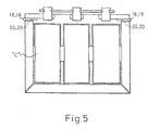
- the supporting posts 26 for receiving the attachments 18 of the reactor circuit C thereon are shown in Fig. 5 by way of example. Threaded holes 28 are formed respectively in the upper ends of the supporting posts 26.
- the fastening screws are passed through the through-holes 20 formed in the attachments 18 of the circuit component, for example, the reactor circuit C, from above the casing 10 in the direction of the arrow S and, as mentioned above, the fastening screws are fastened by the robot to fasten the circuit component to the ceiling section 14 through a fastening operation above the casing 10.
- thin, lengthwise, plate-shaped ribs 22 are formed, similar to those formed in the plate-shaped section 12, around the mounting areas 14a to 14c of the concave section 14 so that the circuit components F, C, and B are positioned automatically at predetermined positions respectively by the guiding function of the inclined surfaces 24 declining inward when the circuit components F, C, and B gripped by the robot are lowered. Therefore, the circuit components F, C, and B are positioned so that the attachments 18 thereof are placed accurately on the corresponding supporting posts 26 to facilitate the subsequent screwing operation for fastening the circuit components F, C, and B to the supporting posts 26.
- fixing seats for joining the casing 10 to other electric equipment on the power panel of the electric unit of the machine tool is provided in the periphery of the casing 10.
- the casing 10 may be provided with additional fixing seats in preparation for fixing circuit components other than foregoing circuit components thereto, when necessary.
- the casing 10 may be provided on the walls thereof with radiating fins, to improve the heat-radiating effect of the circuit components or a cover member provided with radiating fins may be provided on the ceiling surface to promote the effect of heat radiation from the interior of the casing 10.
- the structure of the casing in accordance with the present invention for an amplifier unit for an AC spindle enables assembly work, such as a positioning operation and a screwing operation, to be carried out above the casing, namely, in the ceiling section, when attaching the electrical circuit components A to J of the amplifier unit to the casing.
- the stroke of the end effector held on the extremity of the robot can be reduced to the minimum necessary extent; that is, compared with the conventional assembly work in which the screw driver for fastening the screws is inserted deep into the interior of the casing to fasten the screw and then the screw driver is raised after fastening the screw, the stroke of the screw driver in the assembling work to attach the amplifier components to the casing of the present invention is remarkably reduced. Furthermore, the thin, lengthwise, plate-shaped ribs improve the accuracy of positioning the electric components of the amplifier unit. Moreover, since this casing is formed in a lightweight construction by molding a synthetic resin, the overall weight of the amplifier unit for the AC spindle is reduced.
- the foregoing casing is designed in an appropriate shape and size determined in connection with the number and shape of the circuit components to be mounted on the casing and, of course, the shape and size of the casing are not limited to those shown in the drawings. That is, it is obvious that the casing may be formed in an optional shape and size without departing from the technical idea of attaching the circuit component to the ceiling surface and guiding them by positioning means, in the preferred embodiment by forming inclined surfaces having the function of a template respectively in the ribs.
Abstract
Description
- The present invention relates to an amplifier unit for an AC spindle having a casing structure for containing an amplifier unit which comprises various circuit components, for amplifying power supplied from a power source and supply amplified driving power to an AC motor for rotatively driving the spindle of a machine tool, and structurally capable of forming an individual amplifier assembly, and more particularly, to an improved casing structure for such an amplifier unit for an AC spindle, capable of enabling an efficient automatic assembly of the amplifier unit before the unit is accommodated in a power panel forming the electrical assembly of a machine tool, and capable of being formed in a lightweight construction.
- A desired power is supplied to an AC motor for rotatively driving the spindle of a machine tool at a high speed, from a power source through an AC amplifier provided on and contained in a power panel provided as one of the components of the electrical assembly or an electrical unit. Usually, to receive power from a three-phase power source and to supply a desired current necessary for rotatively driving the AC motor, such an AC amplifier comprises various circuit components, such as an electric contactor circuit for switching, a reactor circuit for shutting off external noise signals and for preventing the emission of noise signals, a rectifying circuit, a power amplifier circuit, and an inverter circuit. Conventionally, these circuit components are those available on the market and are arranged within the casing so as to meet the output level of the AC motor, and then the assembly of the circuit components and the casing is attached to the power panel. The casing employs a box formed by cutting and bending an inexpensive steel plate or the like, the circuit components are arranged within the box so that the circuit components are concealed in the casing, and then the circuit components are screwed firmly to the bottom wall of the box (see e.g. JP-A-60-151202).
- In process for assembling the amplifier unit for the AC spindle by screwing the circuit components of the amplifier unit to the bottom wall of the box formed of a metallic plate, the bit of a screw driver, namely, a tool for assembling the amplifier unit, must be necessarily inserted deep into the box near to the bottom wall of the box along the circuit components, the tip of the screw driver inserted in the head of a screw, and the screw driver then turned to fasten the circuit unit with the screw. Accordingly, in assembling the amplifier unit by an automatic assembling process, for example, an assembling process employing an industrial robot, an assembling process including inserting a screw driver gripped at the extremity of a robot hand in the box and rotating the screw driver to fasten the screw requires a step of lowering the robot hand to a position at which the tip of the screw driver is inserted in the head of the screw, and a step of raising the robot hand after fastening the screw, and this is one of the factors that adversely affects the efficiency of the automatic assembling process and remarkably reduces the working efficiency. Accordingly, there is a demand for a novel casing structure having an improved design for an amplifier unit for an AC spindle, capable of enabling a highly efficient automatic assembly of the amplifier unit by using an industrial robot.
- Accordingly, an object of the present invention is to provide a novel casing structure for an amplifier for an AC spindle, meeting this demand.
- Another object of the present invention is to provide a casing structure to facilitate an automatic assembly of an amplifier unit for an AC spindle by the end effector of a manipulator for such an automatic assembly, such as an industrial robot.
- The present invention provides an amplifier unit for an AC spindle, electrically interposed between an AC motor for driving the spindle of a machine tool and a power source and comprising a plurality of circuit components forming an electric amplifier integrally contained in a single casing having a ceiling means opening upward, a fixing seat means formed on the ceiling means respectively at predetermined positions in a predetermined arrangement so as to fixedly receive the attachments of the plurality of circuit components of the electric amplifier thereon, respectively, and positioning plate means disposed respectively around the predetermined positions to guide the circuit components so that the attachments of the circuit components are aligned with and seated on the corresponding fixing seat means, respectively, and the plurality of circuit components are fastened to the ceiling means from above the casing. In assembling this amplifier unit for the AC spindle, the process for inserting the screw driver for fastening the screws in the interior of the casing by the robot is omitted because the plurality of circuit components are fastened to the ceiling means of the casing, and thus the efficiency of the assembly work is enhanced and the positioning plate means enables an accurate positioning of the circuit components respectively at the predetermined positions by the automatic operation of the robot. Preferably, the casing is a molded structure formed of a synthetic resin to form the amplifier unit for the AC spindle in a lightweight construction.
- The above and other objects, features and advantages of the present invention will become more apparent from the following description taken in conjunction with the accompanying drawings, in which;
- Figure 1 is a perspective view of a casing embodying the present invention, for an amplifier unit for an AC spindle;
- Figure 2 is a top plan view of the casing of Fig. 1;
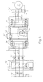
- Figure 3 is a side elevation showing one side face of the casing of Fig. 1;
- Figure 4 is a circuit diagram exemplifying one of various amplifiers for an AC spindle; and
- Figure 5 is a side elevation of one of the circuit components shown in Fig. 2.
- First, referring to Fig. 4 showing a circuit diagram of an amplifier for an AC spindle, the amplifier comprises electric circuits including an input terminal unit A, an electromagnetic contactor B, a reactor circuit C for shutting off noise from external circuits and for preventing the emission of noise generated by the switching operation of the amplifier, a rectifying bridge circuit D comprising a plurality of transistors, a power diode circuit E, the resistance F of the energy regenerating circuit of an AC motor M, a capacitor G for storing the regenerated energy, an inverter circuit H comprising a plurality of transistors, and an output terminal unit J. The amplifier supplies a desired power to the AC motor M for driving the spindle. These electric circuits are individual, integral electric components, respectively.
- The construction of a casing for accommodating the circuit components A to J will be described hereinafter with reference to Figs. 1 to 3. The
casing 10 embodying the present invention is a lightweight, molded box of a synthetic resin, comprising a plate-shaped section 12 for holding the comparatively flat circuit components, and aconcave section 14 for holding the comparatively thick circuit components.Terminal mounts casing 10. Indicated at 16c is a grounding terminal mount. - Referring to Figs. 2 and 3 in combination with Fig. 1, the plate-
shaped section 12 has, in a sequential arrangement from left to right as viewed in the drawings, mountingareas 12a to 12c to be mounted respectively with the power diode circuit E, the rectifying bridge circuit D, and the inverter circuit H. Theconcave section 14 has, in a sequential arrangement from left to right as viewed in the drawings, mountingareas 14a to 14c to be mounted respectively with the capacitor G, the reactor circuit C, and the electromagnetic contactor B. Component fixing seats are formed in themounting areas 12a to 12c in the upper ceiling surface of thecasing 10, and the components E, D, and H are positioned on the component fixing seats. As is obvious from Figures 2 and 5, fastening screws or bolts, not shown are passed through through-holes 20 formed in the attachments 18 of the circuit component in the direction of an arrow S, by the hand of an industrial robot, and then the fastening screws are turned with a screw driver, not shown, gripped by the hand to fasten the attachments to the fixing seat to complete the mounting of the circuit component. Threaded holes are formed beforehand in the fixing seats at positions respectively corresponding to the through-holes 20 of the attachments 18 of the circuit components E, D, and H, or a separate fixing plate is disposed behind the plates-shaped section 12 and threaded holes are formed at positions respectively corresponding to the through-holes 20 of the attachments 18. Further, threaded holes are formed in a different casing of a different electric unit of the electric assembly of a machine tool at positions respectively corresponding to the through-holes 20 of the attachments 18 to enable the simple attachment of the electric components to the different casing by a fixing operation from above thecasing 10. - It should be particularly noted that a plurality of lengthwise plate-
shaped ribs 22 each having aninclined surface 24 declining toward the corresponding fixing seat are formed around themounting areas casing 10. Theseinclined surfaces 24 have the function of a template for guiding the circuit components E, D, and H and automatically positioning the circuit components E, D, and H at the respective centers of the fixing seats when lowering the circuit components E, D and H from above thecasing 10, and positioning the same in the corresponding fixing seats by the robot. Accordingly, when assembling the amplifier unit for the AC spindle by means of the industrial robot, the circuit components E, D, and H can be accurately positioned in the corresponding fixing seats. - On the other hand, the
concave section 14 has supportingposts 26 extending upward from thebottom surface 10a of thecasing 10 in themounting areas 14a to 14c. The supportingposts 26 for receiving the attachments 18 of the reactor circuit C thereon are shown in Fig. 5 by way of example. Threadedholes 28 are formed respectively in the upper ends of the supportingposts 26. The fastening screws, not shown, are passed through the through-holes 20 formed in the attachments 18 of the circuit component, for example, the reactor circuit C, from above thecasing 10 in the direction of the arrow S and, as mentioned above, the fastening screws are fastened by the robot to fasten the circuit component to theceiling section 14 through a fastening operation above thecasing 10. Furthermore, thin, lengthwise, plate-shaped ribs 22 are formed, similar to those formed in the plate-shaped section 12, around themounting areas 14a to 14c of theconcave section 14 so that the circuit components F, C, and B are positioned automatically at predetermined positions respectively by the guiding function of theinclined surfaces 24 declining inward when the circuit components F, C, and B gripped by the robot are lowered. Therefore, the circuit components F, C, and B are positioned so that the attachments 18 thereof are placed accurately on the corresponding supportingposts 26 to facilitate the subsequent screwing operation for fastening the circuit components F, C, and B to the supportingposts 26. - Furthermore, fixing seats for joining the
casing 10 to other electric equipment on the power panel of the electric unit of the machine tool is provided in the periphery of thecasing 10. Naturally, thecasing 10 may be provided with additional fixing seats in preparation for fixing circuit components other than foregoing circuit components thereto, when necessary. Although not shown, thecasing 10 may be provided on the walls thereof with radiating fins, to improve the heat-radiating effect of the circuit components or a cover member provided with radiating fins may be provided on the ceiling surface to promote the effect of heat radiation from the interior of thecasing 10. - As is apparent from the foregoing description, the structure of the casing in accordance with the present invention for an amplifier unit for an AC spindle enables assembly work, such as a positioning operation and a screwing operation, to be carried out above the casing, namely, in the ceiling section, when attaching the electrical circuit components A to J of the amplifier unit to the casing. Accordingly, when carrying out the automatic assembly of the amplifier unit for the AC spindle along a production line by using a manipulator, such as an industrial robot, the stroke of the end effector held on the extremity of the robot can be reduced to the minimum necessary extent; that is, compared with the conventional assembly work in which the screw driver for fastening the screws is inserted deep into the interior of the casing to fasten the screw and then the screw driver is raised after fastening the screw, the stroke of the screw driver in the assembling work to attach the amplifier components to the casing of the present invention is remarkably reduced. Furthermore, the thin, lengthwise, plate-shaped ribs improve the accuracy of positioning the electric components of the amplifier unit. Moreover, since this casing is formed in a lightweight construction by molding a synthetic resin, the overall weight of the amplifier unit for the AC spindle is reduced.
- The foregoing casing is designed in an appropriate shape and size determined in connection with the number and shape of the circuit components to be mounted on the casing and, of course, the shape and size of the casing are not limited to those shown in the drawings. That is, it is obvious that the casing may be formed in an optional shape and size without departing from the technical idea of attaching the circuit component to the ceiling surface and guiding them by positioning means, in the preferred embodiment by forming inclined surfaces having the function of a template respectively in the ribs.
-
- 10
- Casing
- 10a
- Bottom surface
- 12
- Plate-shaped section
- 12a to 12c
- Mounting areas
- 14
- Concave section
- 14a to 14c
- Mounting areas
- 16a, 16b, 16c
- Terminal mounts
- 18
- Attachments
- 20
- Through holes
- 22
- Thin, lengthwise, plate-shaped rib
- 24
- Inclined surface
- 26
- Supporting post
- 28
- Threaded hole
- A
- Input terminal unit
- B
- Electromagnetic contactor
- C
- Reactor circuit
- D
- Rectifying bridge circuit
- E
- Power diode circuit
- F
- Resistance
- G
- Capacitor
- H
- Inverter circuit
- J
- Output terminal unit
- M
- AC motor for driving the spindle
Claims (6)
- An amplifier unit for an AC spindle, interposed between an AC motor (M) for driving the spindle of a machine and a power source, and comprising a plurality of circuit components (A-J) constituting an electric amplifier, and a casing (10) integrally containing the circuit components (A-J) characterized in that the casing (10) has a ceiling means opening upward, a fixing seat means (24,26) formed on the ceiling means respectively at predetermined positions in a predetermined arrangement to fixedly receive attachments (18) of the plurality of integral circuit components (A-J) of the amplifier thereon, respectively, and positioning plate means (22,24) formed respectively around the predetermined positions to guide the circuit comnonents (A-J) so that the attachments (18) of the circuit components (A-J) are aligned with and seated on the corresponding fixing seat means (24,26) respectively, and the plurality of circuit components (A-J) are fastened to the ceiling means from above the casing (10).
- An amplifier unit for an AC spindle according to Claim 1, wherein through holes (20) are formed respectively in the attachments (18) of said plurality of circuit components (A-J), and threaded holes (28) are formed in the fixing seat means (26) of said casing (10) corresponding to the through-holes (20) of the attachments (18) to be seated thereon.
- An amplifier unit for an AC spindle according to Claim 2, wherein said fixing seat means (24,26) comprises lengthwise supporting posts (26), and said threaded holes (28) are formed in free ends of the supporting posts (26).
- An amplifier unit for an AC spindle according to Claim 1, wherein the positioning plate means (22,24) of said casing (10) is a lengthwise, thin plate-shaped rib (22) having an inclined surface (24) declining toward said predetermined position.
- An amplifier unit for an AC spindle according to Claim 1, wherein said casing (10) having said fixing seat means (24,26) and said positioning plate means (22,24) is formed by molding a synthetic resin.
- An amplifier unit for an AC spindle according to Claim 1, wherein said plurality of circuit components (A-J) are an electromagnetic contactor circuit assembly (B) having input terminals (A) to be connected to a power source, a reactor circuit assembly (C), a rectifier circuit assembly (D), a power diode circuit assembly (E) and an inverter circuit assembly (H), said plurality of circuit components are electrically connected sequentially, said electric amplifier is connected to input terminals (J) of said AC motor (M), and said plurality of circuit components are contained in said casing (10) in a predetermined arrangement.
Applications Claiming Priority (2)
| Application Number | Priority Date | Filing Date | Title |
|---|---|---|---|
| JP148012/87 | 1987-06-16 | ||
| JP62148012A JPH0834714B2 (en) | 1987-06-16 | 1987-06-16 | AC spindle amplifier housing structure |
Publications (3)
| Publication Number | Publication Date |
|---|---|
| EP0322460A1 EP0322460A1 (en) | 1989-07-05 |
| EP0322460A4 EP0322460A4 (en) | 1990-01-24 |
| EP0322460B1 true EP0322460B1 (en) | 1993-02-10 |
Family
ID=15443131
Family Applications (1)
| Application Number | Title | Priority Date | Filing Date |
|---|---|---|---|
| EP88905431A Expired - Lifetime EP0322460B1 (en) | 1987-06-16 | 1988-06-16 | Housing structure of amplifier unit for ac spindles |
Country Status (5)
| Country | Link |
|---|---|
| US (1) | US5012173A (en) |
| EP (1) | EP0322460B1 (en) |
| JP (1) | JPH0834714B2 (en) |
| DE (1) | DE3878432T2 (en) |
| WO (1) | WO1988010533A1 (en) |
Families Citing this family (12)
| Publication number | Priority date | Publication date | Assignee | Title |
|---|---|---|---|---|
| JPH0834714B2 (en) * | 1987-06-16 | 1996-03-29 | ファナック株式会社 | AC spindle amplifier housing structure |
| JP2809026B2 (en) * | 1992-09-30 | 1998-10-08 | 三菱電機株式会社 | INVERTER DEVICE AND METHOD OF USING INVERTER DEVICE |
| JP3100834B2 (en) * | 1994-06-30 | 2000-10-23 | 三菱電機株式会社 | Electric power steering circuit device |
| JP3644835B2 (en) * | 1999-01-18 | 2005-05-11 | 三菱電機株式会社 | Electric power steering circuit device |
| DE20106518U1 (en) * | 2001-04-14 | 2001-06-07 | Dewert Antriebs Systemtech | Electric motor drive |
| EP1363026A3 (en) * | 2002-04-26 | 2004-09-01 | Denso Corporation | Invertor integrated motor for an automotive vehicle |
| JP5175452B2 (en) * | 2005-12-28 | 2013-04-03 | 東芝シュネデール・インバータ株式会社 | Inverter device |
| ES2504515T3 (en) * | 2007-05-25 | 2014-10-08 | Sma Solar Technology Ag | Investor Housing |
| EP2710868B1 (en) * | 2011-05-17 | 2017-08-23 | Carrier Corporation | Variable frequency drive heat sink assembly |
| JP2014141106A (en) * | 2011-09-21 | 2014-08-07 | Autoliv Development Ab | Control device for occupant restraint apparatus |
| CN103875316B (en) | 2011-10-07 | 2016-10-26 | 沙特基础全球技术有限公司 | Inverter case system |
| WO2014080462A1 (en) * | 2012-11-21 | 2014-05-30 | 三洋電機株式会社 | Power conversion apparatus |
Family Cites Families (13)
| Publication number | Priority date | Publication date | Assignee | Title |
|---|---|---|---|---|
| JPS51133721A (en) * | 1975-05-14 | 1976-11-19 | Yutaka Nakamoto | System for sequential motor group control |
| JPS54115777A (en) * | 1978-02-28 | 1979-09-08 | Nippon Electric Co | Electromagnetic relay |
| US4218724A (en) * | 1978-11-21 | 1980-08-19 | Kaufman Lance R | Compact circuit package having improved circuit connectors |
| DE3031287A1 (en) * | 1980-08-19 | 1982-04-08 | A.S.R. Servotron GmbH für industrielle Automations Systeme, 8012 Ottobrunn | TRANSISTOR CONTROL UNIT FOR A SERVOMOTOR |
| US4520425A (en) * | 1982-08-12 | 1985-05-28 | Mitsubishi Denki Kabushiki Kaisha | Control apparatus with improved structure for cooling circuit elements |
| JPS60151202A (en) * | 1983-08-25 | 1985-08-09 | Yuka Meramin Kk | Manufacture of boron nitride |
| JPS60151202U (en) * | 1984-03-16 | 1985-10-08 | フアナツク株式会社 | control panel |
| JPS614172A (en) * | 1984-06-18 | 1986-01-10 | ファナック株式会社 | Ac motor control board |
| US4621200A (en) * | 1985-02-11 | 1986-11-04 | Lovrenich Rodger T | Control device including a conductively isolated depluggable controller |
| US4769557A (en) * | 1987-02-19 | 1988-09-06 | Allen-Bradley Company, Inc. | Modular electric load controller |
| JP2651911B2 (en) * | 1987-04-24 | 1997-09-10 | 蛇の目ミシン工業株式会社 | Computer board mounting equipment for computer sewing machines. |
| JPH0834714B2 (en) * | 1987-06-16 | 1996-03-29 | ファナック株式会社 | AC spindle amplifier housing structure |
| US4870863A (en) * | 1987-09-17 | 1989-10-03 | Square D Company | Modular switch device |
-
1987
- 1987-06-16 JP JP62148012A patent/JPH0834714B2/en not_active Expired - Lifetime
-
1988
- 1988-06-16 DE DE8888905431T patent/DE3878432T2/en not_active Expired - Fee Related
- 1988-06-16 EP EP88905431A patent/EP0322460B1/en not_active Expired - Lifetime
- 1988-06-16 WO PCT/JP1988/000589 patent/WO1988010533A1/en active IP Right Grant
- 1988-06-16 US US07/334,275 patent/US5012173A/en not_active Expired - Fee Related
Also Published As
| Publication number | Publication date |
|---|---|
| EP0322460A4 (en) | 1990-01-24 |
| US5012173A (en) | 1991-04-30 |
| DE3878432D1 (en) | 1993-03-25 |
| WO1988010533A1 (en) | 1988-12-29 |
| DE3878432T2 (en) | 1993-07-29 |
| JPS63314197A (en) | 1988-12-22 |
| JPH0834714B2 (en) | 1996-03-29 |
| EP0322460A1 (en) | 1989-07-05 |
Similar Documents
| Publication | Publication Date | Title |
|---|---|---|
| US4908738A (en) | Drive motor control unit | |
| EP0322460B1 (en) | Housing structure of amplifier unit for ac spindles | |
| US5497289A (en) | Inverter apparatus and method therefor | |
| JP2002337073A (en) | Power tool | |
| EP0290617B1 (en) | Control unit | |
| EP0190835A1 (en) | Fan Mounting | |
| US5194772A (en) | A-c driven motor and method for forming input terminals thereof | |
| WO2019163406A1 (en) | Electric compressor | |
| US20210066985A1 (en) | Motor drive apparatus having electric power flowing into/out of power device through bus bar | |
| JPH0886473A (en) | Outdoor machine of air conditioner | |
| JPH0594854A (en) | Power module and power module board | |
| JPH08289566A (en) | Motor driver | |
| JP2019143604A (en) | Motor compressor | |
| JPS63157634A (en) | Motor drive unit | |
| CN214771862U (en) | Electric pick shell convenient to maintenance | |
| JP2006333591A (en) | Inverter device | |
| CN215419067U (en) | Electrical cabinet | |
| CN212822794U (en) | Drilling tool for machining | |
| CN219726124U (en) | Electric tool and main body structure thereof | |
| CN220107702U (en) | Motor shell and motor | |
| CN218939869U (en) | Energy storage device and energy storage device box thereof | |
| JP3023043B2 (en) | Tabletop robot | |
| TW202234984A (en) | Inverter device, motor module and vehicle an inverter device, comprising: a power module, a driving circuit board and mask plate | |
| JPH09159219A (en) | Outdoor unit for air conditioner | |
| JPS63157635A (en) | Motor drive unit |
Legal Events
| Date | Code | Title | Description |
|---|---|---|---|
| PUAI | Public reference made under article 153(3) epc to a published international application that has entered the european phase |
Free format text: ORIGINAL CODE: 0009012 |
|
| 17P | Request for examination filed |
Effective date: 19890309 |
|
| AK | Designated contracting states |
Kind code of ref document: A1 Designated state(s): DE FR GB |
|
| A4 | Supplementary search report drawn up and despatched |
Effective date: 19900124 |
|
| 17Q | First examination report despatched |
Effective date: 19920401 |
|
| GRAA | (expected) grant |
Free format text: ORIGINAL CODE: 0009210 |
|
| AK | Designated contracting states |
Kind code of ref document: B1 Designated state(s): DE FR GB |
|
| PG25 | Lapsed in a contracting state [announced via postgrant information from national office to epo] |
Ref country code: FR Effective date: 19930210 |
|
| REF | Corresponds to: |
Ref document number: 3878432 Country of ref document: DE Date of ref document: 19930325 |
|
| PG25 | Lapsed in a contracting state [announced via postgrant information from national office to epo] |
Ref country code: GB Effective date: 19930616 |
|
| EN | Fr: translation not filed | ||
| PLBE | No opposition filed within time limit |
Free format text: ORIGINAL CODE: 0009261 |
|
| STAA | Information on the status of an ep patent application or granted ep patent |
Free format text: STATUS: NO OPPOSITION FILED WITHIN TIME LIMIT |
|
| 26N | No opposition filed | ||
| GBPC | Gb: european patent ceased through non-payment of renewal fee |
Effective date: 19930616 |
|
| PGFP | Annual fee paid to national office [announced via postgrant information from national office to epo] |
Ref country code: DE Payment date: 19960612 Year of fee payment: 9 |
|
| PG25 | Lapsed in a contracting state [announced via postgrant information from national office to epo] |
Ref country code: DE Free format text: LAPSE BECAUSE OF NON-PAYMENT OF DUE FEES Effective date: 19980303 |