EP0321684A2 - Pressure container, such as a pressure reactor or pressure waste heat boiler - Google Patents
Pressure container, such as a pressure reactor or pressure waste heat boiler Download PDFInfo
- Publication number
- EP0321684A2 EP0321684A2 EP88118293A EP88118293A EP0321684A2 EP 0321684 A2 EP0321684 A2 EP 0321684A2 EP 88118293 A EP88118293 A EP 88118293A EP 88118293 A EP88118293 A EP 88118293A EP 0321684 A2 EP0321684 A2 EP 0321684A2
- Authority
- EP
- European Patent Office
- Prior art keywords
- pressure
- cooling water
- wall construction
- tube wall
- cooling
- Prior art date
- Legal status (The legal status is an assumption and is not a legal conclusion. Google has not performed a legal analysis and makes no representation as to the accuracy of the status listed.)
- Granted
Links
Images

Classifications
-
- C—CHEMISTRY; METALLURGY
- C10—PETROLEUM, GAS OR COKE INDUSTRIES; TECHNICAL GASES CONTAINING CARBON MONOXIDE; FUELS; LUBRICANTS; PEAT
- C10J—PRODUCTION OF PRODUCER GAS, WATER-GAS, SYNTHESIS GAS FROM SOLID CARBONACEOUS MATERIAL, OR MIXTURES CONTAINING THESE GASES; CARBURETTING AIR OR OTHER GASES
- C10J3/00—Production of combustible gases containing carbon monoxide from solid carbonaceous fuels
- C10J3/72—Other features
- C10J3/86—Other features combined with waste-heat boilers
-
- C—CHEMISTRY; METALLURGY
- C10—PETROLEUM, GAS OR COKE INDUSTRIES; TECHNICAL GASES CONTAINING CARBON MONOXIDE; FUELS; LUBRICANTS; PEAT
- C10J—PRODUCTION OF PRODUCER GAS, WATER-GAS, SYNTHESIS GAS FROM SOLID CARBONACEOUS MATERIAL, OR MIXTURES CONTAINING THESE GASES; CARBURETTING AIR OR OTHER GASES
- C10J3/00—Production of combustible gases containing carbon monoxide from solid carbonaceous fuels
- C10J3/72—Other features
- C10J3/78—High-pressure apparatus
-
- F—MECHANICAL ENGINEERING; LIGHTING; HEATING; WEAPONS; BLASTING
- F22—STEAM GENERATION
- F22B—METHODS OF STEAM GENERATION; STEAM BOILERS
- F22B1/00—Methods of steam generation characterised by form of heating method
- F22B1/02—Methods of steam generation characterised by form of heating method by exploitation of the heat content of hot heat carriers
- F22B1/18—Methods of steam generation characterised by form of heating method by exploitation of the heat content of hot heat carriers the heat carrier being a hot gas, e.g. waste gas such as exhaust gas of internal-combustion engines
- F22B1/1838—Methods of steam generation characterised by form of heating method by exploitation of the heat content of hot heat carriers the heat carrier being a hot gas, e.g. waste gas such as exhaust gas of internal-combustion engines the hot gas being under a high pressure, e.g. in chemical installations
- F22B1/1846—Methods of steam generation characterised by form of heating method by exploitation of the heat content of hot heat carriers the heat carrier being a hot gas, e.g. waste gas such as exhaust gas of internal-combustion engines the hot gas being under a high pressure, e.g. in chemical installations the hot gas being loaded with particles, e.g. waste heat boilers after a coal gasification plant
-
- C—CHEMISTRY; METALLURGY
- C10—PETROLEUM, GAS OR COKE INDUSTRIES; TECHNICAL GASES CONTAINING CARBON MONOXIDE; FUELS; LUBRICANTS; PEAT
- C10J—PRODUCTION OF PRODUCER GAS, WATER-GAS, SYNTHESIS GAS FROM SOLID CARBONACEOUS MATERIAL, OR MIXTURES CONTAINING THESE GASES; CARBURETTING AIR OR OTHER GASES
- C10J2300/00—Details of gasification processes
- C10J2300/18—Details of the gasification process, e.g. loops, autothermal operation
- C10J2300/1861—Heat exchange between at least two process streams
- C10J2300/1892—Heat exchange between at least two process streams with one stream being water/steam
-
- Y—GENERAL TAGGING OF NEW TECHNOLOGICAL DEVELOPMENTS; GENERAL TAGGING OF CROSS-SECTIONAL TECHNOLOGIES SPANNING OVER SEVERAL SECTIONS OF THE IPC; TECHNICAL SUBJECTS COVERED BY FORMER USPC CROSS-REFERENCE ART COLLECTIONS [XRACs] AND DIGESTS
- Y02—TECHNOLOGIES OR APPLICATIONS FOR MITIGATION OR ADAPTATION AGAINST CLIMATE CHANGE
- Y02P—CLIMATE CHANGE MITIGATION TECHNOLOGIES IN THE PRODUCTION OR PROCESSING OF GOODS
- Y02P20/00—Technologies relating to chemical industry
- Y02P20/10—Process efficiency
- Y02P20/129—Energy recovery, e.g. by cogeneration, H2recovery or pressure recovery turbines
Definitions
- the invention relates to a pressure vessel, such as a pressure reactor, pressure waste heat boiler or the like, consisting of a pressure jacket and heat exchange surface arranged within the same, which is designed as a tube wall construction and is divided into individual cooling circuits with separate cooling water supply lines and cooling water discharge lines.
- a pressure vessel such as a pressure reactor, pressure waste heat boiler or the like, consisting of a pressure jacket and heat exchange surface arranged within the same, which is designed as a tube wall construction and is divided into individual cooling circuits with separate cooling water supply lines and cooling water discharge lines.
- the invention is therefore based on the object of designing the pressure vessel of the type described in the introduction in such a way that access to all areas susceptible to repair is possible without any significant additional outlay.
- connections of the cooling water supply lines and cooling water discharge lines to the tubes of the individual cooling circuits are each concentrated in one or more areas of the tube wall construction of a cooling circuit.
- the invention further provides that the connections of the cooling water supply lines and cooling water discharge lines are accessible from the interior of the tube wall structure for repair purposes through openings which are formed by removing part of the tube wall structure of the cooling circuit in question near the area of the concentrated arrangement of the connections.
- inspection openings are provided in the pressure jacket near the areas of the concentrated arrangement of the connections of the cooling water supply lines and cooling water discharge lines.
- Fig. 1 designates the tube wall construction, the interior 2 of which is the gasification space.
- Several burners 3 open into the gasification chamber, only one of which is shown in the drawing.
- the tube wall construction 1 is surrounded by a pressure jacket 5, leaving an annular space 4.
- the tube wall construction 1 is composed of individual cooling circuits 1a, 1b, 1c, 1d and 1e. Each of these cooling circuits has a separate cooling water supply line and a separate cooling water discharge line, which is only indicated in the drawing.
- the measure according to the invention is illustrated using the example of the cooling circuit 1c, according to which the connections 6c of the cooling water supply line 7c to the pipes 8c are arranged concentratedly in a narrow area, ie close to one another.
- the arrangement makes it possible to cut out parts of the pipe wall construction, which are designated by 9 and 10 in FIG. 2 and are shown in dash-dot lines, in neighboring areas which have no pipe connections.
- the invention also makes it possible to cut out parts of the pipe wall construction and replace them with new parts in areas with high wear, where no pipe connections are provided.
- FIG. 1 also designates a manhole in the pressure jacket 5, through which and through a passage (not shown here) in the tube wall construction there is access to the interior 2 for the purpose of carrying out the repair work required there.
Landscapes
- Chemical & Material Sciences (AREA)
- Engineering & Computer Science (AREA)
- Combustion & Propulsion (AREA)
- Organic Chemistry (AREA)
- Oil, Petroleum & Natural Gas (AREA)
- Physics & Mathematics (AREA)
- Sustainable Energy (AREA)
- Thermal Sciences (AREA)
- Mechanical Engineering (AREA)
- General Engineering & Computer Science (AREA)
- Sustainable Development (AREA)
- Life Sciences & Earth Sciences (AREA)
- Heat-Exchange Devices With Radiators And Conduit Assemblies (AREA)
- Pressure Vessels And Lids Thereof (AREA)
- Filling Or Discharging Of Gas Storage Vessels (AREA)
Abstract
Dieser besteht aus einem Druckmantel (5) und innerhalb desselben angeordneter Wärmetauschfläche, die als Rohrwandkonstruktion (1) ausgebildet und in einzelne Kühlkreisläufe (1c) mit separaten KühlwasserZuführungsleitungen (7c) und Kühlwasser-Abführungsleitungen unterteilt ist. Es ist vorgesehen, daß die Anschlüsse (6c) der Kühlwasser-Zuführungsleitungen (7c) und Kühlwasser-Abführungsleitungen an die Rohre (8c) der einzelnen Kühlkreisläufe (1c) jeweils konzentriert in einem oder mehreren Bereichen der Rohrwandkonstruktion eines Kühlkreislaufes angeordnet sind. 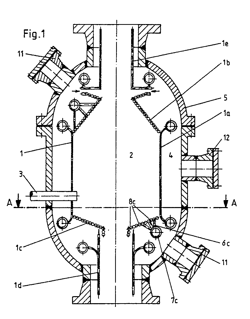
Description
Die Erfindung betrifft einen Druckbehälter, wie Druckreaktor, Druckabhitzekessel oder dgl., bestehend aus einem Druckmantel und innerhalb desselben angeordneter Wärmetauschfläche, die als Rohrwandkonstruktion ausgebildet und in einzelne Kühlkreisläufe mit separaten Kühlwasser-Zuführungsleitungen und Kühlwasser-Abführungsleitungen unterteilt ist.The invention relates to a pressure vessel, such as a pressure reactor, pressure waste heat boiler or the like, consisting of a pressure jacket and heat exchange surface arranged within the same, which is designed as a tube wall construction and is divided into individual cooling circuits with separate cooling water supply lines and cooling water discharge lines.
Da bei derartigen Einrichtungen Schäden an der Rohrwandkonstruktion, insbesondere aber an den Anschlußstellen der Kühlwasser-Zuführungsleitungen und Kühlwasser-Abführungsleitungen an die Rohre der einzelnen Kühlkreisläufe nicht auszuschließen sind, muß zu Reparaturzwecken eine Zugangsmöglichkeit zu allen Bereichen des Druckbehälterinneren vorgesehen werden.Since damage to the pipe wall construction, but especially at the connection points of the cooling water supply lines and cooling water discharge lines to the pipes of the individual cooling circuits cannot be ruled out in such devices, access to all areas of the pressure vessel interior must be provided for repair purposes.
Eine Möglichkeit, einen solchen Zugang zu schaffen, besteht darin, die Rohrwandkonstruktion mit Zu- und Abführungsleitungen komplett aus dem Druckmantel herauszuziehen. Die betreffenden Schadensstellen konnen dann außerhalb des Druckmantels problemlos bearbeitet werden. Nachteilig ist hierbei jedoch der vergleichsweise große Aufwand, der darin besteht, daß der Druckmantel zunächst geöffnet werden muß, worauf mittels einer eigens hierfür zu installierenden Hebe- und Transporteinrichtung die Rohrwandkonstruktion aus dem Druckmantel entfernt werden kann.One way to create such an access is to pull the pipe wall construction with supply and discharge lines completely out of the pressure jacket. The affected areas can then be easily processed outside the pressure jacket. The disadvantage here, however, is the comparatively great effort, which consists in the fact that the pressure jacket must first be opened, whereupon the tube wall construction can be removed from the pressure jacket by means of a lifting and transport device to be installed especially for this purpose.
Eine andere Möglichkeit ist die, Reparaturarbeiten im Inneren des Druckmantels auszuführen. Dabei ist zu unterscheiden zwischen Arbeiten im Innenraum der Rohrwandkonstruktion und Arbeiten im Raum zwischen Druckmantel und Rohrwandkonstruktion. Die erstgenannten Arbeiten können im allgemeinen ohne größere Schwierigkeiten durchgeführt werden, da der Innenraum in der Regel hinreichend groß bemessen ist und der Zugang dahin durch Mannlöcher im Druckmantel und Durchtritte in der Rohrwandkonstruktion gegeben ist. Anders sieht es dagegen für die Arbeiten im Raum zwischen Druckmantel und Rohrwandkonstruktion aus. Dort ist üblicherweise der Druckmantel so eng um die Rohrwandkonstruktion gelegt, daß ein Zugang zu diesem Raum und ein Aufenthalt darin zu Reparaturzwecken nicht möglich ist. Als Ausweg bliebe die Möglichkeit, den Raum zu vergrößern, d.h. den Durchmesser des Druckmantels größer zu wählen, was wiederum mit ganz beträchtlichen Mehrkosten verbunden wäre.Another possibility is to carry out repair work inside the pressure jacket. A distinction must be made between working in the interior of the pipe wall construction and working in the space between the pressure jacket and the pipe wall construction. The first-mentioned work can generally be carried out without major difficulties, since the interior is generally sufficiently large and access is provided through manholes in the pressure jacket and passages in the pipe wall construction. The situation is different for work in the space between the pressure jacket and the pipe wall construction. There the pressure jacket is usually placed so tightly around the pipe wall construction that access to this room and a stay in it for repair purposes is not possible. The way out would be to enlarge the room, i.e. to choose the diameter of the pressure jacket larger, which in turn would be associated with very considerable additional costs.
Der Erfindung liegt daher die Aufgabe zugrunde, den Druckbehälter der eingangs beschriebenen Gattung so auszubilden, daß ein Zugang zu allen reparaturanfälligen Bereichen ohne nennenswerten Mehraufwand möglich ist.The invention is therefore based on the object of designing the pressure vessel of the type described in the introduction in such a way that access to all areas susceptible to repair is possible without any significant additional outlay.
Erfindungsgemäß wird hierzu vorgeschlagen, daß die Anschlüsse der Kühlwasser-Zuführungsleitungen und Kühlwasser-Abführungsleitungen an die Rohre der einzelnen Kühlkreisläufe jeweils konzentriert in einem oder mehreren Bereichen der Rohrwandkonstruktion eines Kühlkreislaufes angeordnet sind.For this purpose, it is proposed according to the invention that the connections of the cooling water supply lines and cooling water discharge lines to the tubes of the individual cooling circuits are each concentrated in one or more areas of the tube wall construction of a cooling circuit.
Die Erfindung sieht ferner vor, daß die Anschlüsse der Kühlwasser-Zuführungsleitungen und Kühlwasser-Abführungsleitungen vom Innenraum der Rohrwandkonstruktion zu Reparaturzwecken durch Öffnungen zugänglich sind, die durch Heraustrennen eines Teiles der Rohrwandkonstruktion des betreffenden Kühlkreislaufes nahe dem Bereich der konzentrierten Anordnung der Anschlüsse gebildet wird.The invention further provides that the connections of the cooling water supply lines and cooling water discharge lines are accessible from the interior of the tube wall structure for repair purposes through openings which are formed by removing part of the tube wall structure of the cooling circuit in question near the area of the concentrated arrangement of the connections.
Schließlich sind im Druckmantel nahe den Bereichen der konzentrierten Anordnung der Anschlüsse der Kühlwasser-Zuführungsleitungen und Kühlwasser-Abführungsleitungen Inspektionsöffnungen vorgesehen.Finally, inspection openings are provided in the pressure jacket near the areas of the concentrated arrangement of the connections of the cooling water supply lines and cooling water discharge lines.
Einzelheiten der Erfindung werden im folgenden anhand der Zeichnung beschrieben, die als ein Anwendungsbeispiel einen Druckreaktor zur Vergasung von Kohlenstaub in der Schwebe in schematisch vereinfachter Form darstellt. Hierbei ist
- Fig. 1 ein senkrechter Schnitt durch den Druckreaktor und
- Fig. 2 ein waagerechter Schnitt nach der Linie A-A der Fig. 1.
- Fig. 1 is a vertical section through the pressure reactor and
- 2 is a horizontal section along the line AA of FIG. 1st
In Fig. 1 ist mit 1 die Rohrwandkonstruktion bezeichnet, deren Innenraum 2 der Vergasungsraum ist. In den Vergasungsraum münden mehrere Brenner 3, von denen in der Zeichnung nur einer dargestellt ist. Die Rohrwandkonstruktion 1 ist unter Belassung eines Ringraumes 4 von einem Druckmantel 5 umgeben.In Fig. 1, 1 designates the tube wall construction, the
Die Rohrwandkonstruktion 1 ist zusammengesetzt aus einzelnen Kühlkreisläufen 1a, 1b, 1c, 1d und 1e. Jeder dieser Kühlkreisläufe weist eine separate Kühlwasser-Zuführungsleitung und eine separate KühlwasserAbführungsleitung auf, die in der Zeichnung nur angedeutet ist. Am Beispiel des Kühlkreislaufes 1c ist die erfindungsgemäße Maßnahme veranschaulicht, wonach die Anschlüsse 6c der Kühlwasser-Zuführungsleitung 7c an die Rohre 8c konzentriert in einem engen Bereich, d.h. nahe beieinander,angeordnet sind. Die Anordnung ermöglicht es, in Nachbarbereichen, die keine Rohranschlüsse aufweisen, Teile der Rohrwandkonstruktion herauszutrennen, die in Fig. 2 mit 9 und 1o bezeichnet und strichpunktiert dargestellt sind. Nach Heraustrennen solcher Teile 9 bzw. 1o ist der Zugang zu den Anschlüssen 6c vom Innenraum 2 frei, und es können von hier aus nunmehr die notwendigen Reparaturarbeiten durchgeführt werden. Nach Beendigung der Reparaturarbeiten kann die zuvor freigelegte Öffnung in der Rohrwandkonstruktion entweder durch das herausgetrennte Teil oder ein entsprechend ausgebildetes neues Teil mittels Schweißung wieder verschlossen werden.The
Die Unterteilung der Rohrwandkonstruktion in einzelne Kühlkreisläufe ermöglicht ein schnelles Lokalisieren von Schadensstellen, da jeder Kühlkreislauf separat abgedrückt werden kann und damit der betreffende schadhafte Kühlkreislauf direkt ermittelt werden kann. Danach ist es möglich, mittels am Druckmantel 5 im Bereich konzentrierter Rohranschlusse vorgesehener Inspektionsöffnungen 11 durch Sichtkontakt oder durch Inspektionsgeräte die genaue Schadensstelle festzustellen.The subdivision of the pipe wall construction into individual cooling circuits enables damage to be localized quickly, since each cooling circuit can be pressed separately and the relevant defective cooling circuit can thus be determined directly. Thereafter, it is possible to determine the exact damage location by means of
Die Erfindung ermöglicht es ferner, in Bereichen mit hohem Verschleiß, wo keine Rohranschlüsse vorgesehen sind, Teile der Rohrwandkonstruktion herauszutrennen und durch neue Teile zu ersetzen.The invention also makes it possible to cut out parts of the pipe wall construction and replace them with new parts in areas with high wear, where no pipe connections are provided.
Mit 12 ist in Fig. 1 schließlich noch ein Mannloch im Druckmantel 5 bezeichnet, durch das sowie durch einen hier nicht eingezeichneten Durchtritt in der rohrwandkonstruktion der Zugang zum Innenraum 2 zwecks Durchführung dort erforderlicher Reparaturarbeiten gegeben ist.Finally, 12 in FIG. 1 also designates a manhole in the
Claims (3)
Applications Claiming Priority (2)
| Application Number | Priority Date | Filing Date | Title |
|---|---|---|---|
| DE19873742644 DE3742644A1 (en) | 1987-12-16 | 1987-12-16 | PRESSURE TANK, LIKE PRESSURE REACTOR, PRESSURE HEATER, OR THE LIKE |
| DE3742644 | 1987-12-16 |
Publications (4)
| Publication Number | Publication Date |
|---|---|
| EP0321684A2 true EP0321684A2 (en) | 1989-06-28 |
| EP0321684A3 EP0321684A3 (en) | 1989-07-05 |
| EP0321684B1 EP0321684B1 (en) | 1990-10-03 |
| EP0321684B2 EP0321684B2 (en) | 1993-03-17 |
Family
ID=6342746
Family Applications (1)
| Application Number | Title | Priority Date | Filing Date |
|---|---|---|---|
| EP88118293A Expired - Lifetime EP0321684B2 (en) | 1987-12-16 | 1988-11-03 | Pressure container, such as a pressure reactor or pressure waste heat boiler |
Country Status (7)
| Country | Link |
|---|---|
| EP (1) | EP0321684B2 (en) |
| JP (1) | JP2685552B2 (en) |
| DD (1) | DD283450A5 (en) |
| DE (2) | DE3742644A1 (en) |
| ES (1) | ES2018066T5 (en) |
| PL (1) | PL275473A1 (en) |
| ZA (2) | ZA886465B (en) |
Cited By (4)
| Publication number | Priority date | Publication date | Assignee | Title |
|---|---|---|---|---|
| EP0459023A1 (en) * | 1990-05-29 | 1991-12-04 | Deutsche Babcock Energie- Und Umwelttechnik Aktiengesellschaft | Apparatus for gasifying carbon containing materials |
| WO1994016038A1 (en) * | 1992-12-30 | 1994-07-21 | Combustion Engineering, Inc. | Circular slag tap for a gasifier |
| TWI461523B (en) * | 2008-07-24 | 2014-11-21 | Uhde Gmbh | Method and reactor for gasification of powdery, solid or liquid fuels such as coal, pet coke, oil, bitumen or the like |
| RU2763631C1 (en) * | 2021-06-28 | 2021-12-30 | Публичное акционерное общество «Татнефть» имени В.Д. Шашина | Method for withdrawal for repair of a steam horizontal water-tube boiler |
Family Cites Families (2)
| Publication number | Priority date | Publication date | Assignee | Title |
|---|---|---|---|---|
| US2547589A (en) * | 1947-07-02 | 1951-04-03 | Comb Eng Superheater Inc | Apparatus for extracting heat from gases under pressure |
| DE3009851C2 (en) * | 1980-03-14 | 1983-09-15 | Karrena GmbH, 4000 Düsseldorf | Reactor containers, in particular for gasifying fossil fuels |
-
1987
- 1987-12-16 DE DE19873742644 patent/DE3742644A1/en not_active Withdrawn
-
1988
- 1988-08-31 ZA ZA886465A patent/ZA886465B/en unknown
- 1988-10-25 PL PL27547388A patent/PL275473A1/en unknown
- 1988-11-03 EP EP88118293A patent/EP0321684B2/en not_active Expired - Lifetime
- 1988-11-03 DE DE8888118293T patent/DE3860753D1/en not_active Expired - Fee Related
- 1988-11-03 ES ES88118293T patent/ES2018066T5/en not_active Expired - Lifetime
- 1988-12-13 DD DD88323080A patent/DD283450A5/en not_active IP Right Cessation
- 1988-12-14 ZA ZA889348A patent/ZA889348B/en unknown
- 1988-12-16 JP JP63316584A patent/JP2685552B2/en not_active Expired - Lifetime
Cited By (4)
| Publication number | Priority date | Publication date | Assignee | Title |
|---|---|---|---|---|
| EP0459023A1 (en) * | 1990-05-29 | 1991-12-04 | Deutsche Babcock Energie- Und Umwelttechnik Aktiengesellschaft | Apparatus for gasifying carbon containing materials |
| WO1994016038A1 (en) * | 1992-12-30 | 1994-07-21 | Combustion Engineering, Inc. | Circular slag tap for a gasifier |
| TWI461523B (en) * | 2008-07-24 | 2014-11-21 | Uhde Gmbh | Method and reactor for gasification of powdery, solid or liquid fuels such as coal, pet coke, oil, bitumen or the like |
| RU2763631C1 (en) * | 2021-06-28 | 2021-12-30 | Публичное акционерное общество «Татнефть» имени В.Д. Шашина | Method for withdrawal for repair of a steam horizontal water-tube boiler |
Also Published As
| Publication number | Publication date |
|---|---|
| ES2018066B3 (en) | 1991-03-16 |
| DE3860753D1 (en) | 1990-11-08 |
| ZA886465B (en) | 1989-05-30 |
| JPH01238771A (en) | 1989-09-22 |
| ZA889348B (en) | 1989-08-30 |
| ES2018066T5 (en) | 1995-08-01 |
| JP2685552B2 (en) | 1997-12-03 |
| PL275473A1 (en) | 1989-06-26 |
| DD283450A5 (en) | 1990-10-10 |
| DE3742644A1 (en) | 1989-06-29 |
| EP0321684B2 (en) | 1993-03-17 |
| EP0321684A3 (en) | 1989-07-05 |
| EP0321684B1 (en) | 1990-10-03 |
Similar Documents
| Publication | Publication Date | Title |
|---|---|---|
| EP0321684B1 (en) | Pressure container, such as a pressure reactor or pressure waste heat boiler | |
| DE3126169A1 (en) | DEVICE FOR RINSING AND RECOVERY OF SLUDGE DEPOSED ON THE TUBE PLATE OF A STEAM GENERATOR | |
| DE4302330C1 (en) | Method and device for shielding the radiation emitted by the probes of the inner core instrumentation of a water-cooled nuclear reactor | |
| DE4437180A1 (en) | Method for operating a head box of a paper or board machine | |
| DE19507172A1 (en) | Treatment plant for drilling mud built into transport containers for easy relocation | |
| DE2258518A1 (en) | DETACHABLE UPPER SHIELD FOR THE CORE OF A NUCLEAR REACTOR | |
| CH678371A5 (en) | ||
| DE10163612A1 (en) | filtration device | |
| DE19547652C1 (en) | Arrangement of coolant gas pipes for a pebble bed nuclear reactor | |
| DE112018000941T5 (en) | Fuel gas heater, support structure for fuel gas heater and method of cleaning the fuel gas heater | |
| DE3142674A1 (en) | Tank container | |
| DE19846591A1 (en) | Device and method for flushing around rod elements | |
| EP1135203B1 (en) | Device for providing a loose flange of a manhole opening or the like, especially for fluidized reactors | |
| AT406833B (en) | ADDITIONAL DEVICE FOR A DEVICE FOR CLEANING METAL BARRELS, IN PARTICULAR BEER BARRELS | |
| DE8708850U1 (en) | Heat exchanger | |
| EP0344094A1 (en) | Flash tank for hot fluids under pressure | |
| DE3731908C2 (en) | ||
| DE1807422A1 (en) | Nuclear reactor | |
| DE202009007971U1 (en) | Device for moistening a bulk material | |
| DE3813864A1 (en) | Apparatus, in particular for producing synthesis gas in a reformer | |
| DE4221130A1 (en) | Tube bundle type liq. evaporator - useful for steam generation or hot gas cooling | |
| CH492178A (en) | Sectional boiler | |
| DE3324857A1 (en) | Apparatus for carrying out a thermal product treatment in a fluidised bed, especially a fluidised bed furnace | |
| DE1644948A1 (en) | Device for processing old oil | |
| DE3613963C2 (en) |
Legal Events
| Date | Code | Title | Description |
|---|---|---|---|
| PUAI | Public reference made under article 153(3) epc to a published international application that has entered the european phase |
Free format text: ORIGINAL CODE: 0009012 |
|
| PUAL | Search report despatched |
Free format text: ORIGINAL CODE: 0009013 |
|
| AK | Designated contracting states |
Kind code of ref document: A2 Designated state(s): DE ES GB IT NL |
|
| AK | Designated contracting states |
Kind code of ref document: A3 Designated state(s): DE ES GB IT NL |
|
| 17P | Request for examination filed |
Effective date: 19890616 |
|
| 17Q | First examination report despatched |
Effective date: 19900301 |
|
| GRAA | (expected) grant |
Free format text: ORIGINAL CODE: 0009210 |
|
| AK | Designated contracting states |
Kind code of ref document: B1 Designated state(s): DE ES GB IT NL |
|
| ITF | It: translation for a ep patent filed | ||
| GBT | Gb: translation of ep patent filed (gb section 77(6)(a)/1977) | ||
| REF | Corresponds to: |
Ref document number: 3860753 Country of ref document: DE Date of ref document: 19901108 |
|
| PLBI | Opposition filed |
Free format text: ORIGINAL CODE: 0009260 |
|
| 26 | Opposition filed |
Opponent name: DEUTSCHE BABCOCK AKTIENGESELLSCHAFT Effective date: 19910625 |
|
| NLR1 | Nl: opposition has been filed with the epo |
Opponent name: DEUTSCHE BABCOCK AG |
|
| ITTA | It: last paid annual fee | ||
| PUAH | Patent maintained in amended form |
Free format text: ORIGINAL CODE: 0009272 |
|
| STAA | Information on the status of an ep patent application or granted ep patent |
Free format text: STATUS: PATENT MAINTAINED AS AMENDED |
|
| 27A | Patent maintained in amended form |
Effective date: 19930317 |
|
| AK | Designated contracting states |
Kind code of ref document: B2 Designated state(s): DE ES GB IT NL |
|
| GBTA | Gb: translation of amended ep patent filed (gb section 77(6)(b)/1977) |
Effective date: 19930303 |
|
| ITF | It: translation for a ep patent filed | ||
| NLR2 | Nl: decision of opposition | ||
| NLR3 | Nl: receipt of modified translations in the netherlands language after an opposition procedure | ||
| REG | Reference to a national code |
Ref country code: ES Ref legal event code: DC2A Kind code of ref document: T5 Effective date: 19950801 |
|
| PGFP | Annual fee paid to national office [announced via postgrant information from national office to epo] |
Ref country code: ES Payment date: 19951120 Year of fee payment: 8 |
|
| PGFP | Annual fee paid to national office [announced via postgrant information from national office to epo] |
Ref country code: GB Payment date: 19961014 Year of fee payment: 9 |
|
| PGFP | Annual fee paid to national office [announced via postgrant information from national office to epo] |
Ref country code: NL Payment date: 19961024 Year of fee payment: 9 Ref country code: DE Payment date: 19961024 Year of fee payment: 9 |
|
| PG25 | Lapsed in a contracting state [announced via postgrant information from national office to epo] |
Ref country code: GB Free format text: LAPSE BECAUSE OF NON-PAYMENT OF DUE FEES Effective date: 19971103 |
|
| PG25 | Lapsed in a contracting state [announced via postgrant information from national office to epo] |
Ref country code: ES Free format text: LAPSE BECAUSE OF NON-PAYMENT OF DUE FEES Effective date: 19971104 |
|
| PG25 | Lapsed in a contracting state [announced via postgrant information from national office to epo] |
Ref country code: NL Free format text: LAPSE BECAUSE OF NON-PAYMENT OF DUE FEES Effective date: 19980601 |
|
| GBPC | Gb: european patent ceased through non-payment of renewal fee |
Effective date: 19971103 |
|
| PG25 | Lapsed in a contracting state [announced via postgrant information from national office to epo] |
Ref country code: DE Free format text: LAPSE BECAUSE OF NON-PAYMENT OF DUE FEES Effective date: 19980801 |
|
| NLV4 | Nl: lapsed or anulled due to non-payment of the annual fee |
Effective date: 19980601 |
|
| REG | Reference to a national code |
Ref country code: ES Ref legal event code: FD2A Effective date: 19981212 |
|
| PG25 | Lapsed in a contracting state [announced via postgrant information from national office to epo] |
Ref country code: IT Free format text: LAPSE BECAUSE OF NON-PAYMENT OF DUE FEES;WARNING: LAPSES OF ITALIAN PATENTS WITH EFFECTIVE DATE BEFORE 2007 MAY HAVE OCCURRED AT ANY TIME BEFORE 2007. THE CORRECT EFFECTIVE DATE MAY BE DIFFERENT FROM THE ONE RECORDED. Effective date: 20051103 |