EP0321644B1 - Fire and smoke stop for wall openings - Google Patents
Fire and smoke stop for wall openings Download PDFInfo
- Publication number
- EP0321644B1 EP0321644B1 EP88109292A EP88109292A EP0321644B1 EP 0321644 B1 EP0321644 B1 EP 0321644B1 EP 88109292 A EP88109292 A EP 88109292A EP 88109292 A EP88109292 A EP 88109292A EP 0321644 B1 EP0321644 B1 EP 0321644B1
- Authority
- EP
- European Patent Office
- Prior art keywords
- moulding
- closure according
- wall
- opening
- fire
- Prior art date
- Legal status (The legal status is an assumption and is not a legal conclusion. Google has not performed a legal analysis and makes no representation as to the accuracy of the status listed.)
- Expired - Lifetime
Links
Images
Classifications
-
- A—HUMAN NECESSITIES
- A62—LIFE-SAVING; FIRE-FIGHTING
- A62C—FIRE-FIGHTING
- A62C2/00—Fire prevention or containment
- A62C2/06—Physical fire-barriers
-
- F—MECHANICAL ENGINEERING; LIGHTING; HEATING; WEAPONS; BLASTING
- F16—ENGINEERING ELEMENTS AND UNITS; GENERAL MEASURES FOR PRODUCING AND MAINTAINING EFFECTIVE FUNCTIONING OF MACHINES OR INSTALLATIONS; THERMAL INSULATION IN GENERAL
- F16L—PIPES; JOINTS OR FITTINGS FOR PIPES; SUPPORTS FOR PIPES, CABLES OR PROTECTIVE TUBING; MEANS FOR THERMAL INSULATION IN GENERAL
- F16L5/00—Devices for use where pipes, cables or protective tubing pass through walls or partitions
- F16L5/02—Sealing
- F16L5/04—Sealing to form a firebreak device
Definitions
- the invention relates to a fire and smoke-tight closure for openings in walls, ceilings and the like.
- the object of the invention is to provide a fire and smoke-tight closure for openings in fire protection walls and ceilings, which can be installed in a simple manner immediately after the creation of these walls and ensures a fire-proof seal of the openings.
- the fire protection plug according to the invention is expediently formed in one piece and shaped in such a way that it is pushed into the circular or oval wall opening by hand, and due to a slight oversize and its slightly conical shape, it engages with a predetermined pressure on the inner wall of the opening after insertion .
- the molded body consists of a fire protection foam which carbonizes at temperatures of approximately 300 ° C. and / or under the influence of flame with a multiple increase in volume.
- this foam Due to the consistency of this foam, it is possible to close the wall openings immediately after the walls have been manufactured to prevent air or steam from penetrating and only to cut one or more through openings into these moldings during installation, the diameter of which is that of the openings to be passed through Lines and cables are precisely adapted.
- the outer shape of these fire protection plugs can be easily cut on site so that the openings are completely closed and particularly sensitive rooms such as computer rooms, laboratories, production rooms for highly sensitive articles can be securely closed at a very early stage.
- the ease of processing of the molding material also enables the outer surface of the molding to be positioned exactly flush with the adjacent wall surfaces.
- the fire protection plug according to the invention can also be constructed in multiple layers and have inlays or jackets.
- the fire protection plug I shown in FIGS. 1a, 1b has a slightly conical shape with a smooth side wall 1, a flat circular base surface 2 and an upwardly curved end surface 3.
- the material is a fine-pored two-component foam which is formed by foaming in hollow molds adjustable hardness and density.
- foams are used as intumescent materials to close gaps and cracks known in masonry.
- a fire-resistant carbon foam is formed that takes up several times the original volume and establishes the fire-proof properties.
- foams are also known as intumescent materials, for example under the name "Fomox PA" or "Fomox PE” (registered trademark).
- the fire protection plugs I, II are pressed into a breakthrough 4 of a concrete wall 5 from the outside, the smaller, flat inner surface pointing inwards when, as shown, two plugs are pressed into a wall breakthrough 4. Due to the material used and the conical shape, each plug is compressed at least in its edge area when inserted into the opening 4, the inherent elasticity of the foam causing a large-area pressure on the possibly uneven inner surfaces of the opening and thus a secure seal against flames and flue gases.
- a through hole 6 can be made in both plugs by means of a suitable tool, for example a core cutter, through which electrical cables, pipelines or the like can then be passed.
- the lines or cables are securely supported and held in each of the plugs. If the wall openings are square or rectangular, the respective plug at the operating point can be used with a knife or the like. be cut to size, whereby a certain excess should be maintained in order to ensure the large pressure on the uneven side surfaces of the wall opening.
- the fire protection plug can also have flat end faces and / or square or oval cross sections, and can consist of several layers of different materials with and without inlays, e.g. Asbestos fibers, rock wool, or the like.
- a molded body into the wall openings from both sides and to fill any cavities that may remain between the two molded bodies with a liquid-injected multi-component foam that creates a firm adhesive connection to the surfaces of the wall openings and any lines that may have been drawn in .
- This material which is only foamed on site, should expediently have the same fire protection properties and / or composition as the molded articles. The pressure developing during foaming ensures a particularly secure seal.
- One or more fire protection plugs or molded bodies can also be fixed in the wall opening by means of a fire protection adhesive which is applied to the outer surfaces of the plug before insertion.
Abstract
Description
Die Erfindung betrifft einen feuer- und rauchdichten Verschluß für Durchbrüche in Wänden, Decken u.dgl.The invention relates to a fire and smoke-tight closure for openings in walls, ceilings and the like.
Bei der Herstellung von feuersicheren Räumen sind die für Kabel, Rohre, usw. notwendigen Wanddurchbrüche problematisch, weil sie bisher erst nach Fertigstellung der gesamten Installation, d.h. nach dem Verlegen der elektrischen Kabel und Rohrleitungen sicher verschlossen werden konnten. Bis zu diesem Zeitpunkt blieben die Wanddurchbrüche entweder offen oder sie wurden nur vorläufig durch zugeschnittene Asbestplatten und/oder Steinwolle verschlossen. Zum Hindurchführen der Kabel und Leitungen müssen diese Verschlüsse wieder entfernt werden, wobei dann nach dem Hindurchführen der Leitungen und Kabel die Wanddurchbrüche durch Brandschutz-Mörtel, Steinwolle und/oder Asbesteinlagen endgültig verschlossen werden. In den Zeiten zwischen der Fertigstellung des Rohbaus und dem Abschluß der Installationsarbeiten ist ein ausreichender Brandschutz somit nicht gegeben. Bei der Herstellung von technischen Sonderräumen, wie den sog. Reinluft-Räumen, können bis zur Beendigung der Installationsarbeiten bzw. bis zur Inbetriebnahme der darin aufgestellten Aggregate Staub, Wasserdampf, usw. durch die nur unvollständig verschlossenen Durchbrüche hindurchtreten, was dann Schwierigkeiten bei der Inbetriebnahme der Aggregate und ggf. beim Erhalt der Reinluft-Bedingungen bereitet.In the manufacture of fire-proof rooms, the wall openings necessary for cables, pipes, etc. are problematic because, until now, they could only be securely closed after the entire installation had been completed, ie after the electrical cables and pipes had been laid. Up to this point, the wall openings either remained open or were only temporarily closed with cut asbestos panels and / or rock wool. To carry the cables and lines through, these closures must be removed again, the wall openings then being finally sealed with fire protection mortar, rock wool and / or asbestos inserts after the lines and cables have been passed through. Adequate fire protection is therefore not ensured in the times between the completion of the shell and the completion of the installation work. In the production of special technical rooms, such as the so-called clean air rooms, the installation work or until commissioning of the units installed therein, dust, water vapor, etc. pass through the incompletely closed openings, which then causes difficulties in commissioning the units and possibly in maintaining the clean air conditions.
Aus der EP-A-0 153 564 A3 ist eine feuer- und rauchdichte Abdichtung von Wanddurchbrüchen bei Bauwerken bekannt, bei welcher zwei thermisch expandierende Massen von unterschiedlichem Blähdruck und Blähtemperatur in zumindest zwei Schichten in den Durchbruch eingebracht werden. Im Brandfall schäumt die Masse der äußeren Schicht zuerst auf und dichtet aufgrund ihres höheren Blähdrucks den Innenraum des Durchbruchs ab. Erst bei längerer Hitzeeinwirkung erfolgt das Aufschäumen der Masse der inneren Schicht und damit die vollständige Ausfüllung der Freiräume des Durchbruchs. Die Herstellung dieser Abdichtung ist jedoch arbeits- und zeitaufwendig, weil die einzelnen Schichten direkt vor Ort aus streichfähigen Massen oder aus Laminat sorgfältig aufgebaut werden müssen, was ausgebildetes Personal und ggf. den Einsatz zusätzlicher Hilfsmittel erfordert. Das nachträgliche Einschneiden für Durchgangsöffnungen zur Aufnahme von später installierten Leitungen, Rohren od. dgl. ist nicht ohne weiteres möglich.From EP-A-0 153 564 A3 a fire and smoke-tight seal of wall openings in buildings is known, in which two thermally expanding masses of different expansion pressure and expansion temperature are introduced into the opening in at least two layers. In the event of a fire, the mass of the outer layer first foams and seals the interior of the opening due to its higher inflation pressure. The foam of the mass of the inner layer and thus the complete filling of the free space of the breakthrough takes place only after prolonged exposure to heat. However, the production of this seal is labor-intensive and time-consuming because the individual layers have to be carefully built up directly on site from spreadable materials or from laminate, which requires trained personnel and possibly the use of additional aids. Subsequent cutting for through openings to accommodate later installed lines, pipes or the like is not readily possible.
Aufgabe der Erfindung ist es, einen feuer- und rauchdichten Verschluß für Durchbrüche in Brandschutz-Wänden und -Decken zu schaffen, der auf einfache Weise unmittelbar nach der Erstellung dieser Wände eingebaut werden kann und eine brandsichere Abdichtung der Durchbrüche gewährleistet.The object of the invention is to provide a fire and smoke-tight closure for openings in fire protection walls and ceilings, which can be installed in a simple manner immediately after the creation of these walls and ensures a fire-proof seal of the openings.
Erfindungsgemäß wird diese Aufgabe durch die kennzeichnenden Merkmale des Anspruchs 1 gelöst.According to the invention, this object is achieved by the characterizing features of claim 1.
Der erfindungsgemäße Brandschutzstopfen ist zweckmäßigerweise einstückig ausgebildet und so geformt, daß er in den kreisrunden oder auch ovalen Wanddurchbruch von Hand eingeschoben wird, wobei er aufgrund eines geringen Übermaßes und seiner leicht konischen Form sich nach dem Einschieben mit einem vorgegebenen Druck an die Innenwandung des Durchbruchs anlegt. Gemäß einer zweckmäßigen Ausgestaltung der Erfindung besteht der Formkörper aus einem Brandschutz-Schaumstoff, der bei Temperaturen von ca. 300 °C und/oder bei Flammeneinwirkung unter mehrfacher Volumenvergrößerung karbonisiert. Aufgrund der Konsistenz dieses Schaumstoffs ist es möglich, die Wanddurchbrüche unmittelbar nach Herstellung der Wände gegen Luft- bzw. Dampfdurchtritt zu verschließen und erst während der Installation in diese Formkörper einen oder mehrere Durchgangsöffnungen einzuschneiden, deren Durchmesser an die der hindurchzuführenden Leitungen und Kabel genau angepaßt ist. Darüber hinaus läßt sich auch die Außenform dieser Brandschutzstopfen vor Ort auf einfache Weise zuschneiden, so daß die Durchbrüche vollständig verschlossen und auch besonders empfindliche Räumlichkeiten, wie Computerräume, Laborräume, Produktionsräume für hochempfindliche Artikel, bereits in einem sehr frühen Stadium sicher verschlossen werden können. Die leichte Bearbeitbarkeit des Formkörper-Materials ermöglicht auch die genau bündige Lage der Außenfläche des Formkörpers zu den angrenzenden Wandflächen.The fire protection plug according to the invention is expediently formed in one piece and shaped in such a way that it is pushed into the circular or oval wall opening by hand, and due to a slight oversize and its slightly conical shape, it engages with a predetermined pressure on the inner wall of the opening after insertion . According to an expedient embodiment of the invention, the molded body consists of a fire protection foam which carbonizes at temperatures of approximately 300 ° C. and / or under the influence of flame with a multiple increase in volume. Due to the consistency of this foam, it is possible to close the wall openings immediately after the walls have been manufactured to prevent air or steam from penetrating and only to cut one or more through openings into these moldings during installation, the diameter of which is that of the openings to be passed through Lines and cables are precisely adapted. In addition, the outer shape of these fire protection plugs can be easily cut on site so that the openings are completely closed and particularly sensitive rooms such as computer rooms, laboratories, production rooms for highly sensitive articles can be securely closed at a very early stage. The ease of processing of the molding material also enables the outer surface of the molding to be positioned exactly flush with the adjacent wall surfaces.
Je nach speziellen Anforderungen und die Zweckbestimmung der abzudichtenden Räumlichkeiten kann der erfindungsgemäße Brandschutzstopfen auch mehrschichtig aufgebaut sein und Einlagen bzw. Ummantelungen aufweisen.Depending on the special requirements and the intended use of the rooms to be sealed, the fire protection plug according to the invention can also be constructed in multiple layers and have inlays or jackets.
Im folgenden wird ein Ausführungsbeispiel des erfindungsgemäßen Brandschutzstopfens anhand der Zeichnung im einzelnen beschrieben. Es zeigen:
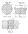
- Fig. 1a, 1b
- einen Brandschutzstopfen im Querschnitt und im Axialschnitt;
- Fig. 2
- den Verschluß einer Wanddurchbrechung durch zwei Brandschutzstopfen.
- 1a, 1b
- a fire protection plug in cross-section and in axial section;
- Fig. 2
- the closure of a wall opening by two fire plugs.
Der in den Fig. 1a, 1b dargestellte Brandschutzstopfen I hat eine leicht konische Form mit einer glatten Seitenwand 1, einer ebenen kreisförmigen Bodenfläche 2 und einer nach oben gewölbten Stirnfläche 3. Das Material ist ein feinporiger Zweikomponenten-Schaumstoff, der durch Aufschäumen in Hohlformen mit einstellbarer Härte und Raumgewicht hergestellt wird. Derartige Schaumstoffe sind als Intumeszenzmaterialien zum Verschließen von Spalten und Rissen im Mauerwerk bekannt. Bei Beflammung bildet sich ein feuerwiderstandsfähiger Kohlenstoffschaum, der das Mehrfache des ursprünglichen Volumens einnimmt und die feuersicheren Eigenschaften begründet. Derartige Schaumstoffe sind auch als Intumeszenzmaterialien, z.B. unter der Bezeichnung "Fomox PA" bzw. "Fomox PE" (eingetragenes Warenzeichen) bekannt.The fire protection plug I shown in FIGS. 1a, 1b has a slightly conical shape with a smooth side wall 1, a flat circular base surface 2 and an upwardly
Wie aus Fig. 2 ersichtlich, werden die Brandschutzstopfen I, II in einen Durchbruch 4 einer Betonwand 5 von außen eingedrückt, wobei die kleinere ebene Innenfläche nach innen weist, wenn - wie dargestellt - jeweils zwei Stopfen in einen Wanddurchbruch 4 eingedrückt werden. Aufgrund des verwendeten Materials und der konischen Form wird jeder Stopfen beim Einschieben in den Durchbruch 4 zumindest in seinem Randbereich zusammengedrückt, wobei die Eigenelastizität des Schaumstoffes einen großflächigen Andruck an die ggf. unebenen Innenflächen des Durchbruchs und damit eine sichere Abdichtung gegen Flammen und Rauchgase bewirkt. Wie in Fig. 2 ferner dargestellt, kann durch ein geeignetes Werkzeug, z.B. einen Kernschneider, eine durchgehende Bohrung 6 in beiden Stopfen hergestellt werden, durch die dann elektrische Kabel, Rohrleitungen, od.dgl., hindurchgeführt werden können. Aufgrund der Druckanlage der beiden Stopfen an den Wänden des Durchbruchs 4 erfolgt eine sichere Abstützung und Halterung der Leitungen bzw. Kabel in jedem der Stopfen. Sollten die Mauerdurchbrüche viereckig oder rechtwinklig sein, kann der jeweilige Stopfen am Betriebspunkt mit einem Messer od.dgl. zurechtgeschnitten werden, wobei ein gewisses Übermaß eingehalten werden sollte, um den großflächigen Andruck an die unebenen Seitenflächen des Mauerdurchbruchs zu gewährleisten.As can be seen from FIG. 2, the fire protection plugs I, II are pressed into a breakthrough 4 of a
Die Erfindung ist nicht auf das dargestellte Ausführungsbeispiel beschränkt. Vielmehr kann der Brandschutzstopfen auch ebene Stirnflächen und/oder eckige oder ovale Querschnitte haben sowie aus mehreren Schichten unterschiedlicher Materialien mit und ohne Einlagen aus z.B. Asbestfasern, Steinwolle, od.dgl., aufgebaut sein.The invention is not restricted to the exemplary embodiment shown. Rather, the fire protection plug can also have flat end faces and / or square or oval cross sections, and can consist of several layers of different materials with and without inlays, e.g. Asbestos fibers, rock wool, or the like.
Ferner ist es möglich, in die Wanddurchbrüche von beiden Seiten aus je einen Formkörper einzupressen und die ggf. zwischen beiden Formkörpern verbleibenden Hohlräume mit einem flüssig injiziertem Mehrkomponenten-Schaumstoff auszufüllen, der eine feste Klebeverbindung zu den Oberflächen der Wanddurchbrüche und der ggf. eingezogenen Leitungen herstellt. Dieses erst vor Ort ausgeschäumte Material sollte zweckmäßig die gleichen Brandschutzeigenschaften und/oder Zusammensetzung wie die Formkörper haben. Der sich beim Ausschäumen entwickelnde Druck sorgt dabei für eine besonders sichere Abdichtung. Die Festlegung eines oder mehrerer Brandschutzstopfen bzw. Formkörper im Wanddurchbruch kann auch durch einen Brandschutzkleber erfolgen, der vor dem Einsetzen auf die Mantelflächen des Stopfens aufgebracht wird.Furthermore, it is possible to press a molded body into the wall openings from both sides and to fill any cavities that may remain between the two molded bodies with a liquid-injected multi-component foam that creates a firm adhesive connection to the surfaces of the wall openings and any lines that may have been drawn in . This material, which is only foamed on site, should expediently have the same fire protection properties and / or composition as the molded articles. The pressure developing during foaming ensures a particularly secure seal. One or more fire protection plugs or molded bodies can also be fixed in the wall opening by means of a fire protection adhesive which is applied to the outer surfaces of the plug before insertion.
Claims (9)
- A fire-proof and smoke-proof closure for openings in walls, ceilings or the like, consisting of an intumescent material introduced into and filling the free spaces of the opening, such material carbonising with an increase in volume when subjected to the action of flames or heat, characterised by at least one moulding formed as a prefabricated conical plug (I; II) from a flexibly deformable and cuttable two-component foam material which in cross-section has an oversize in comparison with the opening and, when inserted, bears by its side walls against the inner wall of the opening at a predetermined pressure.
- A closure according to claim 1, characterised in that the moulding is of multi-layer construction.
- A closure according to claim 1 or 2, characterised in that inlays are embedded in the moulding.
- A closure according to any one of claims 1 to 3, characterised in that the moulding has a flat base (2), a smooth peripheral side wall (1) and a curved end face (3).
- A closure according to any one of claims 1 to 4, characterised in that the moulding (1, 2) has a circular, oval or polygonal cross-section.
- A closure according to any one of claims 1 to 5, characterised in that continuous bores (6) are provided in the moulding for the sealing-tight accommodation of pipes, conduits, cables or the like.
- A closure according to any one of claims 1 to 6, characterised in that cavities are provided in the moulding.
- A closure according to any one of claims 1 to 7, characterised in that the mouldings (I; II) are fixed in the wall openings (4) by means of a fire protection adhesive.
- A closure according to any one of claims 1 to 7, characterised in that the mouldings (I; II) are fixed in the wall openings (4) by the foaming of a multi-component foam material injected in the liquid state into the remaining free spaces, such foam material having approximately the same composition and/or properties as the material of the moulding and completely filling any cavities between the wall opening and the associated moulding.
Priority Applications (1)
| Application Number | Priority Date | Filing Date | Title |
|---|---|---|---|
| AT88109292T ATE67807T1 (en) | 1987-12-23 | 1988-06-10 | FIRE AND SMOKE TIGHT CLOSURE FOR WALL OPENINGS. |
Applications Claiming Priority (2)
| Application Number | Priority Date | Filing Date | Title |
|---|---|---|---|
| DE8716909U | 1987-12-23 | ||
| DE8716909U DE8716909U1 (en) | 1987-12-23 | 1987-12-23 |
Publications (2)
| Publication Number | Publication Date |
|---|---|
| EP0321644A1 EP0321644A1 (en) | 1989-06-28 |
| EP0321644B1 true EP0321644B1 (en) | 1991-09-25 |
Family
ID=6815426
Family Applications (1)
| Application Number | Title | Priority Date | Filing Date |
|---|---|---|---|
| EP88109292A Expired - Lifetime EP0321644B1 (en) | 1987-12-23 | 1988-06-10 | Fire and smoke stop for wall openings |
Country Status (4)
| Country | Link |
|---|---|
| EP (1) | EP0321644B1 (en) |
| AT (1) | ATE67807T1 (en) |
| DE (2) | DE8716909U1 (en) |
| ES (1) | ES2026967T3 (en) |
Families Citing this family (2)
| Publication number | Priority date | Publication date | Assignee | Title |
|---|---|---|---|---|
| DE3918892C1 (en) * | 1989-06-09 | 1990-11-29 | Schaum-Chemie Wilhelm Bauer Gmbh & Co Kg, 4300 Essen, De | Fire-resistant closure in wall - fits closely round pips and cables and incorporates inorganic foam layer |
| DE202004004125U1 (en) * | 2004-03-15 | 2004-06-17 | Franz Viegener Ii Gmbh & Co. Kg | drain body |
Family Cites Families (8)
| Publication number | Priority date | Publication date | Assignee | Title |
|---|---|---|---|---|
| SE412795B (en) * | 1978-09-15 | 1980-03-17 | Studsvik Energiteknik Ab | PROCEDURES AND MEASURES FOR FIREFIGHTING A PIPE THROUGH |
| DE2847923A1 (en) * | 1978-11-04 | 1980-05-14 | Bayer Ag | FLAME-RESISTANT FOAMABLE MOLDS |
| US4363199A (en) * | 1980-05-05 | 1982-12-14 | Kennecott Corporation | Fire resistant sealing system for holes in fire resistant building partitions |
| DE8014157U1 (en) * | 1980-05-24 | 1980-08-28 | Herberts Gmbh, 5600 Wuppertal | Closure piece for building wall or ceiling openings |
| IE822972L (en) * | 1982-12-23 | 1984-06-23 | Attwell Ronald Leslie | Fire stop flue collar |
| DE3302416A1 (en) * | 1983-01-26 | 1984-07-26 | Bayer Ag, 5090 Leverkusen | CONSTRUCTION ELEMENTS WITH INTUMESCENT CHARACTERISTICS |
| DE3303702A1 (en) * | 1983-02-01 | 1984-08-02 | Bayer Ag, 5090 Leverkusen | Intumescent compositions |
| DE3404221A1 (en) * | 1984-02-07 | 1985-08-08 | Lentia GmbH Chem. u. pharm. Erzeugnisse - Industriebedarf, 8000 München | METHOD FOR SEALING OPENINGS IN COMPONENTS IN THE EVENT OF FIRE |
-
1987
- 1987-12-23 DE DE8716909U patent/DE8716909U1/de not_active Expired
-
1988
- 1988-06-10 ES ES198888109292T patent/ES2026967T3/en not_active Expired - Lifetime
- 1988-06-10 AT AT88109292T patent/ATE67807T1/en not_active IP Right Cessation
- 1988-06-10 EP EP88109292A patent/EP0321644B1/en not_active Expired - Lifetime
- 1988-06-10 DE DE8888109292T patent/DE3865189D1/en not_active Expired - Lifetime
Also Published As
| Publication number | Publication date |
|---|---|
| ATE67807T1 (en) | 1991-10-15 |
| ES2026967T3 (en) | 1992-05-16 |
| EP0321644A1 (en) | 1989-06-28 |
| DE3865189D1 (en) | 1991-10-31 |
| DE8716909U1 (en) | 1988-02-25 |
Similar Documents
| Publication | Publication Date | Title |
|---|---|---|
| EP2570157B1 (en) | Fire retardant element | |
| DE4113375C2 (en) | ||
| EP2044358B1 (en) | Wall leadthrough for leading a line through a building wall | |
| DE2936846A1 (en) | METHOD FOR FIRE-SAFE CLOSING OF A PENETRATION FOR A PIPE IN A BUILDING PART AND DEVICE FOR IMPLEMENTING THE METHOD | |
| EP2493041A2 (en) | Conduit element feed-through | |
| DE2804208C3 (en) | Fireproof cable or pipe penetration and process for their manufacture | |
| EP3586050B1 (en) | Fire retardant element | |
| DE3923197A1 (en) | CABLE GLANCE | |
| EP0349881B1 (en) | Fire-restraining sleeve | |
| DE202017105736U1 (en) | Installation box for the electrical installation | |
| EP3273556A1 (en) | Flame retarded tube/cable feedthrough | |
| EP0321644B1 (en) | Fire and smoke stop for wall openings | |
| EP1801481B1 (en) | Pipe connector for waste water outlet tube | |
| EP1512434A1 (en) | Fire barrier for tubing passing through walls | |
| DE3918892C1 (en) | Fire-resistant closure in wall - fits closely round pips and cables and incorporates inorganic foam layer | |
| EP1743114A1 (en) | Insulation of a conduit in escape and/or rescue routes and partitioning of a building wall | |
| DE3709654C2 (en) | Partitioning of shell openings in components that limit the fire compartment | |
| DE3718911C2 (en) | ||
| DE10227098A1 (en) | Unit of fire and/or smoke resistant channels, in particular, for taking cables through wall and ceiling elements comprises a block of form-stable noncombustible material with through channels | |
| DE10108316A1 (en) | Building service shafts break sealing uses low volumetric weight ceramic-based grout plus lost shuttering plate and foam sealing collars round pipes etc. | |
| DE3602118C2 (en) | Arrangement for effectively sealing openings in components in the event of fire | |
| DE19914371C1 (en) | Fire retardant brick produced from a foamed intumescent composition base on polyurethane has a structure of a perforated brick with through-holes connecting two opposite sides | |
| DE19542069A1 (en) | Water-proof moulded component of water:glass-bonded silicate mineral | |
| EP1106888B1 (en) | Sealing leadthrough arrangement for cables, conduits or pipes | |
| EP3584482B1 (en) | Assignment device for installation in a smokeproof, gasproof and waterproof cable and/or pipe duct for ships or buildings which is temporarily heat-proof and fire-proof |
Legal Events
| Date | Code | Title | Description |
|---|---|---|---|
| PUAI | Public reference made under article 153(3) epc to a published international application that has entered the european phase |
Free format text: ORIGINAL CODE: 0009012 |
|
| AK | Designated contracting states |
Kind code of ref document: A1 Designated state(s): AT CH DE ES FR GB IT LI NL |
|
| 17P | Request for examination filed |
Effective date: 19890801 |
|
| 17Q | First examination report despatched |
Effective date: 19900612 |
|
| GRAA | (expected) grant |
Free format text: ORIGINAL CODE: 0009210 |
|
| AK | Designated contracting states |
Kind code of ref document: B1 Designated state(s): AT CH DE ES FR GB IT LI NL |
|
| REF | Corresponds to: |
Ref document number: 67807 Country of ref document: AT Date of ref document: 19911015 Kind code of ref document: T |
|
| ITF | It: translation for a ep patent filed |
Owner name: JACOBACCI & PERANI S.P.A. |
|
| REF | Corresponds to: |
Ref document number: 3865189 Country of ref document: DE Date of ref document: 19911031 |
|
| GBT | Gb: translation of ep patent filed (gb section 77(6)(a)/1977) | ||
| ET | Fr: translation filed | ||
| REG | Reference to a national code |
Ref country code: ES Ref legal event code: FG2A Ref document number: 2026967 Country of ref document: ES Kind code of ref document: T3 |
|
| PLBE | No opposition filed within time limit |
Free format text: ORIGINAL CODE: 0009261 |
|
| STAA | Information on the status of an ep patent application or granted ep patent |
Free format text: STATUS: NO OPPOSITION FILED WITHIN TIME LIMIT |
|
| 26N | No opposition filed | ||
| PGFP | Annual fee paid to national office [announced via postgrant information from national office to epo] |
Ref country code: FR Payment date: 19980408 Year of fee payment: 11 |
|
| PGFP | Annual fee paid to national office [announced via postgrant information from national office to epo] |
Ref country code: GB Payment date: 19980528 Year of fee payment: 11 |
|
| PGFP | Annual fee paid to national office [announced via postgrant information from national office to epo] |
Ref country code: AT Payment date: 19980615 Year of fee payment: 11 |
|
| PGFP | Annual fee paid to national office [announced via postgrant information from national office to epo] |
Ref country code: ES Payment date: 19980616 Year of fee payment: 11 |
|
| PGFP | Annual fee paid to national office [announced via postgrant information from national office to epo] |
Ref country code: NL Payment date: 19980625 Year of fee payment: 11 |
|
| PGFP | Annual fee paid to national office [announced via postgrant information from national office to epo] |
Ref country code: CH Payment date: 19980828 Year of fee payment: 11 |
|
| PG25 | Lapsed in a contracting state [announced via postgrant information from national office to epo] |
Ref country code: GB Free format text: LAPSE BECAUSE OF NON-PAYMENT OF DUE FEES Effective date: 19990610 Ref country code: AT Free format text: LAPSE BECAUSE OF NON-PAYMENT OF DUE FEES Effective date: 19990610 |
|
| PG25 | Lapsed in a contracting state [announced via postgrant information from national office to epo] |
Ref country code: ES Free format text: LAPSE BECAUSE OF NON-PAYMENT OF DUE FEES Effective date: 19990611 |
|
| PG25 | Lapsed in a contracting state [announced via postgrant information from national office to epo] |
Ref country code: LI Free format text: LAPSE BECAUSE OF NON-PAYMENT OF DUE FEES Effective date: 19990630 Ref country code: FR Free format text: THE PATENT HAS BEEN ANNULLED BY A DECISION OF A NATIONAL AUTHORITY Effective date: 19990630 Ref country code: CH Free format text: LAPSE BECAUSE OF NON-PAYMENT OF DUE FEES Effective date: 19990630 |
|
| PG25 | Lapsed in a contracting state [announced via postgrant information from national office to epo] |
Ref country code: NL Free format text: LAPSE BECAUSE OF NON-PAYMENT OF DUE FEES Effective date: 20000101 |
|
| GBPC | Gb: european patent ceased through non-payment of renewal fee |
Effective date: 19990610 |
|
| REG | Reference to a national code |
Ref country code: CH Ref legal event code: PL |
|
| NLV4 | Nl: lapsed or anulled due to non-payment of the annual fee |
Effective date: 20000101 |
|
| REG | Reference to a national code |
Ref country code: FR Ref legal event code: ST |
|
| REG | Reference to a national code |
Ref country code: ES Ref legal event code: FD2A Effective date: 20010503 |
|
| PGFP | Annual fee paid to national office [announced via postgrant information from national office to epo] |
Ref country code: DE Payment date: 20040830 Year of fee payment: 17 |
|
| PG25 | Lapsed in a contracting state [announced via postgrant information from national office to epo] |
Ref country code: IT Free format text: LAPSE BECAUSE OF NON-PAYMENT OF DUE FEES;WARNING: LAPSES OF ITALIAN PATENTS WITH EFFECTIVE DATE BEFORE 2007 MAY HAVE OCCURRED AT ANY TIME BEFORE 2007. THE CORRECT EFFECTIVE DATE MAY BE DIFFERENT FROM THE ONE RECORDED. Effective date: 20050610 |
|
| PG25 | Lapsed in a contracting state [announced via postgrant information from national office to epo] |
Ref country code: DE Free format text: LAPSE BECAUSE OF NON-PAYMENT OF DUE FEES Effective date: 20060103 |