EP0321210A2 - Automated calorimeter and methods of operating the same - Google Patents
Automated calorimeter and methods of operating the same Download PDFInfo
- Publication number
- EP0321210A2 EP0321210A2 EP88311827A EP88311827A EP0321210A2 EP 0321210 A2 EP0321210 A2 EP 0321210A2 EP 88311827 A EP88311827 A EP 88311827A EP 88311827 A EP88311827 A EP 88311827A EP 0321210 A2 EP0321210 A2 EP 0321210A2
- Authority
- EP
- European Patent Office
- Prior art keywords
- reaction vessel
- temperature
- fluid
- reaction
- heat exchange
- Prior art date
- Legal status (The legal status is an assumption and is not a legal conclusion. Google has not performed a legal analysis and makes no representation as to the accuracy of the status listed.)
- Withdrawn
Links
- 238000000034 method Methods 0.000 title claims description 13
- 238000006243 chemical reaction Methods 0.000 claims abstract description 136
- 239000012530 fluid Substances 0.000 claims abstract description 80
- 230000004044 response Effects 0.000 claims description 20
- 239000003153 chemical reaction reagent Substances 0.000 claims description 8
- 239000011521 glass Substances 0.000 claims description 4
- 230000035611 feeding Effects 0.000 claims 1
- 239000013529 heat transfer fluid Substances 0.000 abstract description 31
- 238000012546 transfer Methods 0.000 abstract description 13
- 238000010438 heat treatment Methods 0.000 description 6
- 238000005259 measurement Methods 0.000 description 6
- 239000007787 solid Substances 0.000 description 4
- 230000009286 beneficial effect Effects 0.000 description 3
- 238000011088 calibration curve Methods 0.000 description 3
- 238000001816 cooling Methods 0.000 description 3
- 239000007788 liquid Substances 0.000 description 3
- 238000011021 bench scale process Methods 0.000 description 2
- 238000004140 cleaning Methods 0.000 description 2
- 239000010963 304 stainless steel Substances 0.000 description 1
- 241000282346 Meles meles Species 0.000 description 1
- 229910000589 SAE 304 stainless steel Inorganic materials 0.000 description 1
- 239000004809 Teflon Substances 0.000 description 1
- 229920006362 Teflon® Polymers 0.000 description 1
- 230000003213 activating effect Effects 0.000 description 1
- 238000013459 approach Methods 0.000 description 1
- 238000009529 body temperature measurement Methods 0.000 description 1
- 239000003795 chemical substances by application Substances 0.000 description 1
- 238000005094 computer simulation Methods 0.000 description 1
- 230000008878 coupling Effects 0.000 description 1
- 238000010168 coupling process Methods 0.000 description 1
- 238000005859 coupling reaction Methods 0.000 description 1
- 230000001351 cycling effect Effects 0.000 description 1
- 238000002474 experimental method Methods 0.000 description 1
- 238000004880 explosion Methods 0.000 description 1
- 230000010354 integration Effects 0.000 description 1
- 230000002452 interceptive effect Effects 0.000 description 1
- 239000000463 material Substances 0.000 description 1
- 230000004048 modification Effects 0.000 description 1
- 238000012986 modification Methods 0.000 description 1
- 238000005502 peroxidation Methods 0.000 description 1
- 230000003134 recirculating effect Effects 0.000 description 1
- 238000005057 refrigeration Methods 0.000 description 1
- 229920002545 silicone oil Polymers 0.000 description 1
- 230000009897 systematic effect Effects 0.000 description 1
- 230000000007 visual effect Effects 0.000 description 1
Images

Classifications
-
- G—PHYSICS
- G01—MEASURING; TESTING
- G01N—INVESTIGATING OR ANALYSING MATERIALS BY DETERMINING THEIR CHEMICAL OR PHYSICAL PROPERTIES
- G01N25/00—Investigating or analyzing materials by the use of thermal means
- G01N25/20—Investigating or analyzing materials by the use of thermal means by investigating the development of heat, i.e. calorimetry, e.g. by measuring specific heat, by measuring thermal conductivity
- G01N25/48—Investigating or analyzing materials by the use of thermal means by investigating the development of heat, i.e. calorimetry, e.g. by measuring specific heat, by measuring thermal conductivity on solution, sorption, or a chemical reaction not involving combustion or catalytic oxidation
- G01N25/4846—Investigating or analyzing materials by the use of thermal means by investigating the development of heat, i.e. calorimetry, e.g. by measuring specific heat, by measuring thermal conductivity on solution, sorption, or a chemical reaction not involving combustion or catalytic oxidation for a motionless, e.g. solid sample
-
- B—PERFORMING OPERATIONS; TRANSPORTING
- B01—PHYSICAL OR CHEMICAL PROCESSES OR APPARATUS IN GENERAL
- B01J—CHEMICAL OR PHYSICAL PROCESSES, e.g. CATALYSIS OR COLLOID CHEMISTRY; THEIR RELEVANT APPARATUS
- B01J19/00—Chemical, physical or physico-chemical processes in general; Their relevant apparatus
- B01J19/0006—Controlling or regulating processes
- B01J19/0013—Controlling the temperature of the process
-
- G—PHYSICS
- G01—MEASURING; TESTING
- G01N—INVESTIGATING OR ANALYSING MATERIALS BY DETERMINING THEIR CHEMICAL OR PHYSICAL PROPERTIES
- G01N25/00—Investigating or analyzing materials by the use of thermal means
- G01N25/20—Investigating or analyzing materials by the use of thermal means by investigating the development of heat, i.e. calorimetry, e.g. by measuring specific heat, by measuring thermal conductivity
- G01N25/48—Investigating or analyzing materials by the use of thermal means by investigating the development of heat, i.e. calorimetry, e.g. by measuring specific heat, by measuring thermal conductivity on solution, sorption, or a chemical reaction not involving combustion or catalytic oxidation
- G01N25/4806—Details not adapted to a particular type of sample
- G01N25/4813—Details not adapted to a particular type of sample concerning the measuring means
- G01N25/482—Details not adapted to a particular type of sample concerning the measuring means concerning the temperature responsive elements
-
- G—PHYSICS
- G01—MEASURING; TESTING
- G01N—INVESTIGATING OR ANALYSING MATERIALS BY DETERMINING THEIR CHEMICAL OR PHYSICAL PROPERTIES
- G01N25/00—Investigating or analyzing materials by the use of thermal means
- G01N25/20—Investigating or analyzing materials by the use of thermal means by investigating the development of heat, i.e. calorimetry, e.g. by measuring specific heat, by measuring thermal conductivity
- G01N25/48—Investigating or analyzing materials by the use of thermal means by investigating the development of heat, i.e. calorimetry, e.g. by measuring specific heat, by measuring thermal conductivity on solution, sorption, or a chemical reaction not involving combustion or catalytic oxidation
- G01N25/4806—Details not adapted to a particular type of sample
- G01N25/4826—Details not adapted to a particular type of sample concerning the heating or cooling arrangements
-
- B—PERFORMING OPERATIONS; TRANSPORTING
- B01—PHYSICAL OR CHEMICAL PROCESSES OR APPARATUS IN GENERAL
- B01J—CHEMICAL OR PHYSICAL PROCESSES, e.g. CATALYSIS OR COLLOID CHEMISTRY; THEIR RELEVANT APPARATUS
- B01J2219/00—Chemical, physical or physico-chemical processes in general; Their relevant apparatus
- B01J2219/00049—Controlling or regulating processes
- B01J2219/00051—Controlling the temperature
- B01J2219/00074—Controlling the temperature by indirect heating or cooling employing heat exchange fluids
- B01J2219/00076—Controlling the temperature by indirect heating or cooling employing heat exchange fluids with heat exchange elements inside the reactor
- B01J2219/00083—Coils
Definitions
- the fluid flow rate control subsystem 24 includes a valve 26, positioned in the inlet line 22 returning fluid to the coil 16, for varying rate of flow of the heat transfer fluid passing through the reaction vessel portion of the circulation system, i.e. the coil 16.
- the fluid flow rate control subsystem 24 further includes a valve actuator 28 coupled with the valve 26 for varying the state of valve 26 and thereby varying flow rate of the heat transfer fluid through the coil 16.
- Suitable balances are, for example, model PE2000 from Metler Instrument AG; suitable reagent pumps are, for example, Model GR 7133-30 electronic metering pumps from Cole Parmer; and suitable relays are, for example, Model SSR-240V10 solid state relays from Omega Engineering.
- reaction control can be effectively maintained and heat of reaction still accurately measured with a coil surface area to reaction vessel capacity ratio as little as one-half the ratio indicated above, i.e. with a ratio as low as about 25 square inches (about 160 square centimeters) of coil surface area per liter of reaction vessel capacity.
- the computer 38 can be used to control the feeding of predetermined quantities of each reagent into the vessel 12 by suitable cycling of the solid state relays 86 and 88. As a precaution against runaway reactions, any potentially dangerous temperature deviation of the reaction mass can be used to cause the feed pump relays 86, 88 and the heater relay 62 to be cycled so as to terminate reagent feed and/or heating until the reaction is once again under control. Conveniently, this function can be provided by programming the computer to compare the difference between the reaction temperature and a predetermined temperature or schedule of time varying temperatures against some maximum temperature difference value (or to compare the reaction temperature to an absolute maximum or minimum temperature) and responding if the maximum temperature difference (or the pertinent maximum or minimum temperature) is exceeded.
- the actuator 28 may be controlled by the fluid outlet temperature signal. It may even be controlled in some instances by a signal generator predicting a generally known temperature profile for a reaction.
Landscapes
- Chemical & Material Sciences (AREA)
- Chemical Kinetics & Catalysis (AREA)
- Life Sciences & Earth Sciences (AREA)
- Combustion & Propulsion (AREA)
- Physics & Mathematics (AREA)
- Health & Medical Sciences (AREA)
- Engineering & Computer Science (AREA)
- Analytical Chemistry (AREA)
- Biochemistry (AREA)
- General Health & Medical Sciences (AREA)
- General Physics & Mathematics (AREA)
- Immunology (AREA)
- Pathology (AREA)
- Organic Chemistry (AREA)
- Investigating Or Analyzing Materials Using Thermal Means (AREA)
Abstract
Description
- The invention relates to calorimeters for determining the heat of reaction of a chemically reacting mass and, in particular, to automated calorimeters providing automatic reaction control and heat transfer measurement and to their methods of operation.
- Calorimeters are devices for measuring the heat absorbed or released by a chemical reaction. Automated devices available today perform appropriate measurements and utilize those measurements to determine automatically instantaneous rates of heat exchange. These rates can be summed or integrated to provide a net or effective heat of reaction.
- Swiss Patent No. 455,320 discloses an automatic calorimeter in which a heat transfer fluid is circulated at a constant flow rate through the interior of a reaction vessel by means of a coil. The temperature of the liquid is varied in response to the difference between a predetermined set-point temperature and an interior temperature of the reaction vessel. The temperature variation of the fluid is several times greater than the actual deviation between set point and sensed reaction vessel temperatures to anticipate the delay in the response of the system. The remainder of the heat transfer fluid circulation system is essentially closed and includes a heating and/or cooling device in a loop with the reaction vessel. Fluid passing through the coil is returned to the heating/cooling device and its temperature is adjusted in response to the difference between the set point temperature and the reaction temperature.
- U.S. Patents 3,994,164 and 4,456,389 disclose successive improvements to the device of Swiss Patent No. 455,325. The devices of the two U.S. patents differ from that of the Swiss patent by incorporating simultaneously operating heating and cooling systems and controllers which vary the outputs of the two systems to vary the temperature of the fluid entering the reaction vessel. Additionally, each of the reaction vessels includes a mantle or jacket surrounding an inner shell containing the reaction mass for circulating fluid around the shell rather than through a coil within the shell.
- One of the major drawbacks of the prior art calorimeter devices referred to above is that they require potentially widely diverging temperature swings of the heat transfer fluid. Since heat transfer characteristics (i.e. specific heat) of the fluid vary with temperature, more error is introduced by increasing the temperature range to which the heat transfer fluid is subjected.
- Another significant drawback of the Swiss device is that system response to unanticipated rapid exothermic or endothermic reactions would be slow because of thermal inertia of the heat exchange fluid. It would be difficult to quickly cool down or heat up the heat transfer fluid, the heating device reservoir and piping to maintain or rapidly bring the reaction under control. Failure to respond quickly to a reaction exotherm could result in a runaway reaction and possible explosion.
- The calorimeter devices of U.S. Patents 3,994,164 and 4,456,389 provide two reservoirs for more rapid response. However, these devices circulate the heat transfer fluid through a jacket surrounding the reaction chamber shell. Jacketed vessels have a more limited heat transfer surface than can be achieved with a coil immersed in the reaction mass. Reaction vessels are typically made of glass which is a poor heat transmitter. These factors can lead to drift of the reaction vessel interior temperature from the desired set point, ultimately resulting in inconsistent results and/or runaway reactions.
- Moreover, in such jacketed systems, when the temperature of the reaction mass approaches that of the jacket, a large degree of error can be introduced when measuring a heat of reaction if the jacket temperature varies significantly from ambient temperature. This is due to heat transfer between the jacket and surrounding atmosphere.
- Lastly, conducting the heat transfer fluid through a jacket surrounding the sides of the reaction vessel will obscure the only good view an operator may have of the reacting mass, even if a glass walled vessel is employed.
- The method of operating of all of these prior art devices tends to magnify certain system errors. As is pointed out in the Swiss patent, heat transfer is related to the temperature difference (ΔT) between the heat exchanger inlet and outlet temperatures. As U.S. Patent 3,994,164 points out, the system is operated so as to keep the temperature difference between the heat exchanger inlet and outlet to less than one degree Centigrade. These temperatures are measured by instruments which have a limited accuracy. As the temperature difference being measured becomes smaller, the percentage contribution of instrumentation error to the measurement becomes greater.
- It would be beneficial to provide a calorimeter and method of operating such device which rapidly responds to reaction mass temperature variations.
- It further would be beneficial to provide a calorimeter and method of operating such device in which the temperature excursions of the heat transfer fluid are kept to a minimum to minimize any errors introduced due to variations in the specific heat of fluid.
- It further would be beneficial to provide a calorimeter and method of operating such device in which temperature differences between the heat transfer fluid inlet and outlet from the reaction vessel are significantly more than one degree Centigrade to minimize the contribution of temperature measurement errors in the determination of heat transfer.
- The aforesaid benefits and others are provided by a calorimeter for determining heat of reaction of a chemically reacting mass comprising reaction vessel means for containing the chemically reacting mass; a fluid circulation system containing a heat transfer fluid, a portion of the system passing the fluid through the reaction vessel means for exchanging heat between the fluid and the reacting mass; flow rate control means at least generally responsive to variations in temperature of the reacting mass for varying flow rate of the fluid circulated through the reactor vessel portion of the circulation system; flow rate signal means for generating a signal related to varying flow rate of the fluid passing through the reaction vessel portion of the fluid circulation system; and circuit means responsive at least to the flow rate signal for generating a heat flow signal generally related to instantaneous rate of heat exchange between the reacting mass and the fluid.
- The invention further includes a method for determining the heat of reaction of a reacting mass utilizing a reaction vessel and a heat transfer fluid comprising the generally simultaneous steps of: chemically reacting the mass within the reaction vessel; circulating the fluid through a fluid circulation system, a portion of the system passing the fluid through the reaction vessel for exchanging heat between the fluid and the reacting mass; varying flow rate of the fluid passing through the reaction vessel portion of the circulation system at least generally in response to variations in temperature of the reacting mass; generating a signal related to varying flow rate of the fluid passing through the reaction vessel portion of the circulation system; and generating a heat flow signal generally related to instantaneous rate of heat exchange between the reacting mass and the fluid in response to at least the varying flow rate signal.
- The invention will be further described with reference to the accompanying drawings, presented by way of illustration and illustrating a presently preferred embodiment. It is understood, however, that the invention is not limited to the precise arrangements and instrumentalities shown, In the drawings:
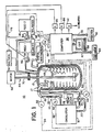
- Figure 1 depicts diagrammatically, the components of the presently preferred embodiment of this invention; and
- Figure 2 depicts diagrammatically, a sample plot of instantaneous heat flow rate values for an exemplary chemical reaction and for a subsequent calibration heat cycle of the calorimeter of Figure 1.
- Referring to the drawings, Figure 1 depicts diagrammatically a bench scale calorimeter according to a preferred embodiment of this invention and denoted generally by the
reference numeral 10, for determining the heat of reaction of and thermally controlling a chemically reacting mass. Thecalorimeter 10 includes aconventional reaction vessel 12, preferably a double glass walled, insulated container, for containing at least a liquid or solid chemically reacting mass. A fluid circulation system, denoted generally byreference numeral 14, contains a heat transfer fluid (not depicted). The preferred fluid is a silicone oil such as, for example, Rhone Poulenc 47-VR having a rated viscosity of 5 centistokes. Thesystem 14 includes a coil 16 for passing the fluid through thereaction vessel 12. In particular, the coil 16 is positioned within thereaction vessel 12 for intimate exchange of heat between the fluid in the circulation system and a chemically reacting mass contained within thereaction vessel 12. The coil 16 is made of a suitably non-reactive material such as 304 stainless steel. Preferably the coil 16 is removably attached to the remainder of thecirculation system 14 by conventional couplings 17 which permit the coil 16 to be removed for cleaning or replacement. Thefluid circulation system 14 further includes acirculator 18 which receives through anoutlet line 20, the fluid passing through the coil 16 and thereaction vessel 12. Thecirculator 18 returns that fluid to a predetermined temperature, which is preferably time constant but may vary according to a predetermined time schedule, for recirculating the heat transfer fluid through the coil 16 by an inlet line 22. To accomplish these circulating the temperature adjusting functions, thecirculator 18 includes a single, temperature-conditioning reservoir and receiving all the heat transfer liquid passing through the coil 16, a refrigeration/heating unit operating in the reservoir and a high efficiency pump. Thecirculator 18 may be, for example, a Lauda Circulator Model RCS 6 distributed in the United States by Brinkman Instruments. - The
calorimeter 10 further includes a fluid flow rate control subsystem, denoted generally byreference numeral 24. According to the invention, thesubsystem 24 is at least generally responsive to variations in temperature of the reacting mass within thereaction vessel 12 for varying flow rate of the fluid circulated through the reaction vessel portion of the circulation system. The preferred fluid flowrate control subsystem 24 is, in fact, almost instantaneously responsive to variations in temperature of the reacting mass contained in thereaction vessel 12. - To accomplish its purpose, the fluid flow
rate control subsystem 24 includes avalve 26, positioned in the inlet line 22 returning fluid to the coil 16, for varying rate of flow of the heat transfer fluid passing through the reaction vessel portion of the circulation system, i.e. the coil 16. The fluid flowrate control subsystem 24 further includes avalve actuator 28 coupled with thevalve 26 for varying the state ofvalve 26 and thereby varying flow rate of the heat transfer fluid through the coil 16. While any of a variety of valves might be employed, preferablyvalve 26 is one like a Badger Meter 3-way slide plate valve, for example, having a continuously varying setting for a continuous range of flow rates and three-way so as to proportion the fluid between the inlet line 22 carrying fluid to the coil 16 and aline 30 forming a loop by-passing the coil 16 and returning fluid to thecirculator 18. In this way, the load on the pump of thecirculator 18 can be held constant. Preferably theactuator 28 is a programmable device such as, for example, a Model 6000-T-MA-MA from Omega Engineering Company of Stamford, Connecticut, accepting at least one predetermined value representing a pre-set temperature and further responding to a control level voltage signal for providing a proportional response to the difference between the predetermined value and the signal. - Further according to the invention, to calculate the rate of heat transfer between the heat transfer fluid and the reacting mass there is provided a flow rate signal means 32 for generating a first signal related to varying flow rate of the fluid passing through the reaction vessel portion of the fluid circulation system. In the preferred embodiment, the flow rate signal means 32 is a signal generator that includes a flow rate sensing means 33 positioned along the outlet line 20 (or inlet line 22) of the
circulation system 14. A suitable flow rate signal generator with sensor is, for example, a Microflow Sensor (E range) with signal converter for 0-5 VDC output and, if desired, a DAD Flow Meter for visual output, all from Cole Parmer of Chicago, Illinois. The flow rate signal generated by thesignal generator 32 is carried online 34 to a suitable circuit which is responsive at least to that flow rate signal for generating a heat flow signal generally related to instantaneous rate of heat exchange between the reacting mass and the heat transfer fluid. In the preferred embodiment, such circuitry is provided by aprogrammable computer 36 such as an Apple Computer Model IIe. Associated with the computer are an operator display screen orCRT 38, a diskdrive storage device 40 and aprinter 42, each coupled with thecomputer 38 bylines - A first temperature signal means 44 for generating a first temperature signal related to the temperature of the reacting mass within the
vessel 12 is provided for controlling theactuator 28. Preferably, the first temperature signal means 44 includes asensor 45 positioned within thevessel 12 and suitably shielded to be inserted into a chemically reacting mass for sensing the actual temperature of the reacting mass to generate a first temperature signal passed alongline 46 to thevalve actuator 28 and along line 47 to thecomputer 38. A suitable first temperature sensing means 44 is, for example, a Model CPSS-116G-12-FEP, Teflon (Registered Trade Mark) coated thermocouple, from Omega Engineering, with associated circuitry for compensation and scaling of the thermocouple output to a 0-5 VDC signal range for use by thecontroller 28 and thecomputer 38. - Second and third
temperature signal generators thermocouple outlet lines 22 and 20, respectively, as well as associated circuitry for compensating and scaling the signal generated with eachthermocouple computer 38. The second and third temperature signals, so scaled, are carried to thecomputer 38 onlines computer 38 with the flow rate signal generated by the flowrate signal generator 32 to generate the heat flow signal. - An auxiliary heat source in the form of an electric heater 60 is provided extending into the interior of the
vessel 12 to calibrate theapparatus 10 for determining an absolute heat of reaction. The heater 60 is driven by a suitable electric power source, not depicted. The heater 60 is controlled by thecomputer 38 through arelay 62 switching the heater power supply on and off. A digital wattmeter 64 is also provided which measures the power being consumed by the heater 60, and outputs a measured wattage value to thecomputer 38 on line 65 for conversion into calories. A suitable heater 60 is, for example, a Glenn cartridge heater model S3-3210 while a suitable wattmeter is, for example, a Yew model 255510-4004. - The
apparatus 10 further includes an electronically controlledstirrer 66 including avariable speed motor 68,drive shaft 70 and removable prop 72, which may be flat or pitched. Rotational speed of thestirrer 66 is measured by suitable, conventional means such as adigital tachometer 74. The tachometer signal is passed to thecomputer 38 online 76. - The
preferred embodiment calorimeter 10 further includes a reagent dosing subsystem which includes a plurality ofreservoirs 78 and 80, the contents of which are fed into thereaction vessel 12 by means of electronically controlled metering pumps 82 and 84 respectively. Thepumps 82 and 84 are controlled through thecomputer 38 by means ofrelays reservoirs 78 and 80 is determined by positioning the reservoirs onelectronic balances balances computer 34 bylines - Heat flow rate between the reacting mass and heat transfer fluid is determined by the formula:
qr = F (To - Ti) K (1)
where qr = heat flow rate between transfer fluid and reacting mass;
F = heat transfer fluid flow rate;
To = temperature of heat transfer fluid exiting the coil;
Ti = temperature of heat transfer fluid entering the coil; and
K = calibration factor. - The calibration factor K is related to the specific heat of the heat transfer fluid and is determined by activating the heater 60 immersed in the reaction mass. The energy evolved from the heater 60 is measured by the digital wattmeter 64, the output of which is relayed to the
computer 38 on line 65. The response of the system to this measured heat load yields the calibration factor K. The preferred embodiment calorimeter has been designed to measure and store values from each temperature signal and the flow rate signal at the rate of 30 data points per minute by means of a multiplexer and analog to digital converter such as, for example, the Adalab add-on package with AI13 high speed option and multiplexer from Interactive Microware, State College, Pa., receiving these various signals at thecomputer 38. These measured values are stored, together with the instantaneous heat flow signal values generated according to formula (1), for subsequent retrieval to calibrate the instantaneous heat flow data and calculate total heat of reaction. - During the course of an experiment, all computer inputs and the estimated heat flow values are passed by signal on
line 39 tooperator display screen 38. The values are periodically refreshed such as at two seconds intervals. After each reaction run, the data collected are processed and may be stored on the storage medium of thedisk drive 40 and printed through theprinter 42, if hard copy is desired. - Fig. 2 illustrates the results of an isothermal batch reaction of an exothermic nature. Instantaneous heat flow values 100, calculated every two seconds according to the formula (1) are recorded. The time varying mean of th data values 100 is represented by a
solid curve 102. Also included is acalibration curve 104. - The
curve 104 was generated subsequent to the chemical reaction fromdata 100 derived by operation of the heater 60. Calibration after reaction enables the use of the entire reacted mass as the calibration sample. Thus, the system is configured in essentially the same way (i.e. essentially the same total volume) in which it was configured during the reaction. Alternatively, one or more components, which are not spontaneously reactive, can be fed into the reaction vessel and used as the calibration sample if a calibration run is desired before the reaction. However, typically in such cases, the volume of the calibration sample will be less than that of the reacting mass. - Integration of the
calibration curve 104 will yield the calibration factor K. Factor K equals the measured heat (wattmeter measurement) divided by the integral of thecalibration curve 104. The factor K can then be applied to the integral of thereaction curve 102 to determine the absolute heat of reaction. - The system is normally operated to maintain the reaction mass at a constant temperature determined by the set point of the
valve actuator 28, which functions as the temperature controller. Any deviation from the set point caused by heat liberated or absorbed by the reacting mass is relayed to theactuator 28 through thefirst temperature thermocouple 45 causing theactuator 28 to adjust the setting three-way control valve 26 to permit the proper amount of heat transfer fluid to be sent to the coil 16 to control the temperature of the reacting mass. - For bench scale operation, the reaction vessel is conveniently sized at about five liters or less in capacity, suggestibly about two liters in capacity for convenience. A two-liter capacity enables a
single circulator 18 of the type previously identified to be employed providing a temperature operating range of -30 degrees to 120 degrees Centigrade. Theaforesaid circulator 18 has a capacity of approximately 6 liters and is able to circulate the heat transfer fluid at a maximum rate of about 2 liters per minute. - It has been found that reactions in a two-liter capacity vessel are easily controlled with about 100 square inches (about 645 square centimeters) of coil surface area. To provide such a surface area, the tubing of the coil 16 can be, for example, about 0.375 inches (9.5 mm) in outer diameter, coiled in loops about 3.75 inches (95 mm) in outer diameter, one loop contacting the next, to a height of about 3.5 inches (about 90 mm). A coil with an equivalent number of loops, spaced slightly apart from one another to provide a greater coil height, such as about 4.25 inches (about 110 mm), might alternatively be employed for ease of coil cleaning. It is believed that reaction control can be effectively maintained and heat of reaction still accurately measured with a coil surface area to reaction vessel capacity ratio as little as one-half the ratio indicated above, i.e. with a ratio as low as about 25 square inches (about 160 square centimeters) of coil surface area per liter of reaction vessel capacity.
- Preferably, the set point temperature of the
actuator 28 and the temperature of the reservoir of thecirculator 18 are selected to yield a flow rate of the heat transfer fluid so as to maintain a discernible difference between fluid inlet and outlet temperatures. In particular, a temperature difference of at least six degrees Centigrade or more between the heat transfer fluid entering and exiting the coil 16 is preferred to minimize systematic errors occurring in the normal operation of thethermocouples - The
computer 38 can be used to control the feeding of predetermined quantities of each reagent into thevessel 12 by suitable cycling of the solid state relays 86 and 88. As a precaution against runaway reactions, any potentially dangerous temperature deviation of the reaction mass can be used to cause the feed pump relays 86, 88 and theheater relay 62 to be cycled so as to terminate reagent feed and/or heating until the reaction is once again under control. Conveniently, this function can be provided by programming the computer to compare the difference between the reaction temperature and a predetermined temperature or schedule of time varying temperatures against some maximum temperature difference value (or to compare the reaction temperature to an absolute maximum or minimum temperature) and responding if the maximum temperature difference (or the pertinent maximum or minimum temperature) is exceeded. - While a preferred embodiment of the invention has been disclosed, variations will occur to those of ordinary skill in the art. For example, alternatively and less desirably, a signal indicating flow rate may be generated indirectly by calibration of the reaction temperature output signal or a signal generated by the
actuator 28 to actual fluid flow rate and used. Also, rather than actually measuring the temperature of the heat transfer fluid being passed into the coil 16, a predetermined value may be entered into the computer's storage, corresponding either to the temperature value preset into thecirculator 18 or a measured value of fluid temperature at the reaction vessel corresponding to that set point temperature of the circulator. That value, rather than actual measured input temperature, could also be used to calculate heat transfer rate. - Alternatively, and also less desirably in terms of response time, the
actuator 28 may be controlled by the fluid outlet temperature signal. It may even be controlled in some instances by a signal generator predicting a generally known temperature profile for a reaction. - In addition, while a programmable computer is preferred, generation of the instantaneous heat transfer rate signal and determination of the heat of reaction can alternatively be accomplished by firmware or by hard-wired digital and/or analog circuitry.
- From the foregoing description, it can be seen that the present invention provides a self-contained, automatic calorimeter with a variable flow rate, heat transfer fluid circulation system for accurate heat transfer measurement and rapid reaction response. In particular, the
device 10 has proved invaluable in the control of peroxidation reactions. These reactions evolve a sharp initial charge of heat energy which can result in reaction runaway if not carefully controlled. Also, the accurate, rapid control of heat provided by the subject system is important in achieving uniform yield and product quality. - It will be recognized by those skilled in the art that changes in addition to those already mentioned could be made to the above-described embodiment in the invention, without departing from the broad inventive concepts thereof. It is understood, therefore, that this invention is not limited to the particular embodiment and variations thereto disclosed, but is intended to cover any modification which is within the scope and spirit of the invention, as described herein.
Claims (16)
Applications Claiming Priority (2)
| Application Number | Priority Date | Filing Date | Title |
|---|---|---|---|
| US134392 | 1987-12-17 | ||
| US07/134,392 US4846584A (en) | 1987-12-17 | 1987-12-17 | Automated calorimeter and methods of operating the same |
Publications (2)
| Publication Number | Publication Date |
|---|---|
| EP0321210A2 true EP0321210A2 (en) | 1989-06-21 |
| EP0321210A3 EP0321210A3 (en) | 1991-01-16 |
Family
ID=22463166
Family Applications (1)
| Application Number | Title | Priority Date | Filing Date |
|---|---|---|---|
| EP19880311827 Withdrawn EP0321210A3 (en) | 1987-12-17 | 1988-12-14 | Automated calorimeter and methods of operating the same |
Country Status (4)
| Country | Link |
|---|---|
| US (1) | US4846584A (en) |
| EP (1) | EP0321210A3 (en) |
| JP (1) | JPH01197643A (en) |
| CA (1) | CA1315567C (en) |
Cited By (1)
| Publication number | Priority date | Publication date | Assignee | Title |
|---|---|---|---|---|
| ES2162766A1 (en) * | 2000-06-15 | 2002-01-01 | Consejo Superior Investigacion | Combustion microcalorimeter. |
Families Citing this family (16)
| Publication number | Priority date | Publication date | Assignee | Title |
|---|---|---|---|---|
| US6435710B1 (en) | 1998-08-26 | 2002-08-20 | Fauske & Associates, Inc. | Foam detector apparatus and method |
| US6157009A (en) * | 1998-08-26 | 2000-12-05 | Fauske And Associates, Inc. | Advanced reactive system screening tool |
| US6908686B2 (en) | 2002-11-26 | 2005-06-21 | Dupont Teijin Films U.S. Limited Partnership | PEN-PET-PEN polymeric film |
| US7488106B2 (en) * | 2005-05-05 | 2009-02-10 | Leco Corporation | Automated calorimeter |
| US7481575B2 (en) * | 2005-05-05 | 2009-01-27 | Leco Corporation | Calorimeter |
| CN100429493C (en) * | 2005-05-25 | 2008-10-29 | 中国石油天然气股份有限公司 | Method and device for measuring heat of chemical reaction |
| KR100776914B1 (en) * | 2005-06-14 | 2007-11-15 | 주식회사 엘지화학 | Temperature measuring device |
| WO2007029218A1 (en) * | 2005-09-09 | 2007-03-15 | Pfizer Science And Technology Ireland Limited | Apparatus for low temperature reaction process |
| FR2923010B1 (en) * | 2007-10-26 | 2012-05-18 | Commissariat Energie Atomique | DEVICE AND METHOD FOR MEASURING THE RESIDUAL POWER OF A LOAD |
| EP2133676B1 (en) * | 2008-06-13 | 2013-03-13 | Mettler-Toledo AG | Calorimetric method |
| EP2560759B1 (en) * | 2010-04-20 | 2020-02-12 | QIAGEN GmbH | Temperature control method and apparatus |
| CN102230907B (en) * | 2011-03-29 | 2014-06-18 | 长沙开元仪器股份有限公司 | Calorimeter |
| US9140504B1 (en) * | 2012-02-02 | 2015-09-22 | The United States Of America As Represented By The Secretary Of The Army | Performance testing apparatus for microclimate cooling unit |
| JP6257636B2 (en) * | 2012-11-27 | 2018-01-10 | ラミナー カンパニー,リミテッド | Reactor for mixing and production method using the reactor |
| CN103196945B (en) * | 2013-03-18 | 2014-12-17 | 哈尔滨工程大学 | A condensation heat transfer experimental device that can realize the coupling of natural circulation and forced circulation |
| CN113467540B (en) * | 2021-06-16 | 2022-03-08 | 安徽翔弘仪器科技有限公司 | Intelligent high-low temperature intelligent control system for medicine processing |
Family Cites Families (9)
| Publication number | Priority date | Publication date | Assignee | Title |
|---|---|---|---|---|
| US2163730A (en) * | 1935-03-29 | 1939-06-27 | Goetzl Manlio | Integrating calorimeter |
| US2974017A (en) * | 1957-11-21 | 1961-03-07 | Phillips Petroleum Co | Measurement of polymerization reractions |
| CH455325A (en) * | 1966-04-18 | 1968-06-28 | Ciba Geigy | Device for measuring the heat generation rates of chemical reactions |
| DE2008690C3 (en) * | 1969-02-26 | 1975-05-22 | Tokico Ltd., Kawasaki, Kanagawa (Japan) | Heat meter |
| US3967492A (en) * | 1972-05-09 | 1976-07-06 | Instrumentation Specialties Company | Heat of interaction detector |
| SE377348B (en) * | 1972-07-14 | 1975-06-30 | Mo Och Domsjoe Ab | |
| US3994164A (en) * | 1973-06-25 | 1976-11-30 | Ciba-Geigy Corporation | Apparatus for the determination of the thermal efficiency of chemical reactions |
| CH571218A5 (en) * | 1973-10-26 | 1975-12-31 | Sandoz Ag | Heat of reaction measurement - using rotating flow of heating or cooling fluids for reaction vessel |
| CH651392A5 (en) * | 1980-06-10 | 1985-09-13 | Ciba Geigy Ag | HEAT FLOW CALORIMETER. |
-
1987
- 1987-12-17 US US07/134,392 patent/US4846584A/en not_active Expired - Fee Related
-
1988
- 1988-11-28 CA CA000584348A patent/CA1315567C/en not_active Expired - Fee Related
- 1988-12-13 JP JP63313078A patent/JPH01197643A/en active Pending
- 1988-12-14 EP EP19880311827 patent/EP0321210A3/en not_active Withdrawn
Cited By (1)
| Publication number | Priority date | Publication date | Assignee | Title |
|---|---|---|---|---|
| ES2162766A1 (en) * | 2000-06-15 | 2002-01-01 | Consejo Superior Investigacion | Combustion microcalorimeter. |
Also Published As
| Publication number | Publication date |
|---|---|
| JPH01197643A (en) | 1989-08-09 |
| CA1315567C (en) | 1993-04-06 |
| EP0321210A3 (en) | 1991-01-16 |
| US4846584A (en) | 1989-07-11 |
Similar Documents
| Publication | Publication Date | Title |
|---|---|---|
| US4846584A (en) | Automated calorimeter and methods of operating the same | |
| US4963499A (en) | Method for the calorimetry of chemical processes | |
| US4892707A (en) | Apparatus for the calorimetry of chemical processes | |
| Christensen et al. | Isothermal high pressure flow calorimeter | |
| EP2052242B1 (en) | Determination of the specific heat capacity | |
| US4130016A (en) | Adiabatic calorimeter apparatus and method for measuring the energy change in a chemical reaction | |
| JP3546194B2 (en) | Parallel processing device for reaction mixture | |
| US3994164A (en) | Apparatus for the determination of the thermal efficiency of chemical reactions | |
| US4923306A (en) | Stable isothermal calorimeter | |
| US7476020B2 (en) | Method for simulating a process plant at laboratory scale | |
| JP4446884B2 (en) | Method for using a heat flux sensor to evaluate the strength of a thermal reaction in a container and apparatus for performing the method | |
| Christensen et al. | Isothermal, isobaric, elevated temperature, high‐pressure, flow calorimeter | |
| JP2009300443A (en) | Method for operating calorimeter | |
| JP4807922B2 (en) | Calorimeter | |
| US5322360A (en) | Isothermal calorimeter | |
| US4088447A (en) | Adiabatic calorimeter apparatus and method for measuring the energy change in a chemical reaction | |
| Hansen et al. | The art of calorimetry | |
| US5174655A (en) | Calorimeter sensor | |
| Stoessel | Applications of reaction calorimetry in chemical engineering | |
| US3951386A (en) | Uniform mixing in vessels | |
| US3869914A (en) | Isothermal calorimetry method and apparatus therefor | |
| EP0170713B1 (en) | Method and apparatus for the calorimetry of chemical processes | |
| EP0275042A2 (en) | Apparatus for measuring exothermic reaction energy release | |
| Hansen et al. | Recent advances in titration calorimetry | |
| Wright et al. | Adiabatic dewar calorimeter |
Legal Events
| Date | Code | Title | Description |
|---|---|---|---|
| PUAI | Public reference made under article 153(3) epc to a published international application that has entered the european phase |
Free format text: ORIGINAL CODE: 0009012 |
|
| AK | Designated contracting states |
Kind code of ref document: A2 Designated state(s): BE CH DE FR GB IT LI NL |
|
| RAP1 | Party data changed (applicant data changed or rights of an application transferred) |
Owner name: ATOCHEM NORTH AMERICA, INC. |
|
| PUAL | Search report despatched |
Free format text: ORIGINAL CODE: 0009013 |
|
| AK | Designated contracting states |
Kind code of ref document: A3 Designated state(s): BE CH DE FR GB IT LI NL |
|
| 17P | Request for examination filed |
Effective date: 19910615 |
|
| 17Q | First examination report despatched |
Effective date: 19930127 |
|
| STAA | Information on the status of an ep patent application or granted ep patent |
Free format text: STATUS: THE APPLICATION IS DEEMED TO BE WITHDRAWN |
|
| 18D | Application deemed to be withdrawn |
Effective date: 19930831 |