EP0321200A2 - Rotary facial seal and bearing assembly - Google Patents
Rotary facial seal and bearing assembly Download PDFInfo
- Publication number
- EP0321200A2 EP0321200A2 EP88311814A EP88311814A EP0321200A2 EP 0321200 A2 EP0321200 A2 EP 0321200A2 EP 88311814 A EP88311814 A EP 88311814A EP 88311814 A EP88311814 A EP 88311814A EP 0321200 A2 EP0321200 A2 EP 0321200A2
- Authority
- EP
- European Patent Office
- Prior art keywords
- seal
- shaft
- assembly according
- housing
- wall
- Prior art date
- Legal status (The legal status is an assumption and is not a legal conclusion. Google has not performed a legal analysis and makes no representation as to the accuracy of the status listed.)
- Granted
Links
Images

Classifications
-
- F—MECHANICAL ENGINEERING; LIGHTING; HEATING; WEAPONS; BLASTING
- F16—ENGINEERING ELEMENTS AND UNITS; GENERAL MEASURES FOR PRODUCING AND MAINTAINING EFFECTIVE FUNCTIONING OF MACHINES OR INSTALLATIONS; THERMAL INSULATION IN GENERAL
- F16J—PISTONS; CYLINDERS; SEALINGS
- F16J15/00—Sealings
- F16J15/16—Sealings between relatively-moving surfaces
- F16J15/34—Sealings between relatively-moving surfaces with slip-ring pressed against a more or less radial face on one member
- F16J15/3436—Pressing means
- F16J15/3456—Pressing means without external means for pressing the ring against the face, e.g. slip-ring with a resilient lip
-
- F—MECHANICAL ENGINEERING; LIGHTING; HEATING; WEAPONS; BLASTING
- F16—ENGINEERING ELEMENTS AND UNITS; GENERAL MEASURES FOR PRODUCING AND MAINTAINING EFFECTIVE FUNCTIONING OF MACHINES OR INSTALLATIONS; THERMAL INSULATION IN GENERAL
- F16J—PISTONS; CYLINDERS; SEALINGS
- F16J15/00—Sealings
- F16J15/16—Sealings between relatively-moving surfaces
- F16J15/32—Sealings between relatively-moving surfaces with elastic sealings, e.g. O-rings
- F16J15/3204—Sealings between relatively-moving surfaces with elastic sealings, e.g. O-rings with at least one lip
Definitions
- This invention relates to seals; and more particularly relates to a novel and improved grease or oil facial seal used alone or in combination with a bearing assembly disposed between two relatively movable or relatively rotatable parts, such as, a stationary housing and a rotatable and axially movable shaft.
- Diaphragm-type seals have been employed in the past in rotary seal applications, such as, between a rotating axle and a spindle housing in a motor vehicle.
- the seal ring be so constructed and arranged as to establish a thin annular band of contact at its sealing surface with a surface to be sealed.
- This thin band of contact results in optimum sealing conditions and prevents contamination as well as excessive wear of the seal face otherwise occasioned when the axially directed force is spread over a more limited surface area on the seal face.
- the thin band of contact also has been found to establish improved sealing notwithstanding imperfections in the surface to be sealed and high rates of shaft rotation resulting in application of centrifugal forces which are exerted outwardly upon the seal ring and face.
- seal face be axially loaded or biased in such a way as to remain in contact with the surface to be sealed irrespective of forces exerted upon the seal face and changes in atmospheric pressure or other pressure changes which may occur as a result of translational shaft movement or sudden changes in temperature.
- the seal is a facial seal adaptable for use between a spindle housing and axle in automotive applications.
- Features of the invention may be employed, too, in other applications and environments.
- a preferred form of rotary facial seal is adapted to be disposed between an outer member, such as, for example, a stationary spindle housing and an inner member, such as, for example, an axle.
- the axle shaft is rotatably and axially movable with respect to the spindle housing and there is a radial wall on the housing.
- the seal assembly includes an annular diaphragm of elastomeric material having an inner seating portion disposed around the axle and an outer sealing lip tapering in an axial direction away from the outer periphery of the diaphragm into sealing contact with the radial wall of the housing; and the diaphragm having a toroidal-shaped intermediate wall to yieldingly urge the sealing lip into a thin annular band of contact with the radial wall of the housing whereby the sealing lip is self-compensating for wear and prevents entry of contaminants into the space between the spindle housing and axle.
- the diaphragm including the seal ring and lip are preferably of unitary construction, and an outer seal body of the diaphragm joining the toroidal wall section to the seal lip is selectively reduced in cross-section to define a circumferential hinge which encourages the seal lip to flare outwardly under the biasing action of the intermediate wall section.
- the thin band of contact established by the seal lip with the radial wall enables applied forces to be distributed over a broader surface area than a line of contact thereby permitting faster running with less heat build-up that otherwise may tend to cause increased friction and wear as well as a tendency of the lip to stick to the radial wall surface.
- Rigid reinforcing rings are preferably incorporated into the inner seal ring and outer seal body, the outer ring acting as a directional fulcrum through which the force imparted by the rolling action of the wall section is directed toward the face of the seal lip.
- the axle shaft is rotatable about a linear axis while the spindle housing remains relatively fixed; alternatively, the shaft may be fixed while the housing is rotated.
- the seal preferably is mounted on or with respect to the shaft in generally concentric relation to the shaft and axis thereof, and the thin annular band of contact the sealing lip makes with the radial wall of the spindle housing preferably also is generally concentric with respect to the axle shaft and axis thereof.
- the spindle housing also may include a portion which is generally concentric with the shaft.
- the radial wall against which the sealing lip may bear to form the thin annular band of contact may be referred to as an axial face or as a counterface.
- a seal according to one preferred embodiment of the present invention for plural members which are relatively movable, for example, relatively rotatable or axially movable, members includes a first body or seating portion, a sealing portion, and an intermediate portion.
- the first body portion positions the seal in place with respect to one of the plural members, such as an axle shaft.
- first body portion may be referred to as a seal ring or as an inner seal ring, e.g., due to relative location thereof in the preferred embodiment of the invention.
- the sealing portion provides the sealing function with respect to a second member, such as the axial face or counterface of a spindle housing.
- such sealing portion may be referred to as a sealing lip.
- the intermediate portion which sometimes is referred to as a toroidal-shaped wall section or toroid of a diaphragm member, couples the body portion and the sealing portion and in a sense energizes the seal to provide a sealing force that preferably accommodates axial and radial relative movement of the first and second members.
- the sealing lip is located radially outward relative to the first body portion. If desired, the positional relationship of those portions and of other portions of the seal of the invention may be varied within the spirit and scope of the invention. Also, preferably a body, referred to below as an outer seal body due to relative location in the preferred embodiment, joins the toroidal-shaped wall section to the sealing lip and in a sense provides support for the sealing lip.
- a mechanism is provided to enable a hinge-like action that facilitates an outward bending or flaring of the sealing lip relative to the outer seal body in response to a biasing force or action of the toroidal-shaped wall that urges the sealing lip toward the axial face of the spindle housing; and that mechanism is a reduced cross-section portion of the outer seal body which defines a hinge, preferably a circumferential hinge.
- the outer seal body is of a substantially uniform cross-section and is free to hinge or flex more about the toroidal shaped wall section than in the one embodiment so that the seal body can redirect its force along the radial wall of the spindle housing more in a radial outward direction and with minimal loading imposed on the surface area engaged by the seal.
- the sealing lip Under the influence of the toroidal-shaped wall and outer seal body, the sealing lip forms a thin annular band of contact with the radial wall of the spindle housing, for example.
- Such thin annular band of contact rather than a line of contact, enables applied forces to be distributed over a relatively broad surface area than would be the case for a line of contact; and this distrubtion permits faster running of the seal and apparatus on which it is used with less frictional heat build-up that otherwise may tend to cause increased friction and wear.
- the seal may include one or more relatively rigid members that tend to reinforce various portions of the seal or assist in maintaining radial and axial stability of the seal. Those members may be separate from or part of one or more of the other portions of the seal and may be of metal, plastic, or other relatively rigid material. Moreover, in the preferred embodiments, one of such relatively rigid members is attached to or is incorporated into the inner seal ring to facilitate secure mounting of the seal on an axle shaft, for example; and in one of the embodiments a second relatively rigid member is attached to or is incorporated into the outer seal body to act as a directional fulcrum or leverage point through which force imparted by a rolling action of the toroidal-shaped wall is directed toward the sealing lip to seal against the axial face of the spindle housing.
- a thrust bearing may be installed at the inner face of the radial wall and inner bore of the spindle housing with a seal element surrounding the axle, the bearing being freely rotatable with respect to the spindle housing and seal element.
- seal assembly 8 broadly comprised of a rotary facial seal 10 and a thrust bearing unit 12 interposed between two inner and outer spaced, relatively moving members, 14,16.
- the seal assembly 8 is shown installed between an outer stationary spindle housing 14 and an inner drive shaft or axle 16 of a motor vehicle.
- the axle 16 terminates at its outboard end in a radial surface portion 17, axially directed shoulder 18 and enlarged end 20.
- the spindle housing 14 has an inner bore 22 in outer spaced facing relation to the shaft 16, a radially extending wall surface 24, also referred to as an axial face or counterface, in facing relation to the radial wall 17 of the shaft 16 and a circular flange 26 projecting outwardly from the outboard end of the housing 14.
- the shaft 16 has a linear axis about which it may rotate, and the spindle housing bore 22 is located about part of the shaft such that the bore and shaft are concentric or substantially concentric. In a sense, then, the spindle housing 14 may be at least partly concentric with the shaft. Precise concentricity is not necessarily a restriction for proper use and operation of the invention; indeed concentricity ordinarily would not be required for use and operation of the invention.
- the facial seal 10 is so mounted between the spindle housing 14 and shaft 16 as to prevent ingress of dust, water or other contaminants into the space or area between the housing 14 and shaft 16 and at the same time to prevent the migration of lubricant, such as grease, out of that area.
- the facial seal 10 is capable of compensating for liberal end-play and shaft misalignment as well as a lesser degree of axial biasing when the shaft is either rotating or not rotating in relation to the housing 14.
- the facial seal 10 has been found to be effective under negative pressure to hold relatively securely against the axial face or counterface 24 thereby maintaining the integrity of the seal.
- the seal 10 comprising a diaphragm 30 of elastomeric or rubber or rubber-like material having an inner seating portion 32, a generally toroidal shaped wall section 33 and outer concentric seal body 34.
- the inner concentric seating portion 32 is affixed to a ring member 36, which is relatively more rigid than the diaphragm so that when the seal 10 is installed onto the shaft 16 as shown in Figures 1 and 2 in a manner to be described, the seating portion 32 is compressed between the rigid ring 36 and the shaft 16.
- An outer backing ring member 38 also is a rigid member which is permanently affixed to the seal body 34 in outer spaced concentric relation to the inner seating portion 32 and functions to maintain the integrity of the seal body, and acts as a directional fulcrum through which the force imparted from translational or rolling movement of the wall 33 is applied via seal body 34 to a tapered seal lip 40 at the end of the seal body 34 which is in facing relation to the spindle housing 14 as shown in Figures 1 and 2.
- the toroidal wall section 33 is capable of axially loading or biasing the seal lip 40 against the spindle housing 14 when axial or translational movement occurs between the shaft 16 and housing 14 without the aid of separate biasing or spring elements.
- the necessary resilience is incorporated into the toroidal shaped, flexible wall 33 of the diaphragm so as to act very much in the manner of a cantilever in yieldingly urging the seal lip 40 into constant engagement with the radial wall of the spindle housing 14 notwithstanding axial movement between the shaft 16 and housing 14.
- the free, or relaxed, state of the wall section 33 is shown in Figure 5; i.e., the wall section 33 is molded into a configuration such that, as it advances toward the relationship shown in Figure 3, it will store an increasing biasing force tending to return it to the position shown in Figure 5.
- the seating portion 32 defines one side or leg of a generally U-shaped inner terminal end section 42 of the diaphragm 30, the opposite side or leg 44 defining an axially directed, outboard continuation of the toroidal shaped wall section 33, and a closed end 46 of the section 42 joining the seating portion 32 and leg 44.
- the rigid ring 36 is of generally L-shaped cross-section and is preferably composed of a rigid metal material including an axially extending flange 46 inserted through the open end of the U-shaped section 42 and a radially inwardly directed flange 47 at one end of the flange 46.
- the ring 36 is mechanically held in place and united with the seating portion 32 by forming a series of holes or bores 48 through which the elastomeric material of the diaphragm 30 flows during the molding process of the diaphragm.
- Mechanical bonding in the manner described avoids necessity of chemical bonding and enables the ring 36 to be united with the inner seating portion 32 and inner leg 44 during the molding or curing process.
- the wall section 33 will undergo a rolling action as it flexes in response to relative movement between the outer and inner concentric members 14 and 16, respectively.
- the wall section 33 is of generally toroidal or concavo-convex configuration with its convex wall surface in facing relation to the outer member 14.
- the wall section is of uniform thickness in extending from the inner leg 44 across the generally circular or arcuate wail proper, as designated at 33, into an axially extending, outer concentric end or leg 52.
- the outer end 52 of the wall 33 is integrally united to the outboard end of the seal body 34 and is free to roll along inner surface 56 of the seal body in response to translational or axial movement of the shaft 16 as described.
- the diaphragm 30 is molded so that in its relaxed state it is in the inboard extended position shown in Figure 5.
- the outer peripheral end or leg 52 of the wall section 33 is joined to the seal body at an angle such that movement of the inner seating portion 32 in an axial direction toward the radial wall, as noted in the succession of movement illustrated in Figures 4 and 3 will cause the outer end 52 to roll outwardly along the inner circumferential surface of the seal body.
- the outer end 52 will continue to yieldingly urge the seal lip 40 against the radial wall.
- This biasing force exerted by the outer end 52 is assisted by the resiliency or biasing action of the entire wall section 33 and inner leg or end 44.
- the seal body 34 preferably is in the form of a solid, generally rectangular solid block of a greater radial thickness than the remainder of the body to be described so as to be relatively inflexible with respect to the sealing lip 40.
- the backing ring 38 is of generally L-shaped cross-section and is molded into the body 34 with axially directed flange 61 molded into an outer circumferential surface 62 of the block and flange 63 molded into radially directed outboard end surface 64 of the block.
- the backing ring 38 is a rigid member to maintain the integrity or uniformity of the diameter of the seal body and to act as a directional fulcrum through which the force imparted from rolling of the wall section 33 is directed into the face of the seal lip 40.
- the seal body 34 converges at the end opposite to the backing ring 38 into a hinged section 66 and thereafter continues into tapered section 68 which terminates in the sealing lip 40.
- the hinged section 66 is defined by inclined surfaces 70 and 72 intersecting along a common circumferential line of intersection 73. Hinging occurs at the intersection 73 of the surfaces 70 and 72 by reducing the cross-sectional thickness of the section behind the hinge, preferably by forming an outside circumferential groove or radius 74 which is offset slightly outboard of the hinge line 73.
- An outer circumferential surface 76 inclines radially and outwardly to intersect with a radially outwardly directed surface 77 and converge at the sealing lip 40 as illustrated.
- the combination of the location of the hinge line 73 and groove 74 permits radially outward flaring of the seal lip 40 about the hinge 73 when the lip 40 bears against the sealing interface defined by the radial wall 24 of the spindle housing.
- This outward hinging or flaring also acts as a secondary means of loading the seal lip 40 axially in the same fashion as a spring would act to direct force in a linear or axial direction.
- the surface 77 adjacent to the sealing lip 40 is inclined at a steep radial angle so as to define a thin band of sealing contact when flared outwardly as described and enables the sealing force to be spread over a broad surface area on the radial wall 24 of the housing 14.
- the seal lip By spreading the force over a broader surface area, the seal lip is capable of running at high speeds with minimal heat build-up and wear on the surface 77, and the axial biasing action of the diaphragm enhances sealing contact along the entire circumferential surface of the sealing lip with the radial wall surface 24. Any increased biasing force or pressure exerted upon the seal lip, as the inner seating portion 32 is axially advanced toward the radial wall is accommodated by the outward flaring or hinging action of the seal lip about the hinge line 73.
- a preferred form of thrust bearing 12 is of generally annular configuration and is mounted at the inner bore of the spindle housing in sealed relation to the shaft 16 and in journaled relation to the housing 14.
- the thrust bearing 12 comprises a seal retainer ring 80 having a radially inwardly directed end flange 81 and a radially outwardly directed end flange 82 at the opposite end of the ring 80.
- An annular seal 83 includes a seal lip 84 at its inner radial end and an endless coiled spring member 85 in outer surrounding relation to the seal which acts to compress the seal in an inward radial direction against the surface of the shaft 16.
- a bearing member 86 is composed of a hard, rugged plastic material, such as, an internally lubricated Nylon composition characterized by having a low dynamic coefficieint of friction.
- the bearing member 86 is given a cross-sectional configuration complementary to that of the ring 47 and wall 17 so that when the end of the shaft 16 moves against the bearing member 86, it will bear against the outboard surfaces 87 and 88 as well as to force the member 86 against the radial wall 24 of the housing 14, and prevent direct frictional contact between the shaft 16 and the spindle housing 14.
- the bearing member 86 includes an outboard surface having a radially extending portion 87 and shoulder portion 88 with a stepped surfact 89 therebetween and an inner radial end 90 which is chamfered so as to act as a guide in centering the shaft 16 when the shaft is installed within the bearing 12.
- Inboard surface 94 of the bearing member 86 is provided with a circular groove 92 having a slight overhang 93 for snapfit insertion of the outwardly directed flange 88 on the ring 80 so that the bearing member 86 is journaled on the ring 80 and is free to spin or rotate with respect to the rest of the bearing assembly. While acting as a bearing, it is beneficial for the bearing member 86 to be able to spin freely in relation to the seal portion of the assembly, which is mounted in fixed relation to the spindle housing, so that the force of friction exerted by the end of the shaft will be applied directly to the bearing surfaces 87 and 88 as well as to inboard surface 94. Being free to rotate with respect to the spindle housing, the bearing member 86 will therefore rotate with, but at a lesser speed than, the rotational speed of the shaft.
- the thrust bearing assembly 12 as described is advanced into pressfit engagement within the bore 22 of the spindle housing, preferably with the assistance of a flat tool which is pressed against the outboard surface of the bearing member 86 to force the retainer ring 80 uniformly into snug-fitting engagement with the surface of the inner bore.
- the bearing 12 can be installed without direct engagement with the seal 83.
- the bearing member 86 effectively encloses or protects the spring member 85 backing the seal 83 and protects it from displacement during installation into the bore.
- a modified form of seal assembly 8′ comprises a rotary facial seal 100 and a thurst bearing unit 12′ interposed between the members 14′ and 16′, the member 14′ again designating an outer stationary spindle housing and member 16′ designating an inner drive shaft having a radial surface 17′, shoulder 18′ and enlarged end 20′.
- Housing member 14′ has an inner bore 22′, radial wall surface 24′ and circular flange 26′.
- the facial seal 100 again comprises a diaphragm 102 of elastomeric material having an inner seating portion 32′, a generally toroidal shaped wall section 33′ and an outer seal body 104.
- the seating portion 32′ is affixed to a ring member 36′ in a manner corresponding to that of the form of seal 10 shown in Figures 1 and 2, and the toroidal-shaped wall section 33′ is constructed and arranged in a manner corresponding to that of the wall section 33 of the seal 10 for the purpose of yieldingly urging the outer seal body 104 into constant engagement with the radial wall 24′ of the housing 14′ notwithstanding axial displacement of the housing 14′ and the shaft 16′.
- FIG. 10 to 12 An important feature of the form of invention shown in Figures 10 to 12 is the modified construction of the outer seal body 104 so as to be of substantially uniform cross-sectional thickness throughout, except for a tapered surface portion 106 which terminates in a seal lip 108 at the free end of the seal body 104 opposite to connecting end 110. As shown, the surface portion 106 inclines at a low gradual angle away from the inner circumferential wall surface of the seal body until it intersects with the outer circumferential wall surface.
- the connecting end 110 is integrally formed with the outer end or leg 52′ of the toroidal wall section 33′, and the thickness at the connecting end 110 is increased by that of the leg 52′, and is greater than that of the toroidal wall section 33′ so as to be relatively inflexible with respect to the toroidal section 33′.
- the seal body as described has sufficient integrity at its connection to the toroidal wall section 33′ so as to act as a directional fulcrum through which the force imparted by the rolling action of the wall section 33′ can be directed into the face of the seal lip 108 without requiring a backing ring, such as, the backing ring 38 as shown in Figures 1 to 8.
- the entire diaphragm 102 is molded so that in its relaxed state it will assume the inboard extended position shown in Figure 11 with the seal body 104 diverging slightly in an outward radial direction from the connecting end 104 to the opposite free end portion 106. Movement of the inner seating portion 32′ axially towards the radial wall 24′, as noted in Figure l2, will cause the wall section 33′ to roll in an outboard direction away from the face or wall 24′ along the inner circumferential surface 112 of the seal body 104. Conversely as the inner seating portion 32 is moved axially away from the wall 24′ toward the position shown in Figure 1, the wall section 33′ and its outer end 52′ will continue to yieldingly urge the seal lip 108 against the wall 24′.
- rotary facial seal assemblies 10 and 100 are such that no special tooling is required for the installation of either assembly onto the shaft 16 or 16′; nor are special modifications required either to the surface of the shaft or spindle housing. Moreover, either seal assembly 10 or 100 simply may be pushed onto the shaft 16 or 16′ until the ring 36 or 36′ is firmly seated as illustrated with the inner seating portion 32 or 32′ compressed against the surface portion of the shaft 16′. In this regard, it will be evident that the inner seating portion 32 or 32′ and ring 36 or 36′ may be modified according to the particular configuration of the shaft or enlarged portion of the shaft upon which it is to be mounted.
- the dimensioning of the entire diaphragm 30 or 102 can be appropriately modified to conform to different mounting conditions and variation in sizes between the members to be sealed.
- the materials described for use in connection with the preferred form of seal and bearing assemblies have been given more for the purpose of illustration but not limitation. It is important, however, that the composition of the diaphragm 30 or 100 be such that it can be operated or worked well within its pressure/velocity limits and possess a low compression set.
Landscapes
- Engineering & Computer Science (AREA)
- General Engineering & Computer Science (AREA)
- Mechanical Engineering (AREA)
- Sealing With Elastic Sealing Lips (AREA)
- Sealing Devices (AREA)
- Sealing Of Bearings (AREA)
Abstract
Description
- This invention relates to seals; and more particularly relates to a novel and improved grease or oil facial seal used alone or in combination with a bearing assembly disposed between two relatively movable or relatively rotatable parts, such as, a stationary housing and a rotatable and axially movable shaft.
- Diaphragm-type seals have been employed in the past in rotary seal applications, such as, between a rotating axle and a spindle housing in a motor vehicle.
- Generally, for most effective sealing, constant pressure should be maintained over the entire circumference of the face portion of the seal ring notwithstanding axial misalignment or eccentric orbiting which may occur as the shaft spins. Thus, it is desirable that the seal ring be so constructed and arranged as to establish a thin annular band of contact at its sealing surface with a surface to be sealed. This thin band of contact results in optimum sealing conditions and prevents contamination as well as excessive wear of the seal face otherwise occasioned when the axially directed force is spread over a more limited surface area on the seal face. The thin band of contact also has been found to establish improved sealing notwithstanding imperfections in the surface to be sealed and high rates of shaft rotation resulting in application of centrifugal forces which are exerted outwardly upon the seal ring and face. Further, it is important that the seal face be axially loaded or biased in such a way as to remain in contact with the surface to be sealed irrespective of forces exerted upon the seal face and changes in atmospheric pressure or other pressure changes which may occur as a result of translational shaft movement or sudden changes in temperature.
- It is therefore an object of the present invention to provide improvements in seals, and, more particularly, to provide for a novel and improved seal. In preferred embodiments described in detail below, the seal is a facial seal adaptable for use between a spindle housing and axle in automotive applications. Features of the invention may be employed, too, in other applications and environments.
- It is a further object of the present invention to provide for a novel and improved axle grease or oil seal, especially for axles, the seal being capable of preventing the flow of contaminants past the seal to the inboard side of a housing and capable of retaining a lubricant inside the seal thereby helping to prevent damage to bearings and to enhance seal wear and longevity; and further wherein a bearing is interposed between the axle and housing in such a way as to distribute applied forces over a broad area and to reduce heat build-up and wear.
- It is an additional object of the present invention to provide for a novel and improved seal assembly adaptable for use between a spindle housing and axle which incorporates favorable characteristics of a flexible rolling diaphragm so as to be self-compensating for wear, misalignment and end play and to avoid the need for separate spring elements.
- It is still a further object of the present invention to provide for a novel and improved seal assembly adaptable for use between a spindle housing and axle which is capable of minimizing heat build-up and wear at high speeds of rotation while achieving optimum sealing and loading characteristics.
- In accordance with the present invention, a preferred form of rotary facial seal is adapted to be disposed between an outer member, such as, for example, a stationary spindle housing and an inner member, such as, for example, an axle. The axle shaft is rotatably and axially movable with respect to the spindle housing and there is a radial wall on the housing. The seal assembly includes an annular diaphragm of elastomeric material having an inner seating portion disposed around the axle and an outer sealing lip tapering in an axial direction away from the outer periphery of the diaphragm into sealing contact with the radial wall of the housing; and the diaphragm having a toroidal-shaped intermediate wall to yieldingly urge the sealing lip into a thin annular band of contact with the radial wall of the housing whereby the sealing lip is self-compensating for wear and prevents entry of contaminants into the space between the spindle housing and axle.
- The diaphragm including the seal ring and lip are preferably of unitary construction, and an outer seal body of the diaphragm joining the toroidal wall section to the seal lip is selectively reduced in cross-section to define a circumferential hinge which encourages the seal lip to flare outwardly under the biasing action of the intermediate wall section. The thin band of contact established by the seal lip with the radial wall enables applied forces to be distributed over a broader surface area than a line of contact thereby permitting faster running with less heat build-up that otherwise may tend to cause increased friction and wear as well as a tendency of the lip to stick to the radial wall surface. Rigid reinforcing rings are preferably incorporated into the inner seal ring and outer seal body, the outer ring acting as a directional fulcrum through which the force imparted by the rolling action of the wall section is directed toward the face of the seal lip.
- In one preferred embodiment, the axle shaft is rotatable about a linear axis while the spindle housing remains relatively fixed; alternatively, the shaft may be fixed while the housing is rotated. Also, the seal preferably is mounted on or with respect to the shaft in generally concentric relation to the shaft and axis thereof, and the thin annular band of contact the sealing lip makes with the radial wall of the spindle housing preferably also is generally concentric with respect to the axle shaft and axis thereof. Furthermore, if desired, the spindle housing also may include a portion which is generally concentric with the shaft. Moreover, the radial wall against which the sealing lip may bear to form the thin annular band of contact may be referred to as an axial face or as a counterface.
- Briefly, a seal according to one preferred embodiment of the present invention for plural members, which are relatively movable, for example, relatively rotatable or axially movable, members includes a first body or seating portion, a sealing portion, and an intermediate portion. The first body portion positions the seal in place with respect to one of the plural members, such as an axle shaft. For purposes of the description below such first body portion may be referred to as a seal ring or as an inner seal ring, e.g., due to relative location thereof in the preferred embodiment of the invention. The sealing portion provides the sealing function with respect to a second member, such as the axial face or counterface of a spindle housing. For purposes of the description below, such sealing portion may be referred to as a sealing lip. The intermediate portion, which sometimes is referred to as a toroidal-shaped wall section or toroid of a diaphragm member, couples the body portion and the sealing portion and in a sense energizes the seal to provide a sealing force that preferably accommodates axial and radial relative movement of the first and second members.
- Preferably, although not necessarily, the sealing lip is located radially outward relative to the first body portion. If desired, the positional relationship of those portions and of other portions of the seal of the invention may be varied within the spirit and scope of the invention. Also, preferably a body, referred to below as an outer seal body due to relative location in the preferred embodiment, joins the toroidal-shaped wall section to the sealing lip and in a sense provides support for the sealing lip. Further, in one embodiment, a mechanism is provided to enable a hinge-like action that facilitates an outward bending or flaring of the sealing lip relative to the outer seal body in response to a biasing force or action of the toroidal-shaped wall that urges the sealing lip toward the axial face of the spindle housing; and that mechanism is a reduced cross-section portion of the outer seal body which defines a hinge, preferably a circumferential hinge. In another preferred embodiment the outer seal body is of a substantially uniform cross-section and is free to hinge or flex more about the toroidal shaped wall section than in the one embodiment so that the seal body can redirect its force along the radial wall of the spindle housing more in a radial outward direction and with minimal loading imposed on the surface area engaged by the seal.
- Under the influence of the toroidal-shaped wall and outer seal body, the sealing lip forms a thin annular band of contact with the radial wall of the spindle housing, for example. Such thin annular band of contact, rather than a line of contact, enables applied forces to be distributed over a relatively broad surface area than would be the case for a line of contact; and this distrubtion permits faster running of the seal and apparatus on which it is used with less frictional heat build-up that otherwise may tend to cause increased friction and wear.
- The seal may include one or more relatively rigid members that tend to reinforce various portions of the seal or assist in maintaining radial and axial stability of the seal. Those members may be separate from or part of one or more of the other portions of the seal and may be of metal, plastic, or other relatively rigid material. Moreover, in the preferred embodiments, one of such relatively rigid members is attached to or is incorporated into the inner seal ring to facilitate secure mounting of the seal on an axle shaft, for example; and in one of the embodiments a second relatively rigid member is attached to or is incorporated into the outer seal body to act as a directional fulcrum or leverage point through which force imparted by a rolling action of the toroidal-shaped wall is directed toward the sealing lip to seal against the axial face of the spindle housing.
- A thrust bearing may be installed at the inner face of the radial wall and inner bore of the spindle housing with a seal element surrounding the axle, the bearing being freely rotatable with respect to the spindle housing and seal element.
- Other objects, advantages and features of the present invention will become more readily appreciated and understood when taken together with the following detailed description in conjunction with the accompanying drawings, in which:
- Figure 1 is a cross-sectional view of a preferred form of seal assembly in accordance with the present invention installed between a spindle housing and an axle shaft of a motor vehicle;
- Figure 2 is a cross-sectional view similar to Figure 1 and illustrating the relative movement between parts when the shaft is axially displaced with respect to the spindle housing;
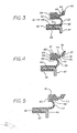
- Figures 3,4 and 5 are cross-sectional views of the seal and illustrating the rolling action of the diaphragm in response to relative axial displacement between the shaft and housing of Figures 1 and 2;
- Figure 6 is a somewhat perspective view of a preferred form of seal according to the invention;
- Figure 7 is a cross-sectional view taken about lines 7-7 of Figure 6;
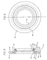
- Figure 8 is a front view in elevation of a preferred form of thrust bearing unit; and
- Figure 9 is a cross-sectional view of the thrust bearing unit shown in Figure 8;
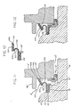
- Figure 10 is a cross-sectional view of another preferred form of seal;
- Figure 11 is a cross-sectional view of the preferred form of seal of Figure 10 installed between the spindle housing and axle shaft of a motor vehicle; and
- Figure l2 is a cross-sectional view of the embodiment of Figures 10 and 11 illustrating the relative movement between parts when the shaft is axially displaced with respect to the spindle housing.
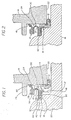
- There is shown by way of illustrative example in Figures 1 and 2 one preferred form of
seal assembly 8 broadly comprised of a rotaryfacial seal 10 and athrust bearing unit 12 interposed between two inner and outer spaced, relatively moving members, 14,16. As a setting for the present invention, theseal assembly 8 is shown installed between an outerstationary spindle housing 14 and an inner drive shaft oraxle 16 of a motor vehicle. Theaxle 16 terminates at its outboard end in aradial surface portion 17, axially directedshoulder 18 and enlargedend 20. Conventionally, thespindle housing 14 has aninner bore 22 in outer spaced facing relation to theshaft 16, a radially extendingwall surface 24, also referred to as an axial face or counterface, in facing relation to theradial wall 17 of theshaft 16 and acircular flange 26 projecting outwardly from the outboard end of thehousing 14. - Preferably the
shaft 16 has a linear axis about which it may rotate, and thespindle housing bore 22 is located about part of the shaft such that the bore and shaft are concentric or substantially concentric. In a sense, then, thespindle housing 14 may be at least partly concentric with the shaft. Precise concentricity is not necessarily a restriction for proper use and operation of the invention; indeed concentricity ordinarily would not be required for use and operation of the invention. - In the above setting, the
facial seal 10 is so mounted between thespindle housing 14 andshaft 16 as to prevent ingress of dust, water or other contaminants into the space or area between thehousing 14 andshaft 16 and at the same time to prevent the migration of lubricant, such as grease, out of that area. In establishing an effective seal, thefacial seal 10 is capable of compensating for liberal end-play and shaft misalignment as well as a lesser degree of axial biasing when the shaft is either rotating or not rotating in relation to thehousing 14. Moreover, thefacial seal 10 has been found to be effective under negative pressure to hold relatively securely against the axial face orcounterface 24 thereby maintaining the integrity of the seal. - The overall construction and arrangement of the
seal 10 may be best seen from a consideration of Figures 6 and 7, theseal 10 comprising adiaphragm 30 of elastomeric or rubber or rubber-like material having aninner seating portion 32, a generally toroidalshaped wall section 33 and outerconcentric seal body 34. The innerconcentric seating portion 32 is affixed to aring member 36, which is relatively more rigid than the diaphragm so that when theseal 10 is installed onto theshaft 16 as shown in Figures 1 and 2 in a manner to be described, theseating portion 32 is compressed between therigid ring 36 and theshaft 16. An outerbacking ring member 38 also is a rigid member which is permanently affixed to theseal body 34 in outer spaced concentric relation to theinner seating portion 32 and functions to maintain the integrity of the seal body, and acts as a directional fulcrum through which the force imparted from translational or rolling movement of thewall 33 is applied viaseal body 34 to atapered seal lip 40 at the end of theseal body 34 which is in facing relation to thespindle housing 14 as shown in Figures 1 and 2. In other words, thetoroidal wall section 33 is capable of axially loading or biasing theseal lip 40 against thespindle housing 14 when axial or translational movement occurs between theshaft 16 andhousing 14 without the aid of separate biasing or spring elements. - The necessary resilience is incorporated into the toroidal shaped,
flexible wall 33 of the diaphragm so as to act very much in the manner of a cantilever in yieldingly urging theseal lip 40 into constant engagement with the radial wall of thespindle housing 14 notwithstanding axial movement between theshaft 16 andhousing 14. The free, or relaxed, state of thewall section 33 is shown in Figure 5; i.e., thewall section 33 is molded into a configuration such that, as it advances toward the relationship shown in Figure 3, it will store an increasing biasing force tending to return it to the position shown in Figure 5. The combination of the biasing force built into thewall section 33 and rolling action of the diaphragm will cause, in combination with the limitations or constraint imparted by thebacking ring 38, that biasing force to be exerted in an axial direction upon theseal lip 40. - Referring in more detail to the construction and arrangement of elements comprising the
seal 10, and with specific reference to Figures 3 to 5, preferably theseating portion 32 defines one side or leg of a generally U-shaped innerterminal end section 42 of thediaphragm 30, the opposite side orleg 44 defining an axially directed, outboard continuation of the toroidal shapedwall section 33, and aclosed end 46 of thesection 42 joining theseating portion 32 andleg 44. - The
rigid ring 36 is of generally L-shaped cross-section and is preferably composed of a rigid metal material including anaxially extending flange 46 inserted through the open end of theU-shaped section 42 and a radially inwardly directedflange 47 at one end of theflange 46. Preferably, thering 36 is mechanically held in place and united with theseating portion 32 by forming a series of holes or bores 48 through which the elastomeric material of thediaphragm 30 flows during the molding process of the diaphragm. Mechanical bonding in the manner described avoids necessity of chemical bonding and enables thering 36 to be united with theinner seating portion 32 andinner leg 44 during the molding or curing process. - Construction of the
seating portion 32 andring 36 in the manner described greatly facilitates installation of the diaphragm onto the shaft with the inwardly directedflange 47 bearing against theradial wall 17 of the shaft. No special surfaces are required for the shaft or mating surface of the ring and no special tools required for the installation of the seal onto theshaft 16. Thefacial seal 10 simply may be pushed onto theshaft 16 until thering 36 and itsflange 47 are advanced into abutting relation with theshoulder 18 andradial wall 17; and when theseal 10 is fully seated on theshaft 16 theinner seating portion 32 is compressed between thering 36 and theshaft 16. - The
wall section 33 will undergo a rolling action as it flexes in response to relative movement between the outer and innerconcentric members wall section 33 is of generally toroidal or concavo-convex configuration with its convex wall surface in facing relation to theouter member 14. Further, the wall section is of uniform thickness in extending from theinner leg 44 across the generally circular or arcuate wail proper, as designated at 33, into an axially extending, outer concentric end orleg 52. Theouter end 52 of thewall 33 is integrally united to the outboard end of theseal body 34 and is free to roll alonginner surface 56 of the seal body in response to translational or axial movement of theshaft 16 as described. Again, in order to impart the necessary biasing action to theseal lip 40, thediaphragm 30 is molded so that in its relaxed state it is in the inboard extended position shown in Figure 5. Specifically, the outer peripheral end orleg 52 of thewall section 33 is joined to the seal body at an angle such that movement of theinner seating portion 32 in an axial direction toward the radial wall, as noted in the succession of movement illustrated in Figures 4 and 3 will cause theouter end 52 to roll outwardly along the inner circumferential surface of the seal body. Conversely, as theinner seating portion 32 is moved axially away from the radial wall toward the extended position shown in Figure 5, theouter end 52 will continue to yieldingly urge theseal lip 40 against the radial wall. This biasing force exerted by theouter end 52 is assisted by the resiliency or biasing action of theentire wall section 33 and inner leg or end 44. - The
seal body 34 preferably is in the form of a solid, generally rectangular solid block of a greater radial thickness than the remainder of the body to be described so as to be relatively inflexible with respect to the sealinglip 40. Thebacking ring 38 is of generally L-shaped cross-section and is molded into thebody 34 with axially directedflange 61 molded into an outercircumferential surface 62 of the block andflange 63 molded into radially directedoutboard end surface 64 of the block. As previously noted, thebacking ring 38 is a rigid member to maintain the integrity or uniformity of the diameter of the seal body and to act as a directional fulcrum through which the force imparted from rolling of thewall section 33 is directed into the face of theseal lip 40. Theseal body 34 converges at the end opposite to thebacking ring 38 into a hingedsection 66 and thereafter continues into taperedsection 68 which terminates in the sealinglip 40. Preferably, the hingedsection 66 is defined byinclined surfaces intersection 73. Hinging occurs at theintersection 73 of thesurfaces radius 74 which is offset slightly outboard of thehinge line 73. An outercircumferential surface 76 inclines radially and outwardly to intersect with a radially outwardly directedsurface 77 and converge at the sealinglip 40 as illustrated. The combination of the location of thehinge line 73 and groove 74 permits radially outward flaring of theseal lip 40 about thehinge 73 when thelip 40 bears against the sealing interface defined by theradial wall 24 of the spindle housing. This outward hinging or flaring also acts as a secondary means of loading theseal lip 40 axially in the same fashion as a spring would act to direct force in a linear or axial direction. Thesurface 77 adjacent to the sealinglip 40 is inclined at a steep radial angle so as to define a thin band of sealing contact when flared outwardly as described and enables the sealing force to be spread over a broad surface area on theradial wall 24 of thehousing 14. By spreading the force over a broader surface area, the seal lip is capable of running at high speeds with minimal heat build-up and wear on thesurface 77, and the axial biasing action of the diaphragm enhances sealing contact along the entire circumferential surface of the sealing lip with theradial wall surface 24. Any increased biasing force or pressure exerted upon the seal lip, as theinner seating portion 32 is axially advanced toward the radial wall is accommodated by the outward flaring or hinging action of the seal lip about thehinge line 73. - As illustrated in detail in Figures 8 and 9, a preferred form of thrust bearing 12 is of generally annular configuration and is mounted at the inner bore of the spindle housing in sealed relation to the
shaft 16 and in journaled relation to thehousing 14. Thethrust bearing 12 comprises aseal retainer ring 80 having a radially inwardly directedend flange 81 and a radially outwardly directedend flange 82 at the opposite end of thering 80. Anannular seal 83 includes aseal lip 84 at its inner radial end and an endlesscoiled spring member 85 in outer surrounding relation to the seal which acts to compress the seal in an inward radial direction against the surface of theshaft 16. A bearingmember 86 is composed of a hard, rugged plastic material, such as, an internally lubricated Nylon composition characterized by having a low dynamic coefficieint of friction. The bearingmember 86 is given a cross-sectional configuration complementary to that of thering 47 andwall 17 so that when the end of theshaft 16 moves against the bearingmember 86, it will bear against theoutboard surfaces member 86 against theradial wall 24 of thehousing 14, and prevent direct frictional contact between theshaft 16 and thespindle housing 14. To this end, the bearingmember 86 includes an outboard surface having aradially extending portion 87 andshoulder portion 88 with a steppedsurfact 89 therebetween and an innerradial end 90 which is chamfered so as to act as a guide in centering theshaft 16 when the shaft is installed within thebearing 12. By centering and guiding theshaft 16 into proper position, theseal 83 is protected from damage and thespring 85 is protected from displacement with respect to theseal 83.Inboard surface 94 of the bearingmember 86 is provided with acircular groove 92 having aslight overhang 93 for snapfit insertion of the outwardly directedflange 88 on thering 80 so that the bearingmember 86 is journaled on thering 80 and is free to spin or rotate with respect to the rest of the bearing assembly. While acting as a bearing, it is beneficial for the bearingmember 86 to be able to spin freely in relation to the seal portion of the assembly, which is mounted in fixed relation to the spindle housing, so that the force of friction exerted by the end of the shaft will be applied directly to the bearing surfaces 87 and 88 as well as toinboard surface 94. Being free to rotate with respect to the spindle housing, the bearingmember 86 will therefore rotate with, but at a lesser speed than, the rotational speed of the shaft. - The
thrust bearing assembly 12 as described is advanced into pressfit engagement within thebore 22 of the spindle housing, preferably with the assistance of a flat tool which is pressed against the outboard surface of the bearingmember 86 to force theretainer ring 80 uniformly into snug-fitting engagement with the surface of the inner bore. In this way, the bearing 12 can be installed without direct engagement with theseal 83. Moreover, as described, the bearingmember 86 effectively encloses or protects thespring member 85 backing theseal 83 and protects it from displacement during installation into the bore. - Referring to the preferred embodiment illustrated in Figures 10 to 12, like parts are correspondingly enumerated to those of the seal assembly as illustrated in Figures 1 to 8. Thus, a modified form of
seal assembly 8′ comprises a rotaryfacial seal 100 and athurst bearing unit 12′ interposed between themembers 14′ and 16′, themember 14′ again designating an outer stationary spindle housing andmember 16′ designating an inner drive shaft having aradial surface 17′,shoulder 18′ andenlarged end 20′.Housing member 14′ has aninner bore 22′,radial wall surface 24′ andcircular flange 26′. - The
facial seal 100 again comprises adiaphragm 102 of elastomeric material having aninner seating portion 32′, a generally toroidal shapedwall section 33′ and anouter seal body 104. The seatingportion 32′ is affixed to aring member 36′ in a manner corresponding to that of the form ofseal 10 shown in Figures 1 and 2, and the toroidal-shapedwall section 33′ is constructed and arranged in a manner corresponding to that of thewall section 33 of theseal 10 for the purpose of yieldingly urging theouter seal body 104 into constant engagement with theradial wall 24′ of thehousing 14′ notwithstanding axial displacement of thehousing 14′ and theshaft 16′. - An important feature of the form of invention shown in Figures 10 to 12 is the modified construction of the
outer seal body 104 so as to be of substantially uniform cross-sectional thickness throughout, except for atapered surface portion 106 which terminates in aseal lip 108 at the free end of theseal body 104 opposite to connectingend 110. As shown, thesurface portion 106 inclines at a low gradual angle away from the inner circumferential wall surface of the seal body until it intersects with the outer circumferential wall surface. The connectingend 110 is integrally formed with the outer end orleg 52′ of thetoroidal wall section 33′, and the thickness at the connectingend 110 is increased by that of theleg 52′, and is greater than that of thetoroidal wall section 33′ so as to be relatively inflexible with respect to thetoroidal section 33′. The seal body as described has sufficient integrity at its connection to thetoroidal wall section 33′ so as to act as a directional fulcrum through which the force imparted by the rolling action of thewall section 33′ can be directed into the face of theseal lip 108 without requiring a backing ring, such as, thebacking ring 38 as shown in Figures 1 to 8. - In order to impart the necessary biasing action to the
seal lip 108, theentire diaphragm 102 is molded so that in its relaxed state it will assume the inboard extended position shown in Figure 11 with theseal body 104 diverging slightly in an outward radial direction from the connectingend 104 to the oppositefree end portion 106. Movement of theinner seating portion 32′ axially towards theradial wall 24′, as noted in Figure l2, will cause thewall section 33′ to roll in an outboard direction away from the face orwall 24′ along the innercircumferential surface 112 of theseal body 104. Conversely as theinner seating portion 32 is moved axially away from thewall 24′ toward the position shown in Figure 1, thewall section 33′ and itsouter end 52′ will continue to yieldingly urge theseal lip 108 against thewall 24′. - In applications requiring high speeds of rotation between the relatively moving members, in the absence of a rigid backing ring, such as, the
backing ring 38 referred to in connection with Figures 1 to 8, the frictional wear and heat build up are reduced while maintaining the necessary loading on the seal lip for uniform contact with theradial wall surface 24′. Also the seal body is free to follow the rolling action of thtoroidal wall section 33′ under axial displacement as well as misalignment and endplay between themembers 14′ and 16′ while continuing to urge the sealing lip into a thin annular band of contact with theradial wall 24′. - The design and construction of the rotary
facial seal assemblies shaft seal assembly shaft ring inner seating portion shaft 16′. In this regard, it will be evident that theinner seating portion ring entire diaphragm diaphragm - It is therefore to be understood that while preferred embodiments of a seal and bearing assembly have been described, various modifications and changes may be made in the construction and arrangement of each together with the specific composition of materials employed therein without departing from the spirit and scope of the present invention as defined by the following claims.
Claims (26)
an annular diaphragm having a seating portion disposed around said inner member in sealing engagement therewith, an outer circumferentially extending seal lip, and resilient means defined by a generally toroidal shaped wall section of resilient deformable material extending between said seating portion and said seal lip to yieldingly urge said seal lip against said circumferential surface of said outer member notwithstanding relative movement between said inner and outer relatively movable members.
an annular diaphragm composed of elastomeric material having an inner seating portion disposed concentrically around said shaft, an outer circumferentially extending seal body including a seal lip in facing relation to said radial wall, and an annular resilient wall section extending between said seating portion and said seal lip, said diaphragm including resilient means to yieldingly urge said seal lip against said radial wall of said housing notwithstanding axial movement of said shaft with respect to said housing, said seal lip projecting in an axial direction away from said seal body into sealing engagement with said radial wall, and a circumferential hinge section of reduced thickness extending intermediately between said seal body and said seal lip.
an annular diaphragm composed of elastomeric material having an inner seating portion disposed concentrically around and in fixed sealing engagement with said shaft, an outer, circumferentially extending seal body including a seal lip, and an annular resilient wall section extending between said seating portion and said seal lip, said diaphragm including means to yieldingly urge said seal lip against said radial wall of said housing notwithstanding axial movement of said shaft with respect to said housing, and an annular bearing member disposed in abutting relation to said radial wall and in inner spaced concentric relation to said seal lip, said bearing member being axially spaced in facing relation to said inner seating portion, and means mounting said bearing member in journaled relation to said outer member.
retainer means for endwise insertion into said bore in fixed relation to said outer member and having a portion projecting axially beyond said radial wall surface toward said enlarged end; and
an annular thurst bearing member including means mounting said bearing member in journaled relation to on said projecting portion and extending in a radial and outward direction in front of said radial wall surface.
Applications Claiming Priority (4)
| Application Number | Priority Date | Filing Date | Title |
|---|---|---|---|
| US13277187A | 1987-12-14 | 1987-12-14 | |
| US132771 | 1987-12-14 | ||
| US07/282,683 US4968044A (en) | 1987-12-14 | 1988-12-08 | Rotary facial seal and bearing assembly |
| US282683 | 1988-12-12 |
Publications (3)
| Publication Number | Publication Date |
|---|---|
| EP0321200A2 true EP0321200A2 (en) | 1989-06-21 |
| EP0321200A3 EP0321200A3 (en) | 1989-10-04 |
| EP0321200B1 EP0321200B1 (en) | 1993-10-20 |
Family
ID=26830716
Family Applications (1)
| Application Number | Title | Priority Date | Filing Date |
|---|---|---|---|
| EP88311814A Expired - Lifetime EP0321200B1 (en) | 1987-12-14 | 1988-12-14 | Rotary facial seal and bearing assembly |
Country Status (3)
| Country | Link |
|---|---|
| US (1) | US4968044A (en) |
| EP (1) | EP0321200B1 (en) |
| DE (1) | DE3885070T2 (en) |
Cited By (4)
| Publication number | Priority date | Publication date | Assignee | Title |
|---|---|---|---|---|
| US5018749A (en) * | 1988-09-01 | 1991-05-28 | Firma Carl Freudenberg | Slide ring seal |
| WO1997016662A1 (en) * | 1995-10-31 | 1997-05-09 | The Timken Company | Multibarrier seal |
| EP0844420A1 (en) * | 1996-11-26 | 1998-05-27 | Gregory H. Petrak | Unitary oil seal assembly |
| US9816566B2 (en) * | 2014-03-17 | 2017-11-14 | Spicer Gelenkwellenbau Gmbh | Seal and cross member unit for universal joints |
Families Citing this family (26)
| Publication number | Priority date | Publication date | Assignee | Title |
|---|---|---|---|---|
| FR2684423B1 (en) * | 1991-11-29 | 1996-06-14 | Ardepa | SEAL FOR MOBILE SHAFT AND SEALING PART COMPRISING SUCH A SEAL. |
| DE4412132C5 (en) * | 1994-04-08 | 2005-07-28 | Ina-Schaeffler Kg | Sealing for a universal joint box |
| GB9916373D0 (en) * | 1999-07-14 | 1999-09-15 | Kvaerner Metals Davy Ltd | Seal element |
| US20020060745A1 (en) * | 2000-07-28 | 2002-05-23 | Philips Electronics North America Corporation | Outdoor dome |
| ITTO20010350A1 (en) * | 2001-04-11 | 2001-07-11 | Skf Ind Spa | STATIC SEALING ELEMENT FOR BEARINGS. |
| JP4180829B2 (en) * | 2002-01-21 | 2008-11-12 | イーグル工業株式会社 | Sealing device |
| US8336887B2 (en) * | 2006-05-02 | 2012-12-25 | Petrak Gregory H | Seal assembly |
| US8398089B2 (en) * | 2009-01-28 | 2013-03-19 | Federal-Mogul Corporation | Radial shaft seal, radial shaft seal assembly and method of installation |
| IT1397128B1 (en) * | 2009-06-25 | 2013-01-04 | Carpigiani Group Ali Spa | SEALING DEVICE FOR GRANITORS. |
| US8783393B2 (en) * | 2011-02-25 | 2014-07-22 | Deere & Company | Interface for a motor and drive assembly |
| US9062773B2 (en) | 2011-03-08 | 2015-06-23 | Federal-Mogul Corporation | Radial shaft seal, radial shaft seal assembly and method of installation |
| CN104379952B (en) * | 2012-03-20 | 2018-03-23 | 舍弗勒技术股份两合公司 | Sealed bearings with compact static outer diameter seals |
| US9169929B2 (en) | 2013-03-15 | 2015-10-27 | Little Engine, LLC | Conformal wear-resistant seal |
| WO2015061241A1 (en) * | 2013-10-23 | 2015-04-30 | Borgwarner Inc. | Actuation pivot shaft face seal with u seal |
| CN105782447B (en) * | 2014-12-25 | 2019-06-14 | 斯凯孚公司 | shaft seal |
| EP3267079B1 (en) * | 2016-07-08 | 2022-06-22 | Goodrich Actuation Systems Limited | Rotary sealing arrangement |
| US10527173B2 (en) | 2017-08-15 | 2020-01-07 | Aktiebolaget Skf | Resilient shaft seal |
| US20200032911A1 (en) * | 2018-07-26 | 2020-01-30 | Caterpillar Inc. | Metal Face Seal With Exclusion System |
| US10468812B1 (en) * | 2018-10-12 | 2019-11-05 | Getac Technology Corporation | Electrical connector structure and waterproof ring thereof |
| US11454323B2 (en) * | 2018-12-04 | 2022-09-27 | Cnh Industrial America Llc | Sealing system for a moving shaft |
| EP3730822B1 (en) * | 2019-04-23 | 2023-07-12 | Vitesco Technologies GmbH | Seal assembly and fluid valve |
| CN211344017U (en) * | 2019-12-03 | 2020-08-25 | 东莞富强电子有限公司 | Waterproof sealing ring for electric connector |
| US12013039B2 (en) * | 2020-04-06 | 2024-06-18 | Raytheon Company | Compact low friction high temperature shaft seal and attachment |
| KR102819811B1 (en) * | 2020-04-20 | 2025-06-12 | 엘에스엠트론 주식회사 | Receptacle Connector |
| EP3991918A1 (en) * | 2020-10-28 | 2022-05-04 | Hilti Aktiengesellschaft | Sealing geometry for a mobile machine tool |
| CN114909475B (en) * | 2022-04-19 | 2024-09-20 | 中铁工程装备集团有限公司 | Main drive sealing structure |
Family Cites Families (35)
| Publication number | Priority date | Publication date | Assignee | Title |
|---|---|---|---|---|
| US3125347A (en) * | 1964-03-17 | Relatively rotatable face seal with flexible backing member | ||
| CA464974A (en) * | 1950-05-09 | Stanley Morgan John | Gland for rotary shafts | |
| US2399764A (en) * | 1938-03-04 | 1946-05-07 | Gen Motors Corp | Fluid sealing device |
| US2482029A (en) * | 1946-08-05 | 1949-09-13 | Noel S Reynolds | Seal |
| FR1013310A (en) * | 1950-02-27 | 1952-07-28 | Comp Generale Electricite | Deformable seal |
| FR1024718A (en) * | 1950-09-19 | 1953-04-07 | Joint Francais | Improvements to packings for shutters |
| US2635907A (en) * | 1950-11-13 | 1953-04-21 | Brummer Mfg Corp | Seal for shafts |
| US2926938A (en) * | 1953-06-03 | 1960-03-01 | Chicago Rawhide Mfg Co | Oil seal |
| IT527712A (en) * | 1953-06-08 | |||
| FR1168769A (en) * | 1957-03-04 | 1958-12-16 | Curty & Cie | Axially thrust seal ring for rotary member |
| US2994547A (en) * | 1958-03-26 | 1961-08-01 | Muskegon Piston Ring Co Inc | Seal |
| US3120959A (en) * | 1961-02-27 | 1964-02-11 | Gits Bros Mfg Co | Unitized face type rotary seal |
| US3250540A (en) * | 1961-11-06 | 1966-05-10 | Federal Mogul Corp | Face seal |
| US3326559A (en) * | 1964-08-13 | 1967-06-20 | Joseph A Fenlon | Rotary seals |
| US3370856A (en) * | 1965-01-05 | 1968-02-27 | Textron Inc | Fluid seals for abrasive material |
| US3495843A (en) * | 1967-04-17 | 1970-02-17 | Chicago Rawhide Mfg Co | Pressure seal with antiextrusion means |
| US3642335A (en) * | 1969-09-12 | 1972-02-15 | Nippon Seiko Kk | Sealed bearing |
| US3606363A (en) * | 1969-12-23 | 1971-09-20 | Bethlehem Steel Corp | Internally threaded seal |
| DE2215041C3 (en) * | 1971-03-29 | 1982-04-29 | Karl Gustav Einar Partille Derman | Securing and sealing element |
| US3727923A (en) * | 1971-11-05 | 1973-04-17 | Gen Motors Corp | Double life shaft seal |
| BE794974A (en) * | 1972-05-08 | 1973-05-29 | Int De Soc | SEAL BETWEEN A ROTARY SHAFT AND A WALL THROUGH THIS SHAFT |
| DE2549465A1 (en) * | 1975-11-05 | 1977-05-18 | Acla Werke Ag | Annular seal for rolling bearing - deforms on assembly of one portion to impart sealing force to other portion |
| GB1559312A (en) * | 1976-08-26 | 1980-01-16 | Philips Nv | Photosensitive device arrangements and systems and photosensitive elements therefor |
| US4457519A (en) * | 1977-12-12 | 1984-07-03 | Harrington George H | Sealing ring |
| JPS551447A (en) * | 1978-06-21 | 1980-01-08 | Arai Pump Mfg Co Ltd | Seal ring for multiple end surface |
| US4171819A (en) * | 1978-08-28 | 1979-10-23 | Stoelting, Inc. | Seal for frozen confection freezer |
| BR7909018A (en) * | 1979-07-16 | 1981-05-05 | Caterpillar Tractor Co | SEALING |
| CA1136665A (en) * | 1979-11-27 | 1982-11-30 | Ernst A. Kronenberg | Shaft seal of the type incorporating a sealing flange |
| US4251082A (en) * | 1980-01-21 | 1981-02-17 | Caterpillar Tractor Co. | Joint seal having force transfer ring |
| US4284281A (en) * | 1980-02-19 | 1981-08-18 | Caterpillar Tractor Co. | Joint sealing structure |
| FR2518210B2 (en) * | 1981-04-10 | 1986-04-04 | Cefilac | DYNAMIC SEAL FOR SEALING A SHAFT THROUGH A WALL |
| DE3226875C2 (en) * | 1982-07-17 | 1984-09-06 | Wavin B.V., Zwolle | Sealing ring |
| US4502698A (en) * | 1984-07-20 | 1985-03-05 | P And C Engineering And Development | Rotary face seal with flexible annular boot |
| US4588195A (en) * | 1985-11-22 | 1986-05-13 | Dana Corporation | Floating lip seal assembly with convoluted flexible section |
| US4763905A (en) * | 1987-12-04 | 1988-08-16 | Allied-Signal Inc. | Seal retention and anti-rotation locking assembly |
-
1988
- 1988-12-08 US US07/282,683 patent/US4968044A/en not_active Expired - Lifetime
- 1988-12-14 EP EP88311814A patent/EP0321200B1/en not_active Expired - Lifetime
- 1988-12-14 DE DE3885070T patent/DE3885070T2/en not_active Expired - Fee Related
Cited By (5)
| Publication number | Priority date | Publication date | Assignee | Title |
|---|---|---|---|---|
| US5018749A (en) * | 1988-09-01 | 1991-05-28 | Firma Carl Freudenberg | Slide ring seal |
| WO1997016662A1 (en) * | 1995-10-31 | 1997-05-09 | The Timken Company | Multibarrier seal |
| US5813675A (en) * | 1995-10-31 | 1998-09-29 | The Timken Company | Multibarrier seal |
| EP0844420A1 (en) * | 1996-11-26 | 1998-05-27 | Gregory H. Petrak | Unitary oil seal assembly |
| US9816566B2 (en) * | 2014-03-17 | 2017-11-14 | Spicer Gelenkwellenbau Gmbh | Seal and cross member unit for universal joints |
Also Published As
| Publication number | Publication date |
|---|---|
| EP0321200A3 (en) | 1989-10-04 |
| EP0321200B1 (en) | 1993-10-20 |
| DE3885070T2 (en) | 1994-05-11 |
| US4968044A (en) | 1990-11-06 |
| DE3885070D1 (en) | 1993-11-25 |
Similar Documents
| Publication | Publication Date | Title |
|---|---|---|
| US4968044A (en) | Rotary facial seal and bearing assembly | |
| US20030006563A1 (en) | Rotary facial seal and bearing assembly with plastic ring | |
| US4380416A (en) | Centrifugal pumps | |
| US4874349A (en) | Seal and dust guard assembly for a universal joint trunnion | |
| US4043620A (en) | Rib-mounted bearing seal | |
| US5957461A (en) | Radial lip shaft seal | |
| US4596394A (en) | Cartridge seal | |
| US4962936A (en) | Sealing unit | |
| US4126317A (en) | Seal for installing seal over splined shaft | |
| US4026563A (en) | Oil seal with locking bead and O. D. sealing rib | |
| AU717581B2 (en) | End face seal with sacrificial wear-in excluder | |
| EP0227282B1 (en) | Unitized face sealing device | |
| US4166627A (en) | Thrust washer and combination seal and thrust washer | |
| US6077166A (en) | Dust guard and cross assembly for a universal joint | |
| US5207436A (en) | Low friction unitized seal | |
| US4733978A (en) | Contact type flexible seal for bearings | |
| US5865678A (en) | Two-piece thrust washer for universal joint | |
| US4268040A (en) | Thrust washer and combination seal and thrust washer method and apparatus | |
| US3923351A (en) | Integral bearing seal | |
| US5653449A (en) | Seal assembly | |
| US4632576A (en) | Bearing units | |
| US4502698A (en) | Rotary face seal with flexible annular boot | |
| JP2605197Y2 (en) | Sealing device | |
| US6416226B1 (en) | Preloaded cushioned bearing assembly | |
| US4752149A (en) | Pretensioned ball and socket joint |
Legal Events
| Date | Code | Title | Description |
|---|---|---|---|
| PUAI | Public reference made under article 153(3) epc to a published international application that has entered the european phase |
Free format text: ORIGINAL CODE: 0009012 |
|
| AK | Designated contracting states |
Kind code of ref document: A2 Designated state(s): DE FR GB IT SE |
|
| PUAL | Search report despatched |
Free format text: ORIGINAL CODE: 0009013 |
|
| AK | Designated contracting states |
Kind code of ref document: A3 Designated state(s): DE FR GB IT SE |
|
| 17P | Request for examination filed |
Effective date: 19900402 |
|
| 17Q | First examination report despatched |
Effective date: 19911023 |
|
| GRAA | (expected) grant |
Free format text: ORIGINAL CODE: 0009210 |
|
| AK | Designated contracting states |
Kind code of ref document: B1 Designated state(s): DE FR GB IT SE |
|
| REF | Corresponds to: |
Ref document number: 3885070 Country of ref document: DE Date of ref document: 19931125 |
|
| ITF | It: translation for a ep patent filed | ||
| ET | Fr: translation filed | ||
| PLBE | No opposition filed within time limit |
Free format text: ORIGINAL CODE: 0009261 |
|
| STAA | Information on the status of an ep patent application or granted ep patent |
Free format text: STATUS: NO OPPOSITION FILED WITHIN TIME LIMIT |
|
| 26N | No opposition filed | ||
| EAL | Se: european patent in force in sweden |
Ref document number: 88311814.3 |
|
| REG | Reference to a national code |
Ref country code: GB Ref legal event code: IF02 |
|
| PGFP | Annual fee paid to national office [announced via postgrant information from national office to epo] |
Ref country code: GB Payment date: 20031217 Year of fee payment: 16 |
|
| PGFP | Annual fee paid to national office [announced via postgrant information from national office to epo] |
Ref country code: FR Payment date: 20031223 Year of fee payment: 16 |
|
| PGFP | Annual fee paid to national office [announced via postgrant information from national office to epo] |
Ref country code: SE Payment date: 20031229 Year of fee payment: 16 Ref country code: DE Payment date: 20031229 Year of fee payment: 16 |
|
| PG25 | Lapsed in a contracting state [announced via postgrant information from national office to epo] |
Ref country code: GB Free format text: LAPSE BECAUSE OF NON-PAYMENT OF DUE FEES Effective date: 20041214 |
|
| PG25 | Lapsed in a contracting state [announced via postgrant information from national office to epo] |
Ref country code: SE Free format text: LAPSE BECAUSE OF NON-PAYMENT OF DUE FEES Effective date: 20041215 |
|
| PG25 | Lapsed in a contracting state [announced via postgrant information from national office to epo] |
Ref country code: DE Free format text: LAPSE BECAUSE OF NON-PAYMENT OF DUE FEES Effective date: 20050701 |
|
| EUG | Se: european patent has lapsed | ||
| GBPC | Gb: european patent ceased through non-payment of renewal fee |
Effective date: 20041214 |
|
| PG25 | Lapsed in a contracting state [announced via postgrant information from national office to epo] |
Ref country code: FR Free format text: LAPSE BECAUSE OF NON-PAYMENT OF DUE FEES Effective date: 20050831 |
|
| REG | Reference to a national code |
Ref country code: FR Ref legal event code: ST |
|
| PG25 | Lapsed in a contracting state [announced via postgrant information from national office to epo] |
Ref country code: IT Free format text: LAPSE BECAUSE OF NON-PAYMENT OF DUE FEES;WARNING: LAPSES OF ITALIAN PATENTS WITH EFFECTIVE DATE BEFORE 2007 MAY HAVE OCCURRED AT ANY TIME BEFORE 2007. THE CORRECT EFFECTIVE DATE MAY BE DIFFERENT FROM THE ONE RECORDED. Effective date: 20051214 |