EP0321178A1 - Gelenkmechanismus - Google Patents
Gelenkmechanismus Download PDFInfo
- Publication number
- EP0321178A1 EP0321178A1 EP88311766A EP88311766A EP0321178A1 EP 0321178 A1 EP0321178 A1 EP 0321178A1 EP 88311766 A EP88311766 A EP 88311766A EP 88311766 A EP88311766 A EP 88311766A EP 0321178 A1 EP0321178 A1 EP 0321178A1
- Authority
- EP
- European Patent Office
- Prior art keywords
- socket
- joint according
- pintle
- movable member
- spring
- Prior art date
- Legal status (The legal status is an assumption and is not a legal conclusion. Google has not performed a legal analysis and makes no representation as to the accuracy of the status listed.)
- Withdrawn
Links
Images


Classifications
-
- F—MECHANICAL ENGINEERING; LIGHTING; HEATING; WEAPONS; BLASTING
- F16—ENGINEERING ELEMENTS AND UNITS; GENERAL MEASURES FOR PRODUCING AND MAINTAINING EFFECTIVE FUNCTIONING OF MACHINES OR INSTALLATIONS; THERMAL INSULATION IN GENERAL
- F16F—SPRINGS; SHOCK-ABSORBERS; MEANS FOR DAMPING VIBRATION
- F16F1/00—Springs
- F16F1/36—Springs made of rubber or other material having high internal friction, e.g. thermoplastic elastomers
- F16F1/366—Springs made of rubber or other material having high internal friction, e.g. thermoplastic elastomers made of fibre-reinforced plastics, i.e. characterised by their special construction from such materials
- F16F1/368—Leaf springs
- F16F1/3683—Attachments or mountings therefor
- F16F1/3686—End mountings
-
- B—PERFORMING OPERATIONS; TRANSPORTING
- B60—VEHICLES IN GENERAL
- B60G—VEHICLE SUSPENSION ARRANGEMENTS
- B60G11/00—Resilient suspensions characterised by arrangement, location or kind of springs
- B60G11/02—Resilient suspensions characterised by arrangement, location or kind of springs having leaf springs only
- B60G11/10—Resilient suspensions characterised by arrangement, location or kind of springs having leaf springs only characterised by means specially adapted for attaching the spring to axle or sprung part of the vehicle
- B60G11/12—Links, pins, or bushes
-
- B—PERFORMING OPERATIONS; TRANSPORTING
- B60—VEHICLES IN GENERAL
- B60G—VEHICLE SUSPENSION ARRANGEMENTS
- B60G5/00—Resilient suspensions for a set of tandem wheels or axles having interrelated movements
- B60G5/04—Resilient suspensions for a set of tandem wheels or axles having interrelated movements with two or more pivoted arms, the movements of which are resiliently interrelated, e.g. the arms being rigid
- B60G5/047—Resilient suspensions for a set of tandem wheels or axles having interrelated movements with two or more pivoted arms, the movements of which are resiliently interrelated, e.g. the arms being rigid at least one arm being resilient, e.g. a leafspring
-
- B—PERFORMING OPERATIONS; TRANSPORTING
- B60—VEHICLES IN GENERAL
- B60G—VEHICLE SUSPENSION ARRANGEMENTS
- B60G7/00—Pivoted suspension arms; Accessories thereof
- B60G7/02—Attaching arms to sprung part of vehicle
-
- F—MECHANICAL ENGINEERING; LIGHTING; HEATING; WEAPONS; BLASTING
- F16—ENGINEERING ELEMENTS AND UNITS; GENERAL MEASURES FOR PRODUCING AND MAINTAINING EFFECTIVE FUNCTIONING OF MACHINES OR INSTALLATIONS; THERMAL INSULATION IN GENERAL
- F16C—SHAFTS; FLEXIBLE SHAFTS; ELEMENTS OR CRANKSHAFT MECHANISMS; ROTARY BODIES OTHER THAN GEARING ELEMENTS; BEARINGS
- F16C11/00—Pivots; Pivotal connections
- F16C11/04—Pivotal connections
-
- F—MECHANICAL ENGINEERING; LIGHTING; HEATING; WEAPONS; BLASTING
- F16—ENGINEERING ELEMENTS AND UNITS; GENERAL MEASURES FOR PRODUCING AND MAINTAINING EFFECTIVE FUNCTIONING OF MACHINES OR INSTALLATIONS; THERMAL INSULATION IN GENERAL
- F16C—SHAFTS; FLEXIBLE SHAFTS; ELEMENTS OR CRANKSHAFT MECHANISMS; ROTARY BODIES OTHER THAN GEARING ELEMENTS; BEARINGS
- F16C2326/00—Articles relating to transporting
- F16C2326/01—Parts of vehicles in general
- F16C2326/05—Vehicle suspensions, e.g. bearings, pivots or connecting rods used therein
Definitions
- the present invention relates to a hinge mechanism, particularly, though not exclusively, intended for mounting a goods road vehicle suspension arm to a suspension hanger bracket.
- the present invention provides a joint comprising a fixed member and a movable member hingedly connected to and extending from the fixed member, wherein the movable member has a body and a bulbous head defining a pintle received in a slotted socket in the fixed member with the body of the movable member protruding through the slot whose angular extent relative to adjacent portions of the body permits limited articulation of the movable member.
- the socket is defined by a first part receiving the pintle and by a second part fastened to the first part to hold the pintle in radial position relative to the fixed member.
- the socket is a single member (e.g. a casting) of C-profile and opposed ends of the socket are closed by end plate means to maintain the pintle in axial position.
- the above joint may be used for trailing arms of air suspensions for goods road vehicles, e.g. of the trailer or semi-trailer type, or may be used for carriage spring suspensions for such vehicles, or may have wider or more general uses.
- a slit bush fits between the pintle and the socket. It may be formed of an elastomer such as rubber or a low friction plastics material. It may be fitted either to the socket which is typically of steel or to the pintle which is of fibreglass. Where the socket is in two parts, they may be separated and reconnected from a radial or an axial direction. Thus the second part of the socket may be bolted into position to hold the bush and pintle in place, or it may be a part-cylindrical member which is slipped on from the side.
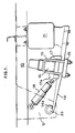
- a chassis longitudinal member 10 of a semi-trailer goods vehicle has a pair of depending hanger bracket plates 12. The plane of section passes between the hanger bracket plates so that only one of them appears in the drawing.
- a steel trailing arm 14 is pivoted at its forward end by means of an integrally formed eye 14a to a pin 23 attached between the plates 12.
- An axle 16 is attached to the trailing arm 14 through a saddle member 17 and a chair member 19 as is conventional in the art.
- a shock absorber 18 is pivoted between the nose 17a of the saddle member 17 and the hanger bracket plates 12.
- the rear end of the arm 14 is connected to the lower end of an air bag 21 whose upper end is connected to the chassis member 10.
- Figure 2 shows a conventional tandem axle suspension unit in which axles 40, 42 are attached by means of U-bolts 15 and saddle and chair members 17a, 19a to single-leaf or multi-leaf carriage springs 44, 46.
- the load from the vehicle body is transferred onto the steel springs 44, 46, by means of internal cross-plates 48 of a front hanger bracket 50, an equalizer 52 pivoted to hanger bracket 53 and a rear hanger bracket 54.
- the spring chairs 19a are connected at their noses 19b to respective front and middle hanger brackets 50, 53 by means of radius rods 55 which may be fixed or adjustable.
- the steel springs 44, 46 may be multi-leaf as shown or may be single leaf, and a similar structure is used for three-axle configuration, there being a pair of equalizers like the equalizer 52.
- a casting 22 forming the first part of a socket is welded between the hanger bracket plates 12. It is formed with a front region 24 having vertical threaded holes, a concave arcuate middle region 26 and an upwardly inclined rear or gusset region 28.
- the pintle 20 fits concentrically into the middle region 26 with an intermediate bush 30. It is preferred to make the bush 30 of elastomeric material such as a rubber so that shock loads are not transmitted into the hanger bracket plates 12 and so that limited joint flexion can take place under side loads.
- the bush 30 may be of a less flexible material such as phosphor bronze.
- the socket is completed by a curvilinear second part 32 having a front region 34 formed with through holes for retainer bolts 36 and having a concave rear region 38 that completes the socket.
- the pintle 20 is rotatably held between the socket parts 22, 32. It will be noted that these parts apply a compressive load to the pintle 20 and that their rear ends define a slit through which the body of the trailing arm 14 emerges. The width of the slit relative to the depth of the trailing arm body where it joins the pintle 20 is such as to allow limited articulation of the trailing arm 14 relative to the hanger bracket plates 12.
- the rear portion 28 of the socket part 22 defines a bluff abutment limiting over-track of the arm 14, but its main purpose is to provide further attachment between the hanger bracket plates 12 between which the casting 22 is welded as shown.
- the second form of the hinge joint ( Figure 4) is similar except that the castings 22, 32 are replaced by a single generally C-shaped socket casting 60 which is fastened as by welding or bolting beneath the hanger bracket plates 12a.
- the ends of the socket casting 60 are closed by means of cover plates (not shown) to stop sideways movement of the pintle 20 relative to the socket 60.
- a single axle suspension has an axle 70 bolted beneath a single-leaf fibreglass spring 72 which is formed at its forward end with a bulbous pintle 74.
- a front hanger bracket 76 is formed with a C-shaped socket formation 78 having an intermediate rubber bush 80 as previously described.
- the rear end of the spring 72 may simply slide through a rear hanger bracket 82 having a cross-plate 84 which rests on the spring 72 as is conventional in the art.
- the rear end of the spring 72 is formed with a second bulbous pintle 88.
- An oscillating link 90 is pivoted at 92 to the rear hanger bracket 86 and has at its lower end a C-shaped socket formation 94 in which the pintle is secured with a second bush 96 between pintle 88 and socket 94.
- the ends of the sockets 78, 94 are closed off by means of cover plates (not shown) positioned over the ends of pintles 78, 88 to stop the spring 72 from moving sideways relative to the hanger brackets 76 and 86.
- a carriage spring tandem axle suspension can be constructed on the same lines with pintles like the pintles 74 received in C-profile sockets in hanger brackets depending from the chassis structure.
- the ends of the springs 72, 72a adjacent the equalizer 90 are formed with pintles 74, 88 received in sockets 92, 94 of oscillating links 96, 98 pivoted at 99, 100 to the equalizer 90.
Landscapes
- Engineering & Computer Science (AREA)
- Mechanical Engineering (AREA)
- General Engineering & Computer Science (AREA)
- Vehicle Body Suspensions (AREA)
Applications Claiming Priority (2)
| Application Number | Priority Date | Filing Date | Title |
|---|---|---|---|
| GB8729360 | 1987-12-16 | ||
| GB878729360A GB8729360D0 (en) | 1987-12-16 | 1987-12-16 | Hinge mechanism |
Publications (1)
| Publication Number | Publication Date |
|---|---|
| EP0321178A1 true EP0321178A1 (de) | 1989-06-21 |
Family
ID=10628589
Family Applications (1)
| Application Number | Title | Priority Date | Filing Date |
|---|---|---|---|
| EP88311766A Withdrawn EP0321178A1 (de) | 1987-12-16 | 1988-12-13 | Gelenkmechanismus |
Country Status (2)
| Country | Link |
|---|---|
| EP (1) | EP0321178A1 (de) |
| GB (1) | GB8729360D0 (de) |
Cited By (5)
| Publication number | Priority date | Publication date | Assignee | Title |
|---|---|---|---|---|
| EP0773119A1 (de) * | 1995-11-09 | 1997-05-14 | Ror Rockwell Limited | Verbesserungen an einer luftgefederten Aufhängung eines Fahrzeuges |
| GB2343160A (en) * | 1998-10-30 | 2000-05-03 | Tenneco Automotive Inc | An axle shaft spacer member for use with a suspension lift kit |
| EP1197359A1 (de) * | 2000-10-13 | 2002-04-17 | General Trailers France | Aufhängungslenker und Bremsträger |
| EP1486359A3 (de) * | 2003-06-14 | 2005-04-27 | Meritor Heavy Vehicle Systems Limited | Längsarmaufhängung |
| DE102015118243A1 (de) * | 2015-10-26 | 2017-04-27 | Benteler Automobiltechnik Gmbh | Blattfederhalteelement zur Halterung einer Blattfeder |
Citations (5)
| Publication number | Priority date | Publication date | Assignee | Title |
|---|---|---|---|---|
| US1536981A (en) * | 1924-09-15 | 1925-05-05 | Elvir W Stossel | Spring connection |
| FR1100286A (fr) * | 1953-05-09 | 1955-09-19 | Daimler Benz Ag | Dispositif de suspension élastique à lames pour voitures automobiles |
| EP0005916A1 (de) * | 1978-05-26 | 1979-12-12 | GKN Group Services Limited | Herstellung von Federn |
| EP0137096A2 (de) * | 1983-09-13 | 1985-04-17 | Jörn, Frieda | Elastische Lagerung von Blattfederenden für Strassen- und Schienenfahrzeuge |
| GB2160616A (en) * | 1984-06-20 | 1985-12-24 | Gkn Technology Ltd | Securing components to composite springs |
-
1987
- 1987-12-16 GB GB878729360A patent/GB8729360D0/en active Pending
-
1988
- 1988-12-13 EP EP88311766A patent/EP0321178A1/de not_active Withdrawn
Patent Citations (5)
| Publication number | Priority date | Publication date | Assignee | Title |
|---|---|---|---|---|
| US1536981A (en) * | 1924-09-15 | 1925-05-05 | Elvir W Stossel | Spring connection |
| FR1100286A (fr) * | 1953-05-09 | 1955-09-19 | Daimler Benz Ag | Dispositif de suspension élastique à lames pour voitures automobiles |
| EP0005916A1 (de) * | 1978-05-26 | 1979-12-12 | GKN Group Services Limited | Herstellung von Federn |
| EP0137096A2 (de) * | 1983-09-13 | 1985-04-17 | Jörn, Frieda | Elastische Lagerung von Blattfederenden für Strassen- und Schienenfahrzeuge |
| GB2160616A (en) * | 1984-06-20 | 1985-12-24 | Gkn Technology Ltd | Securing components to composite springs |
Non-Patent Citations (1)
| Title |
|---|
| PATENT ABSTRACTS OF JAPAN * |
Cited By (10)
| Publication number | Priority date | Publication date | Assignee | Title |
|---|---|---|---|---|
| EP0773119A1 (de) * | 1995-11-09 | 1997-05-14 | Ror Rockwell Limited | Verbesserungen an einer luftgefederten Aufhängung eines Fahrzeuges |
| GB2343160A (en) * | 1998-10-30 | 2000-05-03 | Tenneco Automotive Inc | An axle shaft spacer member for use with a suspension lift kit |
| GB2343160B (en) * | 1998-10-30 | 2002-06-19 | Tenneco Automotive Inc | Axle shaft spacer member |
| EP1197359A1 (de) * | 2000-10-13 | 2002-04-17 | General Trailers France | Aufhängungslenker und Bremsträger |
| FR2815292A1 (fr) * | 2000-10-13 | 2002-04-19 | Gen Trailers France | Ensemble de bras de suspension et support de frein |
| EP1486359A3 (de) * | 2003-06-14 | 2005-04-27 | Meritor Heavy Vehicle Systems Limited | Längsarmaufhängung |
| CN1572547B (zh) * | 2003-06-14 | 2010-10-06 | 美驰重型车系统有限公司 | 悬挂牵引臂、悬挂总成、重型商用车辆拖车及牵引臂制造方法 |
| US7946601B2 (en) | 2003-06-14 | 2011-05-24 | Meritor Heavy Vehicle Systems Limited | Suspension trailing arm |
| DE102015118243A1 (de) * | 2015-10-26 | 2017-04-27 | Benteler Automobiltechnik Gmbh | Blattfederhalteelement zur Halterung einer Blattfeder |
| US10632809B2 (en) | 2015-10-26 | 2020-04-28 | Sgl Carbon Se | Leaf spring retaining element for a leaf spring mounting plate |
Also Published As
| Publication number | Publication date |
|---|---|
| GB8729360D0 (en) | 1988-01-27 |
Similar Documents
| Publication | Publication Date | Title |
|---|---|---|
| US5203585A (en) | Split-beam suspension system | |
| CA2147555C (en) | Stiff beam suspension system | |
| EP0863060B1 (de) | Achsaufhängungssystem | |
| US3547215A (en) | Automotive vehicle suspension structure | |
| US6460872B2 (en) | Vehicle suspension systems | |
| EP1987969B1 (de) | Schäkelanordnung | |
| US4166640A (en) | Axle suspension for wheeled vehicles | |
| EP0880440B1 (de) | Gelenkradaufhängung | |
| EP0605398B1 (de) | Fahrzeugaufhängungssystem | |
| US4750757A (en) | Rear axle torque rod damper | |
| US4705294A (en) | Air suspension assembly with universal pivoted hanger bearings and rigid mount angular torque spring-beam | |
| US6390485B1 (en) | Vehicle suspension | |
| US4422666A (en) | Suspension mechanism for automotive vehicles | |
| US5908198A (en) | Center beam suspension system | |
| US7967307B2 (en) | Heavy duty trailing arm suspension system | |
| US5458360A (en) | Tandem axle suspension with leaf spring guided forward axle suspension and torque beam guided rear axle suspension connected by a load equalizing bolster beam | |
| GB2069424A (en) | Tandem axle suspension | |
| US3990725A (en) | Independent front suspension for a motor vehicle | |
| US3504929A (en) | Two-piece equalizer bracket | |
| EP0321178A1 (de) | Gelenkmechanismus | |
| US5542652A (en) | Anti-friction pad for a bushed pivot point connection of a main leaf spring and a secondary leaf spring | |
| US3531099A (en) | Equalizer assembly | |
| GB2197268A (en) | Transverse leaf spring suspension | |
| GB2145673A (en) | Multiple axle suspension system | |
| AU703820B2 (en) | Vehicle suspension |
Legal Events
| Date | Code | Title | Description |
|---|---|---|---|
| PUAI | Public reference made under article 153(3) epc to a published international application that has entered the european phase |
Free format text: ORIGINAL CODE: 0009012 |
|
| AK | Designated contracting states |
Kind code of ref document: A1 Designated state(s): BE DE ES FR GB IT NL |
|
| 17P | Request for examination filed |
Effective date: 19891208 |
|
| 17Q | First examination report despatched |
Effective date: 19910528 |
|
| STAA | Information on the status of an ep patent application or granted ep patent |
Free format text: STATUS: THE APPLICATION IS DEEMED TO BE WITHDRAWN |
|
| 18D | Application deemed to be withdrawn |
Effective date: 19911008 |