EP0321080A2 - Modellierungssystem für Festkörper - Google Patents
Modellierungssystem für Festkörper Download PDFInfo
- Publication number
- EP0321080A2 EP0321080A2 EP88310188A EP88310188A EP0321080A2 EP 0321080 A2 EP0321080 A2 EP 0321080A2 EP 88310188 A EP88310188 A EP 88310188A EP 88310188 A EP88310188 A EP 88310188A EP 0321080 A2 EP0321080 A2 EP 0321080A2
- Authority
- EP
- European Patent Office
- Prior art keywords
- logic
- primitives
- bitmap
- primitive
- node
- Prior art date
- Legal status (The legal status is an assumption and is not a legal conclusion. Google has not performed a legal analysis and makes no representation as to the accuracy of the status listed.)
- Granted
Links
Images


Classifications
-
- G—PHYSICS
- G06—COMPUTING OR CALCULATING; COUNTING
- G06T—IMAGE DATA PROCESSING OR GENERATION, IN GENERAL
- G06T17/00—Three dimensional [3D] modelling, e.g. data description of 3D objects
- G06T17/20—Finite element generation, e.g. wire-frame surface description, tesselation
Definitions
- the present invention relates to a solid modelling system for generating a spatial representation of a three-dimensional solid object in which redundant parts of an object definition can be automatically identified and discarded.
- Objects may be represented in solid modelling systems using various techniques.
- One which is particularly suitable for representing solid objects is sometimes termed "Constructive Solid Geometry” (CSG).
- CSG Consstructive Solid Geometry
- a three-dimensional (3-D) solid object is represented by a functional definition identifying the set of points which lie within the object.
- the object is defined by a Boolean function which returns a "true” if applied to a point within the object and returns a "false” otherwise.
- This technique contrasts with, for example, line drawing techniques where the edges and surfaces of an object are defined rather than its volume.
- the functional definition of an object effectively defines the set of points which make up the object.
- the functional definition of a sphere for example, defines the set of points lying within a given radius of a centre point.
- Composite objects are defined by combining the functional definitions of basic solid objects, or "primitives”, eg spheres, half-spaces (ie. the space on one side of an infinite plane), infinite cylinders.
- dumb-bell for example, would comprise the functional definition of each of two spheres at different positions, the functional definition of an infinite cylinder whose axis passes through the centres of the spheres and the functional definitions of two planar half-spaces which truncate the cylinder at the spheres, the functional definitions of the spheres, the cylinder and the planar half spaces being combined using a logical expression including set operators such as the set union and intersect operators (ie using set theory principles). Expressions can also include other combinatorial operators such as set subtracting operators to define, for example, a composite object with a cut-out or hole. In this way hollow composite objects can be defined by subtracting a smaller object from a larger one. Such composite objects are still "solid" within the meaning of this document because points in space can be tested against the expression defining the object to determine whether they are inside or outside the object.
- a composite object formed from primitives is typically defined in terms of a structure which represents the logical expression defining the object and comprises a linked set of nodes (eg. a tree structure) with the primitives being defined at first nodes (eg. leaf nodes of the tree), operators being defined at second or intermediate nodes to identify the combinatorial operations to be performed to construct the object from the primitives and/or sub-objects defined at lower-order nodes in the structure and the composite object being defined at an appropriate one of the operator nodes (eg. the root of the tree).
- first nodes eg. leaf nodes of the tree
- operators being defined at second or intermediate nodes to identify the combinatorial operations to be performed to construct the object from the primitives and/or sub-objects defined at lower-order nodes in the structure
- the composite object being defined at an appropriate one of the operator nodes (eg. the root of the tree).
- a representation of the object with respect to space ie. a spatial representation
- the spatial representation could take various forms depending on the application.
- the spatial representation could be in the form of an image of the surface or of the edges of the object. This is often desired if the solid modelling system forms or is part of a graphics system.
- the solid modelling system could form a robotics control system for modelling a robot and its surroundings and controlling the movement of the robot or for controlling a tool during the manufacture of an item.
- the spatial representation could be used to compute data such as mass properties of the object.
- primitives which are redundant are incorporated in a CSG definition.
- a primitive is said to be 'redundant' if the CSG definition can be re-written without that primitive. This can come about when building blocks which comprise a group of primitives (eg a cube comprising six planar half-spaces), rather than the primitives themselves, are used to simplify the generation of a CSG definition.
- primitives can become redundant during evaluation of an object if the boundaries of the primitives are coextensive in a region of space (termed a voxel) being considered in the spatial subdivision process.
- each block being defined by a set of six planar half-spaces.
- the half-spaces defining the sides of the blocks are not redundant initially, they effectively cancel each other out where the sides of the cubes are co-extensive and are therefore redundant when considering the object solely in this region.
- the object of the present invention is a solid modelling system comprising means for generating a spatial representation of an object defined in terms of solid geometric primitives combined by a logical expression including one or more combinatorial logical operators, which is adapted to recognise redundant primitives automatically.
- a solid modelling system comprising means for generating a spatial representation of an object defined in terms of solid geometric primitives combined by a logical expression including one or more combinatorial logical operators, the solid modelling system comprising object definition means including a structure comprising a plurality of linked nodes including primitive nodes for the primitives and operator nodes for the operators, first logic for traversing at least certain of the nodes and for generating a bitmap representing the logical expression or the part thereof defined at the operator nodes encountered during the traversal and second logic for testing the bitmap for logical redundancies indicative of redundant geometric primitives.
- each bit in the bitmap is representative of a respective one of the constituents of the primitives, a constituent being the volume formed by the intersection of primitives or their complements, and, in order to test for the redundancy of a primitive u, the second logic tests for equivalence of the corresponding utrue and ufalse constituents in the bitmap.
- the first logic additionally generates a table of pointers to the primitives encountered during the traversal and the second logic deletes from the table a pointer to a primitive which is found to be redundant.
- Third logic is preferably provided for replacing the nodes traversed by the first logic by a single truth table node which comprises the modified bitmap produced by the second logic and pointers to nodes defining the remaining primitives.
- the particular example of a solid modelling system in accordance with the invention which is described later additionally comprises world space definition means for defining the space in which the object exists, spatial subdivision logic for subdividing world space into progressively smaller regions of space, or voxels, until voxels are created for which the spatial representation can be rendered, object simplification logic for simplifying the structure defining the object within a voxel generated by the spatial subdivision means, counting logic for counting the number of primitives remaining in the structure, or a part of a simplified structure as generated by the object simplification means and, if there are less than a predetermined number of primitives, to cause the first and second logic to process said simplified structure.
- the object simplification logic comprises logic for simplifying a bitmap generated by the first logic within a voxel generated by the spatial subdivision means.
- a solid modelling system as above can additionally comprise logic for processing a relevance map representative of geometric information for indicating when bits of the bitmap are determined to be irrelevant to the definition of the object within that voxel (eg. when the associated constituents are proved to be empty within the voxel).
- the evaluation of a solid model is the process of determining the inside and outside and thus the boundaries of the solid.
- Figure 1A is an illustration of a step-like object 10, shown within a region of space defined by a cube 20.
- Figure 1B illustrates a representation of this object in the form of two touching blocks 12 and 14, shown in cross section perpendicular to the Z axis. Both of the blocks have the same depth, from a plane at Z1 to a plane at Z2, the cross section being through a plane parallel to, but intermediate, the planes at Z1 and Z2.
- the first block 12 is defined in terms of a logical combination of six planar half spaces X1, X2, Y1, Y3, Z1 and Z2 and the second block 14 is defined in terms of a logical combination of six planar half spaces -X2, X3, Y1, Y2, Z1 and Z2.
- the arrows in Figure 1B indicate which sides of the lines shown in the Figure (the lines actually represent planes seen end on) are solid.
- the planes referred to above and also in the following form the boundaries of planar half spaces.
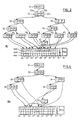
- the logical expression combining these half-spaces is defined in accordance with the principles of CSG by a structure such as that shown in Figure 2.
- the tree-shaped structure 30 shown in Figure 2 is formed from a linked set of nodes of different types.
- the intermediate, or operator nodes 32 to 43 conventionally include a first field (eg. 32a) defining a logical operator and one or more further fields containing pointers. As shown in Figure 2, a second field (eg. 32b) defines a first pointer P1 to another node and a third field (eg. 32c), if present, defines a second pointer P2 to another node.
- the operators conventionally include the Boolean operators "UNION”, “DIFFERENCE”, “INTERSECT”, “SYMMETRIC DIFFERENCE” and “COMPLEMENT", although other types of operators may also be used.
- An operator node comprises a single pointer field if the operator is a "COMPLEMENT" operator (eg. node 43) and two pointer fields otherwise.
- "U”, “I” and “C” represent "UNION”, "INTERSECT” and "COMPLEMENT” operators respectively.
- the leaf, or primitive, nodes 44 to 51 define the primitives which make up the object.
- Each of the leaf nodes comprise at least a first field (eg. 44a) containing the expression defining that primitive, a second, flag, field (eg. 44b) and a third, results, field (eg. 44c).
- the first field can be large in order to be able to incorporate the definition of that primitive.
- the second and third fields are used by simplification logic as will be explained later.
- the leaf nodes additionally comprise at least one other field as will be explained when describing that example.
- the node 31 is a pointer which is supplied to the control logic by the user program and points to the first intermediate, or root, node 32.
- a leaf node may be pointed to by more than one of the intermediate nodes if the primitive occurs in a plurality of the sub-objects defined at those intermediate nodes. If a tree is initially generated in which there may be duplicate primitive nodes, the duplication can be eliminated automatically by traversing a tree and testing for identical or complementary primitives. If identical primitives are discovered then one of the primitive nodes can be discarded and a pointer placed in each of the appropriate intermediate nodes to the retained primitive node. For example, this is the case for the primitive defined at the leaf node 45 which is pointed to by the intermediate nodes 37 and 43. If complementary primitives are detected, then the same can be done except that a COMPLEMENT node must be introduced into the structure at an appropriate position as is the case with the COMPLEMENT node 43.
- the spatial representation could take various forms depending on the CSG application.
- the spatial representation could be in the form of an image of the surface or of the edges of the object if the CSG system forms part of a graphics system. This image could be rendered in any conventional manner on a display screen, with a printer and so on.
- the spatial representation could form part of a robot's model of itself and its surroundings if the CSG system is incorporated in a robotics control system.
- the generation of a spatial representation in the form of a wire-frame image for display using a display screen, printer etc. will be described, although it should be realised that the present invention is not limited to the generation and/or rendering of wire-frame images.
- the process of evaluating a CSG representation of an object comprises subdividing a region of space in which the object exists (eg. the region 20) into progressively smaller and smaller sub-regions (eg. the eight sub-regions 21 to 28 shown in Figure 1A) and determining the relationship between the object definition and successive sub-regions until the relationship between the CSG representation and the region of space has been evaluated to an elemental level whereby the spatial distribution of the object can be determined.
- the solid modelling system comprises storage for a definition of the space (world space) in which the object exists, and subdivision logic which is responsible for the subdivision process.
- the solid modelling system also comprises control logic for controlling the operation of the subdivision and other logic in the system.
- the first step of subdividing the box-like region of space 20 is to divide it into 8 sub-regions 21, 22, 23, 24, 25, 26, 27 and 28. Subsequently, each of these sub-regions will be divided into eight further sub-regions and so on. It will be noted that the subdivision is performed in a recursive manner. A sub-region will not be subdivided further if it is determined that the sub-region is FULL, EMPTY or that the part of the object within that sub-region can be rendered (ie. reproduced) directly as will be explained below. It will be appreciated by those skilled in the art that other subdivision algorithms are possible.
- the structure representing the object is inspected and simplified, or "pruned", within the region or sub-region of space (hereinafter a voxel) under consideration.
- the simplification process is performed by simplification logic during each step in the recursive subdivision process and is itself a recursive process.
- the simplification logic processes the structure defining the object for a given voxel by testing the relationship between that voxel and the primitives identified in the structure and simplifying the structure where possible.
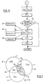
- the simplification logic is illustrated by means of a flow diagram in Figure 3.
- the simplification logic is called into action by the control logic of the solid modelling system in order to simplify the CSG expression for a new voxel.
- the control logic passes the contents of the pointer 31 (ie. the pointer to the root node 32) as an input parameter to the simplification logic.
- the simplification logic returns to the control logic a pointer to the first valid node of the simplified tree. Normally, the first valid node will be the root node 32.
- the simplification logic tests (at 55) whether the node pointed to is a leaf node or not. As explained below, if the node is a leaf node, then geometric tests are performed, whereas logical tests are performed otherwise.
- the simplification logic tests (at 56) whether the primitive node has been visited before during the current traversal by checking whether a simplification flag has been set in the flag field of the primitive node. If the flag was not set, then the simplification logic at 57) sets the flag using a number called a "visiting card", determines the relationship between the expression for the primitive at that node and the expression for the current voxel supplied by the subdivision logic, and stores the result of the determination in the result field of the primitive node.
- the result can be one of the following possibilities: EMPTY, FULL or OTHER.
- the simplification flag referred to above is a number which is unique to each traversal of the structure by the simplification logic, which avoids the need to reset all the flag fields at the start of each traversal.
- the result stored in the result field by this or a previous visit to the primitive node by SL within this voxel is used to determine the information to be returned by this call of the simplification logic. If the primitive and the voxel do not intersect, then the result EMPTY will have been stored as the result as the definition for the voxel can effectively be replaced by the value EMPTY. Consequently, in this case a pointer to a node (eg. node 52 in Figure 2) containing this definition is returned by the simplification logic. If the primitive entirely contains the voxel, then the result FULL will have been stored as the expression for the voxel can effectively be replaced by the value FULL.
- the simplification logic tests (at 59) whether the operator is a "complement" operator. If it is, the simplification logic accesses the pointer in that node to the node dependent thereon and uses that pointer for a recursive call (at 60) of the simplification logic. On return from the recursive call, the pointer returned therefrom is investigated at 61 by the simplification logic. If the pointer is to the definition "FULL”, then a pointer to the definition "EMPTY" is returned by the simplification logic. If the pointer returned by the recursive call is to the definition "EMPTY”, then a pointer to the definition "FULL” is returned by the simplification logic. Otherwise, the pointer to the current node (ie. that used for the current call of the simplification logic) is returned.
- the simplification logic performs a first recursive call (at 62) of the simplification logic using the first, or left hand pointer to the first node dependent on the current node.
- the simplification logic stores the pointer returned from that call and then performs a second recursive call (at 63) of the simplification logic using the second, or right hand pointer to the second node dependent on the current node.
- the pointers returned by those calls are evaluated by the simplification logic at 64.
- expression 1 is the expression represented by a dependent node pointed to by the first pointer and expression 2 is the expression represented by a dependent node pointed to by the second pointer of the current node.
- FIG. 4 illustrates the tree that results from pruning the step-like object to the voxel 29 shown in Figures 1A and 1B. It is assumed that the plane Z1 passes through the voxel but that the voxel is totally inside the half space Z2.
- the simplification is not valid everywhere, however, but is equivalent to the original object within the voxel under consideration. If the result of this simplification process set out above is EMPTY, the object or sub-object represented by the node being evaluated by the current call of the simplification logic does not exist within the voxel under consideration and consequently this voxel will make no contribution to the wire-frame image being generated. Similarly, if the result of the evaluation is FULL, this voxel will not contribute to the image as it is completely occupied by the object.
- a stopping point is when the CSG expression is simple enough within any particular voxel to generate the spatial representation (eg. a wire-frame rendering on a display device) by conventional means such as those described in the Article by J R Woodwark entitled “Generating Wireframes from Set-Theoretic Solid Models by Spatial Division", which was published in 1986 in the July/ August edition of Computer Aided Design (Volume 18, Number 6). It will be appreciated that the level of subdivision which is needed to enable the spatial representation (eg. a wire-frame drawing) to be produced will vary across space in dependence upon the local complexity of the object.
- the aim of the present invention is to provide a solid modelling system which can automatically and efficiently recognise such redundancies. This is achieved by the provision of logic in addition to the simplification logic of Figure 3 for processing the structure defining the object within a voxel. An overview of the logic for processing the structure in a particular example of a solid modelling system in accordance with the invention is shown in Figure 5.
- primitive counting logic traverses the simplified structure 30S which resulted from the operation of the simplification logic and counts the number of primitives encountered.
- the primitive counting logic tests whether the each primitive node has already been visited during the current traversal by checking whether a "counted" flag has been set in the flag field of the primitive node. If this flag was not set, then the primitive counting logic stores its own unique visiting card in the flag field as a "counted” flag and increments the count of primitives.
- the "counted" flag is chosen to be a number unique to the PCL so that it can be differentiated from the SL visiting cards, the flag field being used by the PCL and the SL.
- the control logic calls the bitmap generation logic (BGL) which is illustrated in terms a flow diagram in Figure 6, to traverse the structure and to establish the logical relationship between the remaining primitives in the simplified structure.
- the bitmap generation logic has access to a table of constants 66 containing binary words representing initial values for processing the structure, to a stack 67 for the temporary storage of intermediate values during processing, and to a results table 68 for storing pointers to primitives encountered during said processing.
- the initial values which are stored in the table of constants will depend on a number of factors including the number of primitives processed by the BGL. For example, if three primitives are to be processed, the initial values may be the binary words 00001111, 00110011 and 01010101 as discussed below.
- the bitmap generation logic receives as input parameters at 70 a node pointer to a node of the simplified structure, a stack pointer for accessing the stack and a count of the number of primitives encountered during the traversal of the structure. It returns the stack pointer and the count of primitives as return parameters.
- the control logic calls the bitmap generation logic it initialises the stack pointer, sets the node pointer to the head node of the structure or of the part thereof to be traversed and sets the primitive count to 0.
- the primitive nodes in the structure representing the object comprise a field in addition to the primitive definition and pointer fields described with reference to Figure 2, namely a primitive number field. The purpose of this field will be explained later.
- the stack pointer is incremented and a binary word comprising all ones is put onto the stack at 72 and control is returned at 82.
- the node pointed to represents EMPTY (ie. if the answer is yes at 71e)
- the stack pointer is incremented and a binary word comprising all zeros is put onto the stack at 73 and control is returned at 82.
- the bitmap generation logic tests at 74 whether the primitive node has been visited before during the current traversal by checking whether an bitmap generation logic flag has been set in the flag field in the primitive node. If the flag was not set, then the logic at 75 sets the flag using a BGL visiting card, increments the count of primitives encountered, stores the count in the primitive number field of the primitive node and stores a pointer to that node in the results table.
- the stack pointer is incremented and the number stored in the primitive number field in that node by this, or a previous encounter is used to select a binary word from the table of constants, which binary word is added to the stack at the location pointed to by the stack pointer. Control is then returned at 82 with the current stack pointer and primitive count.
- the pointer in that node to the node dependent thereon is selected and this is used with the current stack pointer and the current count of primitives encountered as input parameters for a recursive call at 77 of the bitmap generation logic.
- the word at the top of the stack is popped and each bit in the word read out is inverted at 78.
- the resulting complement is then loaded back into the stack at the location pointed to by the stack pointer, also at 78, and control is returned at 82 with the current stack pointer and primitive count.
- the bitmap generation logic performs a first recursive call of the simplification logic at 79 using the first, or left hand pointer to the first node dependent on the current node and the current stack pointer and count of primitives encountered as input parameters and on return performs at 80 a second recursive call of bitmap generation logic using the second, or right hand pointer to the second node dependent thereon and the current stack pointer and count of primitives encountered as input parameters.
- the values of the stack pointer will change and the count of primitives may well change between the first and second recursive calls mentioned.
- the word at the top of stack is popped, the stack pointer is decremented, the word at the new stacktop is also popped and a logical operation is performed on these two words at 81.
- the logical operation performed is determined by the logical operator defined at the current node. For example, if the operator is a INTERSECT operator, then the two words are logically ANDed. The result of the logical operation is loaded back onto the top of the stack. Control is then returned at 82 with the current stack pointer and primitive count.
- the stack When the structure has been traversed, the stack contains a single binary word which defines the logical expression or the part thereof defined at the operator nodes encountered during the traversal of the structure.
- the changes in the content of the stack during the traversal of the structure illustrated in Figure 4 are set out in TABLE 2 below.
- the numbers in the CURRENT CALL columns give the sequential number of the call or of the return to a call which is illustrated in a given slice of the table.
- the numbers and arrows in the NODES column indicate the node in Figure 4 from which the operation represented in a given slice emanates, and the 1 or 2 or R in brackets indicates whether operation is a call using the first or second pointer or whether it is a return to an earlier call, respectively.
- the STACK CONTENTS column indicates the content of the stack at various stages in the process. The symbol " in the stack column in a slice for a given stage in the process indicates that there has been no change in the stack contents from the immediately preceding previous stage.
- the present invention may be implemented by suitably programming a general purpose computer.
- the language used for programming the computer allows the use of recursive procedural calls
- the function of the stack and the stack pointer could be provided by means of locally defined variables as will be apparent to one skilled in the art. If the use of recursive procedural calls with local variables is not possible, or if the invention is implemented at least in part using discrete logic, then the stack can be implemented in a conventional manner using stack pointers.
- Figure 7 illustrates a Venn Diagram including three separate areas u, v and w, each of which represents a primitive. The three areas overlap to generate eight (2**3) sub-areas or constituents. Each constituent is defined as the intersection of primitives and primitive complements as illustrated in TABLE 3 below. TABLE 3 Fig.
- each bit in the truth table for the logical expression represented by the structure in Figure 4 identifies the value of that logical expression for given values of u,v,w (ie. for a given constituent), where u,v,w and the constituents have the values true (1,inside) and false (0,outside) and u is the first primitive X2, v is the second primitive Y1 and w is the third primitive Z1.
- the fourth constituent ie. -u INT v INT w
- the third constituent ie. -u INT v INT -w
- the hashed constituents correspond to those inside the object.
- the corresponding values for u, v and w indicate the truth tables for the primitive objects u, v and w respectively.
- the bitmap for the first primitive u consists of the values 00001111, where each bit represents the value of the primitive expression for respective ones of the constituents in the order shown in the table above.
- the bitmap consists of the values 00110011, in the same order.
- w it consists of the values 01010101.
- evaluating the expression for a CSG object in a given voxel will indicate whether the voxel is inside or outside the CSG object. If then, on inspection of this evaluation for each primitive u and, for every u-true constituent, the expression has the same value in the corresponding u-false constituent, then primitive u is redundant in the expression within that voxel. If, however, there is an u-true constituent for which the expression has a different value in the u-false constituent, then u is not redundant in the expression within that voxel.
- the comparison of true and false values is performed by shifting the truth table for the expression to the right to move values representing primitive false to the positions normally held by primitive true values, corresponding values can be compared by an exclusive-or (EXOR) function which gives ones in all mismatch positions.
- the shift is 4,2,1 places for the first, second and third primitives u,v,w, respectively and places irrelevant values into the positions normally holding the false values.
- This technique can be used to simplify the bitmap which is generated by the bitmap generation logic.
- control logic passes control to redundant primitive logic (RPL) which performs shift and test operations on the bitmaps as described above. If a primitive is found to be redundant in an expression, the pointer to the primitive is removed from the table of primitives encountered and the count of remaining primitives is reduced by one.
- RPL redundant primitive logic
- control is passed to node generation logic (NGL) which generates a new node for the object definition structure which comprises the count of remaining primitives, the bitmap and the table of pointers to the remaining primitives.
- NNL node generation logic
- the node generation logic then replaces the structure, or the part thereof, which was traversed by the bitmap generation logic by this new node by replacing the pointers to the nodes which were traversed with a single pointer to the new node.
- the simplification logic requires logic in additional to that shown in Figure 3. This additional logic is able to recognise such a new node and then to simplify the node.
- the simplification for such a node comprises the steps of performing a recursive call of the simplification logic for each of the primitives pointed to by the node and for analysing the results of the recursive calls.
- bitmap which is generated by the bitmap generation logic is associated with a mask, termed a relevance map or relmap, having one bit position for each constituent in the bitmap.
- the bitmap generation logic is modified so that, in addition to generating a bitmap, it also generates a relmap of all ones.
- a value of 1 in a position in the relmap indicates that the associated constituent is not known to be empty and the value in the bitmap might be relevant.
- bits are turned off in the relmap by ANDing with the existing relmap information. The bits in the relmap are ANDed together as a given position is only relevant if both contributing positions are relevant.
- the RPL is also modified to process the relmap.
- the zero in the second position indicates that the second constituent in order, ie. -uINTv, is known to be EMPTY.
- Testing for the redundancy of primitives can be performed by shifting as before. However, the redundant primitive removal logic will need to be modified such that shifts can be applied to the bitmap and to the relmap, which is then used as a mask.
- the corresponding true and false bits in the bitmap are only relevant for equality testing if both are associated with bits in the relmap which indicate that they may be relevant.
- TABLE 6 shows testing for the relevance of the primitive u in the above mentioned example.
- 0111 1 bitmap for u union v 0001 2: bitmap 1 shifted right 2 to move u false over u true 0110 3: 1 EXOR 2 to test for equality 1011 4: relmap for u includes v 0010 5: relmap 4 shifted to move u false over u true 0010 6: 4 AND 5, prevents comparison unless both bits are relevant 0011 7: u true mask to mask out bad values shifted into u false 0010 8: 6 AND 7, to mask only appropriate comparison bits 0010 9: 3 AND 8, result includes ones, so u is not redundant
- TABLE 7 shows testing for the relevance of the primitive v in the above mentioned example.
- 0111 1 bitmap for u union v 0011 2: bitmap 1 shifted right 1 to move v false over v true 0100 3: 1 EXOR 2 to test for equality 1011 4: relmap for u includes v 0101 5: relmap 4 shifted to move v false over v true 0001 6: 4 AND 5, prevents comparison unless both bits are relevant 0101 7: v true mask to mask out bad values shifted into v false 0001 8: 6 AND 7, to mask only appropriate comparison bits 0000 9: 3 AND 8, result is all zeros, so v is redundant
- the elimination of a primitive determined to be redundant as above involves generating a result bitmap and a result relmap.
- the generation of the result bitmap is illustrated in steps (1) to (5) of TABLE 8 below and comprises the steps of ANDing together the bitmap (1) and the relmap (2) to generate a word (3) containing the relevant bits from the bitmap, ORing corresponding primitive false bits (4) and primitive true bits from that word which gives the result bitmap (5).
- the generation of the result relmap is illustrated in steps (6) to (10) of TABLE 8 and comprises the steps of ORing together the corresponding primitive true mask bits (6) and primitive false mask bits (7) in the relmap into word (8) and ANDing the word (8) with a mask (9) to remove spurious values generated by the shifting process and to form the result relmap (10).
- bitmap for u union v 1011 2: relmap for u includes v 0011 3: 1 AND 2, relevant 1s from bitmap 0001 4: 3 shifted to move v false positions over v true positions 0011 5: 3 OR 4, to set all 1 relevant to form result bitmap 1011 6: relmap for u includes v 0101 7: relmap 6 shifted to move v false over v true 1111 8: 6 OR 7, to indicate all relevant bits 0101 9: v true bitmap to mask off v false in relmap 0101 10: 8 AND 9 to give result relmap
- the relmap is used to represent geometric information.
- a solid modelling system in accordance with the present invention can be implemented by suitably programming a general purpose computer.
- the logic described above can be provided by appropriate programming code and the storage elements such as the stack and the constants table and the table of pointers to primitives encountered provided by suitably configuring the system memory.
- the logic is provided by programming the computer in a language which allows recursive procedural calls with the definition of local variables within procedures as well as global variables.
- each of the logic blocks shown in Figure 5 could be implemented as a separate procedure.
- the present invention is not, however, limited to such an implementation and may be implemented as a special purpose processor or as a special purpose adapter for use with a general purpose computer.
- the storage elements mentioned could be provided by units of discrete storage.
- the logic may well be provided wholly or in part by special purpose logic.
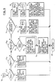
- the Redundant Primitive Logic described above could be implemented by hardwired logic having the structure shown in Figure 8.
- this Figure gives a schematic overview of logic for comparing corresponding true and false positions in a bitmap comprising eight bits only (ie. for three primitives). The bits of the bitmap are input to respective inputs 92 to 99.
- the hardwired logic shown in Figure 8 comprises three decoder blocks, 100, 101 and 102 for determining whether or not one or more of the primitives u, v and w redundant.
- Each decoder block compares the appropriate primitive true and primitive false bits in the bitmap for a respective one of the primitives.
- the selection of the appropriate bits is performed by hardwired connections 103 and the comparisons are performed by EXOR gates 104 in each of the decoder blocks.
- the outputs of the EXOR gates are ORed together by a network of OR gates 105 to form the output for the decoder block, respectively outputs 106, 107 and 108 for the decoder blocks 100, 101 and 102.
- a signal level "zero" at the output 106 of the decoder block 100 indicates that the corresponding primitive u is redundant.
- signal level "zero" outputs at the outputs 107 and 108 of the decoder blocks 101 and 102 indicate that the correspond ing primitives v and w, respectively are redundant. It will be apparent to the skilled person how to implement this logic for a bitmap for any given number of primitives given the teaching of this Figure and the preceding description. It will also be apparent to the skilled person that the logic shown in Figure 8 can be enhanced to provide the processing of a relmap as well.
- the separation of the logic into the separate blocks of Figure 3 is for ease of explanation only and that some or all of the blocks could be combined in other examples of a solid modelling system in accordance with the present invention.
- the operations performed in some of the blocks of logic may be performed instead or additionally in other of the blocks of logic.
- the simplification logic could be arranged to count the primitives remaining as it simplifies the structure, instead of, or in addition to, the counting of primitives performed in the primitive counting logic.
Landscapes
- Physics & Mathematics (AREA)
- Engineering & Computer Science (AREA)
- Computer Graphics (AREA)
- Geometry (AREA)
- Software Systems (AREA)
- General Physics & Mathematics (AREA)
- Theoretical Computer Science (AREA)
- Image Generation (AREA)
Applications Claiming Priority (2)
| Application Number | Priority Date | Filing Date | Title |
|---|---|---|---|
| GB8729630A GB2214037A (en) | 1987-12-18 | 1987-12-18 | Solid modelling system |
| GB8729630 | 1987-12-18 |
Publications (3)
| Publication Number | Publication Date |
|---|---|
| EP0321080A2 true EP0321080A2 (de) | 1989-06-21 |
| EP0321080A3 EP0321080A3 (de) | 1991-10-09 |
| EP0321080B1 EP0321080B1 (de) | 1994-06-01 |
Family
ID=10628738
Family Applications (1)
| Application Number | Title | Priority Date | Filing Date |
|---|---|---|---|
| EP88310188A Expired - Lifetime EP0321080B1 (de) | 1987-12-18 | 1988-10-28 | Modellierungssystem für Festkörper |
Country Status (5)
| Country | Link |
|---|---|
| US (1) | US5086495A (de) |
| EP (1) | EP0321080B1 (de) |
| JP (1) | JPH06101019B2 (de) |
| DE (1) | DE3889882T2 (de) |
| GB (1) | GB2214037A (de) |
Families Citing this family (39)
| Publication number | Priority date | Publication date | Assignee | Title |
|---|---|---|---|---|
| US5278983A (en) * | 1988-09-30 | 1994-01-11 | International Business Machines Corporation | Boundary representation solid modeling system |
| GB2231759B (en) * | 1989-05-18 | 1993-12-08 | Sun Microsystems Inc | Method and apparatus for the rendering of geometric volumes |
| US5113357A (en) * | 1989-05-18 | 1992-05-12 | Sun Microsystems, Inc. | Method and apparatus for rendering of geometric volumes |
| US5644689A (en) * | 1992-01-13 | 1997-07-01 | Hitachi, Ltd. | Arbitrary viewpoint three-dimensional imaging method using compressed voxel data constructed by a directed search of voxel data representing an image of an object and an arbitrary viewpoint |
| US5821940A (en) * | 1992-08-03 | 1998-10-13 | Ball Corporation | Computer graphics vertex index cache system for polygons |
| US5347459A (en) * | 1993-03-17 | 1994-09-13 | National Research Council Of Canada | Real time collision detection |
| US5563991A (en) * | 1993-11-24 | 1996-10-08 | Xerox Corporation | Using an image showing a perimeter relationship representation to obtain data indicating a relationship among distinctions |
| DE19528735A1 (de) * | 1994-08-06 | 1996-02-15 | Toyoda Automatic Loom Works | Motor zur Umwandlung der Drehung einer Welle in eine lineare Bewegung |
| US5692184A (en) * | 1995-05-09 | 1997-11-25 | Intergraph Corporation | Object relationship management system |
| US5760778A (en) * | 1995-08-15 | 1998-06-02 | Friedman; Glenn M. | Algorithm for representation of objects to enable robotic recongnition |
| US5883629A (en) * | 1996-06-28 | 1999-03-16 | International Business Machines Corporation | Recursive and anisotropic method and article of manufacture for generating a balanced computer representation of an object |
| NO306526B1 (no) * | 1997-12-30 | 1999-11-15 | Animagic Systems As | Fremgangsmaate for aa representere geometriske figurer og geometriske strukturer i datamaskinsystemer |
| US6618048B1 (en) | 1999-10-28 | 2003-09-09 | Nintendo Co., Ltd. | 3D graphics rendering system for performing Z value clamping in near-Z range to maximize scene resolution of visually important Z components |
| US20010047251A1 (en) * | 2000-03-03 | 2001-11-29 | Kemp William H. | CAD system which designs 3-D models |
| ATE467210T1 (de) * | 2000-04-07 | 2010-05-15 | Sony Dadc Austria Ag | Kopieverhinderungssytem für optische platten |
| US7119813B1 (en) | 2000-06-02 | 2006-10-10 | Nintendo Co., Ltd. | Variable bit field encoding |
| US6707458B1 (en) | 2000-08-23 | 2004-03-16 | Nintendo Co., Ltd. | Method and apparatus for texture tiling in a graphics system |
| US7002591B1 (en) | 2000-08-23 | 2006-02-21 | Nintendo Co., Ltd. | Method and apparatus for interleaved processing of direct and indirect texture coordinates in a graphics system |
| US6867781B1 (en) | 2000-08-23 | 2005-03-15 | Nintendo Co., Ltd. | Graphics pipeline token synchronization |
| US7034828B1 (en) | 2000-08-23 | 2006-04-25 | Nintendo Co., Ltd. | Recirculating shade tree blender for a graphics system |
| US6636214B1 (en) | 2000-08-23 | 2003-10-21 | Nintendo Co., Ltd. | Method and apparatus for dynamically reconfiguring the order of hidden surface processing based on rendering mode |
| US7538772B1 (en) | 2000-08-23 | 2009-05-26 | Nintendo Co., Ltd. | Graphics processing system with enhanced memory controller |
| US7061502B1 (en) | 2000-08-23 | 2006-06-13 | Nintendo Co., Ltd. | Method and apparatus for providing logical combination of N alpha operations within a graphics system |
| US7576748B2 (en) * | 2000-11-28 | 2009-08-18 | Nintendo Co. Ltd. | Graphics system with embedded frame butter having reconfigurable pixel formats |
| US6825851B1 (en) | 2000-08-23 | 2004-11-30 | Nintendo Co., Ltd. | Method and apparatus for environment-mapped bump-mapping in a graphics system |
| US7184059B1 (en) | 2000-08-23 | 2007-02-27 | Nintendo Co., Ltd. | Graphics system with copy out conversions between embedded frame buffer and main memory |
| US6700586B1 (en) | 2000-08-23 | 2004-03-02 | Nintendo Co., Ltd. | Low cost graphics with stitching processing hardware support for skeletal animation |
| US6811489B1 (en) | 2000-08-23 | 2004-11-02 | Nintendo Co., Ltd. | Controller interface for a graphics system |
| US6937245B1 (en) * | 2000-08-23 | 2005-08-30 | Nintendo Co., Ltd. | Graphics system with embedded frame buffer having reconfigurable pixel formats |
| US6980218B1 (en) * | 2000-08-23 | 2005-12-27 | Nintendo Co., Ltd. | Method and apparatus for efficient generation of texture coordinate displacements for implementing emboss-style bump mapping in a graphics rendering system |
| US7844842B2 (en) * | 2008-11-21 | 2010-11-30 | Apple Inc. | Variable refresh rate for power management |
| US8947444B1 (en) * | 2008-12-09 | 2015-02-03 | Nvidia Corporation | Distributed vertex attribute fetch |
| GB2497762B (en) * | 2011-12-20 | 2018-05-23 | Advanced Risc Mach Ltd | Intermediate value storage within a graphics processing apparatus |
| US10148499B2 (en) * | 2016-11-09 | 2018-12-04 | Seagate Technology Llc | Verifying distributed computing results via nodes configured according to a tree structure |
| JP2019128641A (ja) * | 2018-01-22 | 2019-08-01 | キヤノン株式会社 | 画像処理装置、画像処理方法及びプログラム |
| CN109522239A (zh) * | 2018-09-30 | 2019-03-26 | 上海恺英网络科技有限公司 | 一种共同特征数据确定的方法及设备 |
| US11321904B2 (en) | 2019-08-30 | 2022-05-03 | Maxon Computer Gmbh | Methods and systems for context passing between nodes in three-dimensional modeling |
| US11714928B2 (en) | 2020-02-27 | 2023-08-01 | Maxon Computer Gmbh | Systems and methods for a self-adjusting node workspace |
| US11373369B2 (en) * | 2020-09-02 | 2022-06-28 | Maxon Computer Gmbh | Systems and methods for extraction of mesh geometry from straight skeleton for beveled shapes |
Family Cites Families (7)
| Publication number | Priority date | Publication date | Assignee | Title |
|---|---|---|---|---|
| US4694404A (en) * | 1984-01-12 | 1987-09-15 | Key Bank N.A. | High-speed image generation of complex solid objects using octree encoding |
| US4649498A (en) * | 1984-05-08 | 1987-03-10 | The University Of Rochester | Computer systems for curve-solid classification and solid modeling |
| JPH0756678B2 (ja) * | 1985-11-01 | 1995-06-14 | 株式会社日立製作所 | 対話形形状モデリングシステム |
| US4809201A (en) * | 1985-12-02 | 1989-02-28 | Schlumberger Systems, Inc. | Graphic display region defining technique |
| US4862392A (en) * | 1986-03-07 | 1989-08-29 | Star Technologies, Inc. | Geometry processor for graphics display system |
| GB2194656B (en) * | 1986-09-03 | 1991-10-09 | Ibm | Method and system for solid modelling |
| US4816999A (en) * | 1987-05-20 | 1989-03-28 | International Business Machines Corporation | Method of detecting constants and removing redundant connections in a logic network |
-
1987
- 1987-12-18 GB GB8729630A patent/GB2214037A/en not_active Withdrawn
-
1988
- 1988-10-20 JP JP63263014A patent/JPH06101019B2/ja not_active Expired - Fee Related
- 1988-10-28 EP EP88310188A patent/EP0321080B1/de not_active Expired - Lifetime
- 1988-10-28 DE DE3889882T patent/DE3889882T2/de not_active Expired - Fee Related
- 1988-12-16 US US07/285,850 patent/US5086495A/en not_active Expired - Fee Related
Non-Patent Citations (4)
| Title |
|---|
| COMMUNICATIONS OF THE ACM, vol. 27, no. 7, July 1984, pages 684-694; R.B. TILOVE et al.: "A null-object detection algorithm for constructive solid geometry" * |
| COMPUTER GRAPHICS 80, August 1980, pages 335-343, Fareham, Hants, GB; J.R. WOODWARK et al.: "The derivation of graphics from volume models by recursive subdivision of the object space" * |
| COMPUTER-AIDED DESIGN, vol. 18, no. 6, July-August 1986, pages 307-315, London, GB; J.R. WOODWARK: "Generating wireframes from set-theoretic solid models by spatial division" * |
| PROCEEDINGS OF THE IEEE, vol. 73, no. 1, January 1985, pages 30-44, New York, US; A. REQUICHA et al.: "Boolean operations in solid modeling: Boundary evaluation and merging algorithms" * |
Also Published As
| Publication number | Publication date |
|---|---|
| DE3889882D1 (de) | 1994-07-07 |
| GB8729630D0 (en) | 1988-02-03 |
| EP0321080A3 (de) | 1991-10-09 |
| JPH06101019B2 (ja) | 1994-12-12 |
| JPH01169677A (ja) | 1989-07-04 |
| GB2214037A (en) | 1989-08-23 |
| EP0321080B1 (de) | 1994-06-01 |
| US5086495A (en) | 1992-02-04 |
| DE3889882T2 (de) | 1994-12-08 |
Similar Documents
| Publication | Publication Date | Title |
|---|---|---|
| EP0321080B1 (de) | Modellierungssystem für Festkörper | |
| EP0262304B1 (de) | Verfahren und System zur Festkörpermodellierung | |
| Laidlaw et al. | Constructive solid geometry for polyhedral objects | |
| Meagher | Geometric modeling using octree encoding | |
| US6862026B2 (en) | Process and device for collision detection of objects | |
| US4791583A (en) | Method for global blending of computer modeled solid objects using a convolution integral | |
| Hoffmann et al. | Towards implementing robust geometric computations | |
| Nirenstein et al. | Exact from-region visibility culling | |
| Akman et al. | Geometric computing and uniform grid technique | |
| Wang | Approximate boolean operations on large polyhedral solids with partial mesh reconstruction | |
| Miller | Analysis of quadric-surface-based solid models | |
| US8013854B2 (en) | Process for displaying objects of a PLM database and apparatus implementing this process | |
| Paoluzzi et al. | Boolean algebra over linear polyhedra | |
| US5222201A (en) | Method for displaying a portion of the body | |
| Neuhauser et al. | Interactive focus+ context rendering for hexahedral mesh inspection | |
| McMains | Geometric algorithms and data representation for solid freeform fabrication | |
| Forrest | A unified approach to geometric modelling | |
| Dıaz | Improvements in the ray tracing of implicit surfaces based on interval arithmetic | |
| Posdamer | Spatial sorting for sampled surface geometries | |
| Nehring‐Wirxel et al. | Exact and Efficient Mesh‐Kernel Generation | |
| GB2217958A (en) | Solid modelling | |
| Kercher | Generic implementation of CAD models for nuclear simulation | |
| CN119295639A (zh) | 一种基于异构算力加速的大场景消隐算法 | |
| Davis | Bounding Sphere Images: A Parametric Bounding Volume Hierarchy for Collision Detection on the GPU. | |
| JPS63178372A (ja) | 多面体形状作成装置 |
Legal Events
| Date | Code | Title | Description |
|---|---|---|---|
| PUAI | Public reference made under article 153(3) epc to a published international application that has entered the european phase |
Free format text: ORIGINAL CODE: 0009012 |
|
| AK | Designated contracting states |
Kind code of ref document: A2 Designated state(s): DE FR GB |
|
| 17P | Request for examination filed |
Effective date: 19891011 |
|
| PUAL | Search report despatched |
Free format text: ORIGINAL CODE: 0009013 |
|
| AK | Designated contracting states |
Kind code of ref document: A3 Designated state(s): DE FR GB |
|
| 17Q | First examination report despatched |
Effective date: 19930901 |
|
| GRAA | (expected) grant |
Free format text: ORIGINAL CODE: 0009210 |
|
| AK | Designated contracting states |
Kind code of ref document: B1 Designated state(s): DE FR GB |
|
| REF | Corresponds to: |
Ref document number: 3889882 Country of ref document: DE Date of ref document: 19940707 |
|
| ET | Fr: translation filed | ||
| PLBE | No opposition filed within time limit |
Free format text: ORIGINAL CODE: 0009261 |
|
| STAA | Information on the status of an ep patent application or granted ep patent |
Free format text: STATUS: NO OPPOSITION FILED WITHIN TIME LIMIT |
|
| 26N | No opposition filed | ||
| PGFP | Annual fee paid to national office [announced via postgrant information from national office to epo] |
Ref country code: FR Payment date: 19951009 Year of fee payment: 8 |
|
| PGFP | Annual fee paid to national office [announced via postgrant information from national office to epo] |
Ref country code: DE Payment date: 19951030 Year of fee payment: 8 |
|
| PG25 | Lapsed in a contracting state [announced via postgrant information from national office to epo] |
Ref country code: FR Effective date: 19970630 |
|
| PG25 | Lapsed in a contracting state [announced via postgrant information from national office to epo] |
Ref country code: DE Effective date: 19970701 |
|
| REG | Reference to a national code |
Ref country code: FR Ref legal event code: ST |
|
| PGFP | Annual fee paid to national office [announced via postgrant information from national office to epo] |
Ref country code: GB Payment date: 20001003 Year of fee payment: 13 |
|
| PG25 | Lapsed in a contracting state [announced via postgrant information from national office to epo] |
Ref country code: GB Free format text: LAPSE BECAUSE OF NON-PAYMENT OF DUE FEES Effective date: 20011028 |
|
| REG | Reference to a national code |
Ref country code: GB Ref legal event code: IF02 |
|
| GBPC | Gb: european patent ceased through non-payment of renewal fee |
Effective date: 20011028 |