EP0321078A2 - Hybrid suspension position and body velocity sensing system for automotive suspension control system - Google Patents
Hybrid suspension position and body velocity sensing system for automotive suspension control system Download PDFInfo
- Publication number
- EP0321078A2 EP0321078A2 EP88310071A EP88310071A EP0321078A2 EP 0321078 A2 EP0321078 A2 EP 0321078A2 EP 88310071 A EP88310071 A EP 88310071A EP 88310071 A EP88310071 A EP 88310071A EP 0321078 A2 EP0321078 A2 EP 0321078A2
- Authority
- EP
- European Patent Office
- Prior art keywords
- velocity
- suspension
- control system
- signal
- suspension unit
- Prior art date
- Legal status (The legal status is an assumption and is not a legal conclusion. Google has not performed a legal analysis and makes no representation as to the accuracy of the status listed.)
- Granted
Links
Images


Classifications
-
- B—PERFORMING OPERATIONS; TRANSPORTING
- B60—VEHICLES IN GENERAL
- B60G—VEHICLE SUSPENSION ARRANGEMENTS
- B60G17/00—Resilient suspensions having means for adjusting the spring or vibration-damper characteristics, for regulating the distance between a supporting surface and a sprung part of vehicle or for locking suspension during use to meet varying vehicular or surface conditions, e.g. due to speed or load
- B60G17/015—Resilient suspensions having means for adjusting the spring or vibration-damper characteristics, for regulating the distance between a supporting surface and a sprung part of vehicle or for locking suspension during use to meet varying vehicular or surface conditions, e.g. due to speed or load the regulating means comprising electric or electronic elements
- B60G17/016—Resilient suspensions having means for adjusting the spring or vibration-damper characteristics, for regulating the distance between a supporting surface and a sprung part of vehicle or for locking suspension during use to meet varying vehicular or surface conditions, e.g. due to speed or load the regulating means comprising electric or electronic elements characterised by their responsiveness, when the vehicle is travelling, to specific motion, a specific condition, or driver input
- B60G17/0165—Resilient suspensions having means for adjusting the spring or vibration-damper characteristics, for regulating the distance between a supporting surface and a sprung part of vehicle or for locking suspension during use to meet varying vehicular or surface conditions, e.g. due to speed or load the regulating means comprising electric or electronic elements characterised by their responsiveness, when the vehicle is travelling, to specific motion, a specific condition, or driver input to an external condition, e.g. rough road surface, side wind
-
- B—PERFORMING OPERATIONS; TRANSPORTING
- B60—VEHICLES IN GENERAL
- B60G—VEHICLE SUSPENSION ARRANGEMENTS
- B60G17/00—Resilient suspensions having means for adjusting the spring or vibration-damper characteristics, for regulating the distance between a supporting surface and a sprung part of vehicle or for locking suspension during use to meet varying vehicular or surface conditions, e.g. due to speed or load
- B60G17/015—Resilient suspensions having means for adjusting the spring or vibration-damper characteristics, for regulating the distance between a supporting surface and a sprung part of vehicle or for locking suspension during use to meet varying vehicular or surface conditions, e.g. due to speed or load the regulating means comprising electric or electronic elements
- B60G17/018—Resilient suspensions having means for adjusting the spring or vibration-damper characteristics, for regulating the distance between a supporting surface and a sprung part of vehicle or for locking suspension during use to meet varying vehicular or surface conditions, e.g. due to speed or load the regulating means comprising electric or electronic elements characterised by the use of a specific signal treatment or control method
-
- B—PERFORMING OPERATIONS; TRANSPORTING
- B60—VEHICLES IN GENERAL
- B60G—VEHICLE SUSPENSION ARRANGEMENTS
- B60G2400/00—Indexing codes relating to detected, measured or calculated conditions or factors
- B60G2400/20—Speed
- B60G2400/206—Body oscillation speed; Body vibration frequency
-
- B—PERFORMING OPERATIONS; TRANSPORTING
- B60—VEHICLES IN GENERAL
- B60G—VEHICLE SUSPENSION ARRANGEMENTS
- B60G2400/00—Indexing codes relating to detected, measured or calculated conditions or factors
- B60G2400/25—Stroke; Height; Displacement
- B60G2400/252—Stroke; Height; Displacement vertical
-
- B—PERFORMING OPERATIONS; TRANSPORTING
- B60—VEHICLES IN GENERAL
- B60G—VEHICLE SUSPENSION ARRANGEMENTS
- B60G2401/00—Indexing codes relating to the type of sensors based on the principle of their operation
- B60G2401/14—Photo or light sensitive means, e.g. Infrared
-
- B—PERFORMING OPERATIONS; TRANSPORTING
- B60—VEHICLES IN GENERAL
- B60G—VEHICLE SUSPENSION ARRANGEMENTS
- B60G2500/00—Indexing codes relating to the regulated action or device
- B60G2500/10—Damping action or damper
-
- B—PERFORMING OPERATIONS; TRANSPORTING
- B60—VEHICLES IN GENERAL
- B60G—VEHICLE SUSPENSION ARRANGEMENTS
- B60G2600/00—Indexing codes relating to particular elements, systems or processes used on suspension systems or suspension control systems
- B60G2600/14—Differentiating means, i.e. differential control
-
- B—PERFORMING OPERATIONS; TRANSPORTING
- B60—VEHICLES IN GENERAL
- B60G—VEHICLE SUSPENSION ARRANGEMENTS
- B60G2600/00—Indexing codes relating to particular elements, systems or processes used on suspension systems or suspension control systems
- B60G2600/18—Automatic control means
- B60G2600/184—Semi-Active control means
-
- B—PERFORMING OPERATIONS; TRANSPORTING
- B60—VEHICLES IN GENERAL
- B60G—VEHICLE SUSPENSION ARRANGEMENTS
- B60G2600/00—Indexing codes relating to particular elements, systems or processes used on suspension systems or suspension control systems
- B60G2600/22—Magnetic elements
- B60G2600/26—Electromagnets; Solenoids
-
- B—PERFORMING OPERATIONS; TRANSPORTING
- B60—VEHICLES IN GENERAL
- B60G—VEHICLE SUSPENSION ARRANGEMENTS
- B60G2800/00—Indexing codes relating to the type of movement or to the condition of the vehicle and to the end result to be achieved by the control action
- B60G2800/16—Running
- B60G2800/162—Reducing road induced vibrations
-
- B—PERFORMING OPERATIONS; TRANSPORTING
- B60—VEHICLES IN GENERAL
- B60G—VEHICLE SUSPENSION ARRANGEMENTS
- B60G2800/00—Indexing codes relating to the type of movement or to the condition of the vehicle and to the end result to be achieved by the control action
- B60G2800/90—System Controller type
- B60G2800/91—Suspension Control
- B60G2800/916—Body Vibration Control
Definitions
- This invention relates to a hybrid suspension position and body velocity sensor as well as to an associated automotive suspension control system.
- Automotive suspensions employing adjustable suspension units typically utilize one or more sensors for detecting the vertical position of a controlled road wheel and tire assembly with respect to either part of the suspension itself or another part of the chassis or body of the vehicle.
- the suspension position sensor indicates that the ride height is less than a prescribed low limit
- the adjustable suspension unit will be given the command to increase the ride height.
- the adjustable suspension unit will be given the command to lower, or decrease, the ride height.
- Vehicular height sensors are useful not only with ride height adjusting systems but also as transducers for use with adjustable suspension dampers. It is known for example to control suspension dampers based upon data concerning the speed of the suspension movement in jounce or rebound.
- U.S. Patent 4,625,993 illustrates another type of control system in which an accelerometer is used for the purpose of sensing body vertical velocity.
- U.S. Patent 4,065,154 describes a control system in which damping of an adjustable suspension unit is prescribed as a function of a pressure signal from the damper and the velocity of the wheel with respect to the body.
- a sensing system according to this invention may be used not only with adjustable suspension units capable of controlling vehicle ride height and suspension damping, but also with adjustable suspension units in which only suspension damping is variable.
- a system for generating a signal which is representative of the vertical velocity of the body of an automotive vehicle includes position sensor means for sensing the relative vertical position of a road wheel and tire assembly with respect to the body and for producing a suspension position signal corresponding to the road wheel and tire position.
- the system further includes processor means operatively associated with the position sensor means for integrating the position signal so as to produce a body velocity signal which is representative of the vertical velocity of the body.
- the position sensor may comprise a linear variable differential transformer or a Hall Effect device or yet other types of suitable sensing devices.
- the processor means may comprise a digital filter and preferably comprises a digital band pass filter.
- the processor means may further comprise means for differentiating the suspension position signal so as to obtain a suspension velocity signal and means for comparing the body velocity signal with the derived suspension velocity signal so that a control signal may be produced which has a value which is dependent upon the result of the comparison.
- an adjustment means for adjusting an adjustable suspension unit will respond to the control signal.
- an adjustable suspension unit will be adjusted to a position of maximum damping in the event that a comparison of body velocity and suspension velocity indicates that the motion of the body and the relative motion of the body with respect to the road wheel are in the same direction.
- the control system may include a body velocity threshold such that the control signal requiring adjustment of the suspension unit will be produced only in the event that the magnitude of the body velocity exceeds such threshold.
- the adjustable suspension unit may be adjusted to a position of minimum damping whenever the motion of the body and the relative motion of the body with respect to the road wheel are in opposite directions.
- a suspension position and body velocity sensing system is useful for practicing a number of suspension control algorithms in addition to those previously described. Accordingly, information from a system according to this invention is useful for adjusting the magnitude of the damping produced by the suspension unit so that the damping is proportional to the magnitude of the relative motion of the body with respect to a controlled road wheel. On the other hand, damping may be controlled so that the damping produced by the suspension unit is proportional to the magnitude of the body velocity.
- a system according to the present invention is useful in yet another control algorithm in which the adjustable suspension unit is adjusted to produce a high magnitude of damping force whenever body vertical velocity exceeds a first threshold value and (i) either the suspension velocity is less than a second threshold value, or (ii) the suspension unit was previously adjusted to produce a high magnitude of damping force.
- the adjustable suspension unit may be adjusted to the position of maximum damping in the event that the body velocity exceeds a threshold value.
- an adjustable suspension unit and suspension control system for a motor vehicle includes the previously described position sensor means for sensing the relative vertical position of a road wheel and tire assembly and processor means operatively associated with the sensor for generating signals representative of vertical body velocity and suspension velocity with respect to the body.
- the adjustable suspension unit may include adjustment means operatively connected with the processor means and responsive to control signals therefrom for adjusting the adjustable suspension unit.
- the adjustment means may comprise a valve housed within a piston attached to a piston rod within the suspension unit and electromagnetic means for receiving control signals from the processor and for operating the valve means.
- the valve may comprise a generally tubular sleeve having a coil wound about a portion of the sleeve.
- the coil will cooperate with a permanent magnet positioned in the suspension unit's piston such that an electromagnetic valve control force is produced when control signals from the processor are applied to the coil.
- the suspension position sensor may comprise a linear variable differential transformer or Hall Effect device or other suitable device. This system will function by comparing a body velocity signal with the suspension velocity signal obtained by differentiating the suspension position signal and by producing a control signal with a value which is dependent, on the result of the comparison.
- the present invention is related to the control of adjustable vehicular suspension units based upon at least the vertical velocity of a vehicle body.
- the present system dispenses with the troublesome accelerometers and instead utilizes the output of a sensor which would normally be operated for the purpose of disclosing the position of a road wheel with respect to the vehicle body, for the purpose of providing a signal from which vertical body velocity may be derived. It has been determined that body vertical velocity may be closely approximated by integrating the output of a position sensor which sensor detects the relative vertical position of a road wheel and tire assembly with respect to the body. This determination stems from the following considerations.
- B A Absolute body vertical acceleration
- B D Absolute body vertical displacement
- W D Absolute wheel vertical displacement
- K Spring rate
- B M Equivalent mass of vehicle body (one corner)
- Absolute body velocity and vertical direction is integral of absolute body acceleration:
- the signals of the suspension position sensor as well as the peripheral electronics connected with the sensor in the microprocessor typically exhibit DC offsets. These offsets must be filtered so as not to effect the vertical body velocity calculation. As a result, a pseudo-integrator or band pass filter is needed to attenuate the DC component of the suspension position sensor's signal. This band pass filter will further serve to integrate (low pass filter) frequencies above approximately 1 Hz. A gain vs. frequency plot is shown for such a filter in Figure 3. Frequencies at points a and b are chosen so as to result in an attenuation of about 3 decibels. In practice, points a and b are selected so that point a is slightly above 0.2 Hz, whereas point b is below above 0.2 Hz. Thus, the filter will cause DC offsets to be removed from the signal emanating from the position sensors 25 and 10 of Figures 2 and 7 respectively while at the same time integrating signals at frequencies above 1 Hz.
- Y(K) ⁇ (U(K) - U(K-2)) + ⁇ Y(K-1) - ⁇ Y(K-2)
- ⁇ , ⁇ , and ⁇ are constants that set the filter characteristics:
- T Sample period (6 ms)
- a Low pass cutoff frequency in radians
- b High pass cutoff frequency in radians
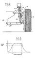
- FIG. 1 illustrates a vehicle equipped with a system according to the present invention.
- a road wheel and tire assembly 12 is subject to vertical motion controllable by suspension spring 16 and adjustable suspension unit 14.
- Each suspension also includes a suspension position sensor, 25, for sensing the relative vertical position of the road wheel and tire assembly with respect to the body or chassis of the vehicle.
- the position sensor produces a suspension position signal corresponding to the road wheel and tires' vertical position. Information from the position sensors is fed into control module 40.
- Figures 2 and 7 illustrate but two types of suspension systems suitable for use with the present invention.
- road wheel and tire assembly 12 is rotatably supported upon wheel carrier 13.
- lower control arm 18 is pivotally connected to the wheel carrier at its outboard end and to the body or chassis of the vehicle, 20, at its inboard end.
- an upper control arm and coil spring 16 complete the suspension geometry.
- Upper control arm 19 is pivotally attached at its outboard end to the wheel carrier and its inboard end to the chassis 20.
- the suspension shown in Figure 2 further includes adjustable suspension unit 14 which may have adjustable damping, or adjustable load carrying capabilities or both.
- Figure 2 further illustrates use of position sensor 25.
- This sensor may comprise a linear variable differential transformer (hereinafter "LVDT"), a Hall Effect device or one of a variety of other devices suitable for use according to the present invention. Regardless of the type of suspension position sensor chosen, the function of the sensor is to disclose the vertical position of the wheel and tire assembly as the wheel and tire moves through in the directions of jounce and rebound.
- LVDT linear variable differential transformer
- FIGS 5 and 6 illustrate the component parts and output characteristics of a typical LVDT.
- oscillator 30 drives an alternating current in primary winding 32.
- Two secondary windings, 36 are connected to a demodulator unit, 34.
- the coupling between the primary and secondary windings is dependent upon the position of slug 38.
- This slug which is comprised of a high permeability material, causes an imbalance in the coupling effect between the primary winding and the two secondary windings such that the difference between the output voltages of the secondary windings 36 is representative of the position of the slug.
- the direction of displacement of the slug affects the phase of the signal from the two secondary windings, which necessitates that the demodulator be sensitive to phase shifts.
- a typical output for an LVDT is illustrated in Figure 6, which shows that the voltage output of the LVDT is proportional to the displacement of slug 38.
- the raw sensor outputs will be passed through a signal conditioner comprising an amplifier with a second order low pass filter having a cutoff at 75 Hz. Such a filter is useful for making appropriate offsets to the output of the LVDT to result in a normalized sensor output voltage.
- a signal conditioner comprising an amplifier with a second order low pass filter having a cutoff at 75 Hz.
- Such a filter is useful for making appropriate offsets to the output of the LVDT to result in a normalized sensor output voltage.
- the suspension position sensor output will be further subjected to a differentiation to produce a control signal with a value corresponding to suspension vertical velocity.
- the differentiator may comprise an analog hardware filter or other type of analog or digital differentiating device known to those skilled in the art to which the present invention pertains.
- the microprocessor receives a signal corresponding to the position of the road wheel and tire assembly with respect to the body as well as a signal corresponding to the velocity of the road wheel and tire assembly with respect to the vehicle body, the microprocessor is free to begin performing calculations required for implementing various strategies according to the present invention.
- the microprocessor may be arranged according to a number of different architectures, but each would generally include an input-output control circuit (I/O) for exchanging data with external devices and a readable, addressable memory (RAM) for temporarily holding data while the data are being processed.
- I/O input-output control circuit
- RAM readable, addressable memory
- Control programs including unit commands will be sequentially read from a read-only memory (ROM).
- Unit commands will be executed by a central processing unit (CPU).
- a system will generate a signal which is representative of the vertical velocity of the body by first sensing the relative vertical position of the road wheel and tire assembly 12 by means of LVDT 25.
- the suspension position signal corresponding to the road wheel and tire position will be integrated within the microprocessor by means of the previously stated digital filter equation which will be loaded into the CPU.
- a vertical body velocity signal will be produced.
- the computer may then use a body velocity signal and suspension velocity signal obtained by differentiating the suspension position signal for producing a control signal with a value based upon a comparison of the two velocity signals-- i.e., the body velocity signal and the suspension velocity signal.
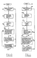
- Figure 10 illustrates an example of a first type of algorithm which may be practiced with a suspension Position and body velocity sensing system according to the present invention.
- computer transfers to block 92 wherein the output of the suspension position sensor is read.
- the suspension position sensor output is utilized according to the previously described differentiation method for calculating suspension vertical velocity.
- the suspension position signal is also utilized at block 96 for calculating body vertical velocity according to the previously described digital filtering method.
- the computer compares calculated body velocity and suspension velocity. In the event that each velocity is in the same direction, the computer will, at block 100, set the suspension unit to obtain maximum damping.
- the computer will, at block 102, set the suspension unit to the minimum damping Position. Thereafter, the algorithm returns to block 92 and continues with the same sequence of steps.
- the algorithm shown in Figure 10 may be modified so that the suspension unit is placed in a position so as to produce maximum damping only in the event that the magnitude of the body velocity exceeds a threshold value while at the same time the body velocity and suspension velocity are in the same direction. This will help to ensure that the adjustable suspension unit is not needlessly switched to a position of maximum damping when the body vertical velocity is at a small value.
- control signal output by the controller to the adjustable suspension unit may be selected such that the magnitude of the damping produced by the suspension unit is proportional to the magnitude of the relative motion of the body with respect to the road wheel.
- control signal may be selected such that the magnitude of the damping produced by the suspension unit is proportional to the magnitude of the body velocity alone, or alternatively, the signal may be proportional not only to the magnitude of the body velocity but also to the relative motion of the body with respect to the road wheel.
- a second control algorithm is shown in Figure 11. After reading suspension position and calculating suspension velocity and body velocity as before, the computer at block 112 compares body velocity to an appropriate threshold. If the body velocity exceeds such threshold, the computer, at block 114, asks alternative questions regarding the suspension velocity and the adjustment position of the suspension unit. The first question inquires as to the value of the suspension velocity, vis-a-vis an appropriate threshold value. The second question asks whether the suspension unit was previously adjusted for a high rate of damping during the immediately preceding loop through the algorithm. In the event that either question is answered positively, the computer will adjust the suspension unit at block 116 to a position of high damping. As before, the actual level of damping selected by the computer may be a variable function depending upon the prior velocity of the vehicle or the body or suspension velocities.
- a third algorithm for controlling a suspension by utilizing a system according to the present invention is shown in Figure 12.
- the computer After reading the suspension position and calculating body velocity at blocks 120 and 122 respectively, the computer compares the body velocity of block 124 to an appropriate threshold value. In the event that the body velocity exceeds such threshold the suspension will be adjusted to the position of maximum damping. Note that the algorithm at Figure 12 does not utilize suspension velocity as a control variable. Notwithstanding this difference between the algorithm shown at Figure 12 and those illustrated in Figures 10 and 11, it has been determined that for certain vehicles, an acceptable ride control is achieved without using suspension velocity as an input to the control algorithm.
- Figure 7 illustrates an alternative suspension which may be controlled by a system according to the present invention.
- an adjustable suspension unit, 14, is employed for producing damping within the suspension system.
- the suspension shown in Figure 7 is also capable, however, of controlling the height of the vehicle by means of height adjuster 22 which may, for example, comprise an air or hydropneumatic or other type of known ride height adjusting device.
- the embodiment of Figure 7 also includes a rotary height sensor 10 which may be configured using Hall Effect switches. This sensor utilizes link 26 and crank arm 24 for the purpose of converting the up and down motion of suspension control arm 18 into a rotary motion which may be input into the sensor.
- a typical waveform output for the two detectors included within sensor 10 as shown in Figure 8. Sensor 10 is described in detail in U.S.
- the output waveforms in Figure 8 indicate that the suspension's adjustable ride height can be divided up into a trim region labeled I and low and high regions adjoining the trim region. Each of the low and high regions has a separate marker region, labeled I and III respectively, which may be used by the control module to sense that the vehicle's ride height has moved a certain distance from the trim region in either the high or low direction.
- the outputs of detectors A and B shown in Figure 8 could be assigned values as follows.
- the trim region could be assigned a value of 0, whereas the region lying between those regions labeled I and II could be assigned a value of +1. Region II could be assigned a value of +2. Going in the "high" direction of Figure 8, the region lying between Regions I and III could be assigned a value of -1, whereas Region III could be assigned a value of -2.
- the computer may produce an integrated signal representative of a body vertical velocity. Such a signal is shown in Figure 13.
- Figure 13 is a plot of suspension position, actual body vertical velocity, and calculated body vertical velocity, all as functions of time. Although the product of a simulation, these plots agree with experimental data which show that a digital filtering technique according to the present invention produces a calculated body vertical velocity signal which has generally good agreement with actual body vertical velocity as sensed by an accelerometer.
- Figure 13 shows that if the suspension is subjected to a rather sharp input at time A, the body velocity will almost immediately show a marked change. This change results from acceleration of the body as a consequence of the imposition of force by the suspension into the body. As the suspension damper absorbs the spring and inertial forces at work upon the body, the actual body velocity gradually subsides according to a sinusoidal function.
- a digital filter according to the present invention simulates this sinusoidal decaying velocity by means of an exponential decay as shown in Figure 13. It is interesting to note that the magnitude of the disagreement between the actual and calculated body velocity signals is not great. The difference, if any, becomes of little consequence in algorithms which rely only upon the absolute value of either suspension velocity or body velocity or both.
- Figure 9 illustrates a portion of a shock absorber useful for practicing the algorithms of the present invention which direct adjustable damping unit 14 to either maximum or minimum damping positions.
- a piston assembly slidably housed within pressure cylinder 48 as attached to piston rod 50.
- the piston rod itself is hollow and provides a reservoir for fluid in conjunction with yet another externally mounted reservoir (not shown).
- the upper end of the piston rod is attached to the body or chassis of the vehicle whereas the lower end of pressure cylinder 48 is attached to the suspension. This is generally shown in Figures 2 and 7.
- the piston assembly is sealably engaged with the inner wall of pressure cylinder 48 by means of sealing band 52 which is affixed about the outer periphery of the piston at its lowermost extremity.
- the piston contains a plurality of valve mechanisms.
- Rebound valve disc 54 is mounted to the lower face of the piston and maintained in contact with that face by means of rebound valve spring 56.
- the rebound valve disc has a port 58 which comprises a leakage path for fluid past the rebound disc even when this disc is in the closed position.
- the function of the rebound disc is to assist in the control of fluid when a shock absorber or strut including the illustrated piston is moving in the rebound direction i.e., in a direction tending to extend the length of the shock absorber.
- Jounce valve disc 60 is mounted in an intermediate portion of the piston and, as its name implies, assists in the control of fluid flow during jounce movement of the piston i.e., movement in a direction tending to contract the overall length of the shock absorber or strut.
- the jounce valve is maintained in contact with its seat by means of jounce valve spring 62.
- This disc has one or more jounce valve ports 64 formed in its midsection so as to permit flow of fluid into an annular recess formed in the jounce valve seating surface.
- the shock absorber illustrated in Figure 9 is capable of producing high and low levels of damping in both jounce and rebound directions because of sleeve valve 66, which comprises a tubular sleeve having a coil 70 wound about a portion thereof with the coil being positioned in proximity to a permanent magnet, 72, in this case a neodymium magnet.
- the sleeve valve is biased in the open direction i.e., in a direction tending to define an open port, 69, by means of sleeve valve spring 68.
- shock absorber is merely representative of a class of devices capable of achieving high levels of force output with very low response times.
- a system according to the present invention could be employed not only with the illustrated parallel arm and MacPherson strut suspensions but with other types such as the Hotchkiss or quadralink designs.
- a system according to the present invention may be used in connection with active suspension systems as well.
Landscapes
- Engineering & Computer Science (AREA)
- Mechanical Engineering (AREA)
- Vehicle Body Suspensions (AREA)
Abstract
Description
- This invention relates to a hybrid suspension position and body velocity sensor as well as to an associated automotive suspension control system.
- Automotive suspensions employing adjustable suspension units typically utilize one or more sensors for detecting the vertical position of a controlled road wheel and tire assembly with respect to either part of the suspension itself or another part of the chassis or body of the vehicle. In the case of vehicles using load leveling or air or hydropneumatic suspension systems, it is necessary to know the ride height of the vehicle in order to determine whether correction of the ride height is required. If the suspension position sensor indicates that the ride height is less than a prescribed low limit, the adjustable suspension unit will be given the command to increase the ride height. Conversely, in the event that sensed ride height exceeds a prescribed high limit, the adjustable suspension unit will be given the command to lower, or decrease, the ride height.
- Vehicular height sensors are useful not only with ride height adjusting systems but also as transducers for use with adjustable suspension dampers. It is known for example to control suspension dampers based upon data concerning the speed of the suspension movement in jounce or rebound.
- Certain other suspension control algorithms utilize information concerning the vertical velocity of the vehicle's body. U.S. Patents 3,807,678 and 4,696,489 disclose control systems in which accelerometers are employed for the purpose of sensing the vertical velocity of a vehicle body. A second sensor is employed with each of the systems of the '678 and '489 patents for determining the vertical velocity of the suspension and wheel and tire assembly with respect to the body of the vehicle. These two vertical velocities are compared and then as a result of such comparison a damping setting is chosen for an adjustable suspension unit. It should be noted that in each of the systems of the '678 and '489 patents a separate accelerometer is required to provide a signal which may be integrated to provide a signal representative of body vertical velocity. The body vertical velocity signal is then used, as previously described, in a control algorithm for operating the adjustable suspension units.
- U.S. Patent 4,625,993 illustrates another type of control system in which an accelerometer is used for the purpose of sensing body vertical velocity.
- U.S. Patent 4,065,154 describes a control system in which damping of an adjustable suspension unit is prescribed as a function of a pressure signal from the damper and the velocity of the wheel with respect to the body.
- It is an object of the present invention to provide a hybrid suspension position and body velocity sensing system for an automotive suspension control system requiring only a single sensing element for not only suspension position but also body vertical velocity information. It is an advantage of the present invention that a sensing system according to this invention obviates the need for accelerometer for the purpose of generating signals representative of body vertical velocity.
- It is an advantage of the present invention that a sensing system according to this invention may be used not only with adjustable suspension units capable of controlling vehicle ride height and suspension damping, but also with adjustable suspension units in which only suspension damping is variable.
- According to the present invention, a system for generating a signal which is representative of the vertical velocity of the body of an automotive vehicle includes position sensor means for sensing the relative vertical position of a road wheel and tire assembly with respect to the body and for producing a suspension position signal corresponding to the road wheel and tire position. The system further includes processor means operatively associated with the position sensor means for integrating the position signal so as to produce a body velocity signal which is representative of the vertical velocity of the body. The position sensor may comprise a linear variable differential transformer or a Hall Effect device or yet other types of suitable sensing devices. The processor means may comprise a digital filter and preferably comprises a digital band pass filter.
- The processor means may further comprise means for differentiating the suspension position signal so as to obtain a suspension velocity signal and means for comparing the body velocity signal with the derived suspension velocity signal so that a control signal may be produced which has a value which is dependent upon the result of the comparison. In practice, an adjustment means for adjusting an adjustable suspension unit will respond to the control signal.
- In one control strategy according to the present invention, an adjustable suspension unit will be adjusted to a position of maximum damping in the event that a comparison of body velocity and suspension velocity indicates that the motion of the body and the relative motion of the body with respect to the road wheel are in the same direction. To avoid undue corrections of the suspension unit, the control system may include a body velocity threshold such that the control signal requiring adjustment of the suspension unit will be produced only in the event that the magnitude of the body velocity exceeds such threshold. In order to provide an acceptable ride characteristic using a system in which an adjustable suspension unit is adjusted to a position of maximum damping in the event that the comparison of the body velocity and suspension velocity indicates that the motion of the body and relative motion of the body with respect to the road wheel are in the same direction, the adjustable suspension unit may be adjusted to a position of minimum damping whenever the motion of the body and the relative motion of the body with respect to the road wheel are in opposite directions.
- A suspension position and body velocity sensing system according to the present invention is useful for practicing a number of suspension control algorithms in addition to those previously described. Accordingly, information from a system according to this invention is useful for adjusting the magnitude of the damping produced by the suspension unit so that the damping is proportional to the magnitude of the relative motion of the body with respect to a controlled road wheel. On the other hand, damping may be controlled so that the damping produced by the suspension unit is proportional to the magnitude of the body velocity. A system according to the present invention is useful in yet another control algorithm in which the adjustable suspension unit is adjusted to produce a high magnitude of damping force whenever body vertical velocity exceeds a first threshold value and (i) either the suspension velocity is less than a second threshold value, or (ii) the suspension unit was previously adjusted to produce a high magnitude of damping force. In yet another control algorithm, the adjustable suspension unit may be adjusted to the position of maximum damping in the event that the body velocity exceeds a threshold value.
- According to this invention, an adjustable suspension unit and suspension control system for a motor vehicle includes the previously described position sensor means for sensing the relative vertical position of a road wheel and tire assembly and processor means operatively associated with the sensor for generating signals representative of vertical body velocity and suspension velocity with respect to the body. The adjustable suspension unit may include adjustment means operatively connected with the processor means and responsive to control signals therefrom for adjusting the adjustable suspension unit. The adjustment means may comprise a valve housed within a piston attached to a piston rod within the suspension unit and electromagnetic means for receiving control signals from the processor and for operating the valve means. The valve may comprise a generally tubular sleeve having a coil wound about a portion of the sleeve. It is intended that the coil will cooperate with a permanent magnet positioned in the suspension unit's piston such that an electromagnetic valve control force is produced when control signals from the processor are applied to the coil. As before, the suspension position sensor may comprise a linear variable differential transformer or Hall Effect device or other suitable device. This system will function by comparing a body velocity signal with the suspension velocity signal obtained by differentiating the suspension position signal and by producing a control signal with a value which is dependent, on the result of the comparison.
- The invention will now be described further by way of example, with reference to the accompanying drawings, in which:
- Figure 1 is a partially schematic representation of a vehicle equipped with a system according to the present invention.
- Figure 2 is a frontal elevation of a front suspension portion of the vehicle shown in Figure 1.
- Figure 3 is a response characteristic plot for a digital filter according to the present invention.
- Figure 4 is a block diagram illustrating several of the component parts of a control system according to the present invention.
- Figure 5 is a partially schematic representation of a linear variable differential transformer.
- Figure 6 illustrates the output waveform of the linear variable differential transformer illustrated in Figure 5.
- Figure 7 is a frontal elevation of a vehicular suspension according to the present invention showing a rotary type of height sensor mechanism.
- Figure 8 illustrates an example of an output waveform from a height sensor according to Figure 7.
- Figure 9 is a sectional view of a shock absorber piston useful for practicing the present invention.
- Figures 10, 11 and 12 illustrate various suspension control algorithms which may be practiced with the system according to the present invention.
- Figure 13 illustrates the output data received from a system according to the present invention in terms of suspension position and calculated body velocity. This figure also includes a comparison of calculated body vertical velocity with actual body vertical velocity.
- As noted above, the present invention is related to the control of adjustable vehicular suspension units based upon at least the vertical velocity of a vehicle body. Also, as previously noted, the present system dispenses with the troublesome accelerometers and instead utilizes the output of a sensor which would normally be operated for the purpose of disclosing the position of a road wheel with respect to the vehicle body, for the purpose of providing a signal from which vertical body velocity may be derived. It has been determined that body vertical velocity may be closely approximated by integrating the output of a position sensor which sensor detects the relative vertical position of a road wheel and tire assembly with respect to the body. This determination stems from the following considerations.
- Vertical body acceleration for each individual road wheel and tire suspension may be modeled according to the following equation:

BA = Absolute body vertical acceleration
BD = Absolute body vertical displacement
WD = Absolute wheel vertical displacement
K = Spring rate
BM = Equivalent mass of vehicle body (one corner)
FS = Damping force developed by shock absorber
(BD-WD) = Measured shock absorber displacement - Absolute body velocity and vertical direction is integral of absolute body acceleration:

- It has been determined that for many vehicles the natural frequency of the body is in the range of 1 to 2 Hz while the natural frequency of the road wheel and tire assembly and associated suspension is 10-13 Hz. It has further been determined that the 2 Hz component of body acceleration and, therefore, the body velocity, is due primarily to spring force. The force of the suspension springs contributes approximately 75% of the 2 Hz component of body acceleration. As a result, by measuring road wheel displacement and neglecting the small contribution of shock absorber force (FS/BM), absolute body velocity is approximated by the following equation:
BV ≈ [-(K/BM)*(BD-WD)] - Reviewing the last equation set forth above, one notices that the value of one of the two terms within the parenthesis is fixed, i.e., K/BM, whereas the value of the other two terms within the parenthesis, i.e., BD - WD is simply equal to the sensed reading from a suspension position sensor which senses the relative vertical position of a road wheel and tire assembly with respect to the body of the vehicle. Accordingly, by integrating the suspension position sensor output and multiplying the result by constant, a good approximation can be obtained of the body's vertical velocity. The integration required herein may easily be performed by means of a digital filter contained within a microprocessor. Such digital filtering requires the following considerations. First, the signals of the suspension position sensor as well as the peripheral electronics connected with the sensor in the microprocessor typically exhibit DC offsets. These offsets must be filtered so as not to effect the vertical body velocity calculation. As a result, a pseudo-integrator or band pass filter is needed to attenuate the DC component of the suspension position sensor's signal. This band pass filter will further serve to integrate (low pass filter) frequencies above approximately 1 Hz. A gain vs. frequency plot is shown for such a filter in Figure 3. Frequencies at points a and b are chosen so as to result in an attenuation of about 3 decibels. In practice, points a and b are selected so that point a is slightly above 0.2 Hz, whereas point b is below above 0.2 Hz. Thus, the filter will cause DC offsets to be removed from the signal emanating from the
position sensors - The following format has been found to be useful for implementing the previously described digital filter.
Y(K) = α(U(K) - U(K-2)) +βY(K-1) - γY(K-2)
where:
Y(K) is estimated body velocity at time t=K
Y(K-1) is estimated body velocity at time t=K-1
Y(K-2) is estimated body velocity at time t=K-2
U(K) is suspension unit displacement at time t=K
U(K-1) is suspension unit displacement at time t=K-1
U(K-2) is suspension unit displacement at time t=K-2
In the equation above, α, β, and γ are constants that set the filter characteristics:
T = Sample period (6 ms)
a = Low pass cutoff frequency in radians
b = High pass cutoff frequency in radians - Figure 1 illustrates a vehicle equipped with a system according to the present invention. In each corner of the vehicle, a road wheel and tire assembly, 12, is subject to vertical motion controllable by
suspension spring 16 andadjustable suspension unit 14. Each suspension also includes a suspension position sensor, 25, for sensing the relative vertical position of the road wheel and tire assembly with respect to the body or chassis of the vehicle. The position sensor produces a suspension position signal corresponding to the road wheel and tires' vertical position. Information from the position sensors is fed intocontrol module 40. - Figures 2 and 7 illustrate but two types of suspension systems suitable for use with the present invention. As shown in each of these figures, road wheel and
tire assembly 12 is rotatably supported uponwheel carrier 13. In each case,lower control arm 18 is pivotally connected to the wheel carrier at its outboard end and to the body or chassis of the vehicle, 20, at its inboard end. In Figure 2, an upper control arm andcoil spring 16 complete the suspension geometry.Upper control arm 19 is pivotally attached at its outboard end to the wheel carrier and its inboard end to thechassis 20. The suspension shown in Figure 2 further includesadjustable suspension unit 14 which may have adjustable damping, or adjustable load carrying capabilities or both. Figure 2 further illustrates use ofposition sensor 25. This sensor may comprise a linear variable differential transformer (hereinafter "LVDT"), a Hall Effect device or one of a variety of other devices suitable for use according to the present invention. Regardless of the type of suspension position sensor chosen, the function of the sensor is to disclose the vertical position of the wheel and tire assembly as the wheel and tire moves through in the directions of jounce and rebound. - Figures 5 and 6 illustrate the component parts and output characteristics of a typical LVDT. In practice,
oscillator 30 drives an alternating current in primary winding 32. Two secondary windings, 36, are connected to a demodulator unit, 34. The coupling between the primary and secondary windings is dependent upon the position ofslug 38. This slug, which is comprised of a high permeability material, causes an imbalance in the coupling effect between the primary winding and the two secondary windings such that the difference between the output voltages of thesecondary windings 36 is representative of the position of the slug. The direction of displacement of the slug affects the phase of the signal from the two secondary windings, which necessitates that the demodulator be sensitive to phase shifts. A typical output for an LVDT is illustrated in Figure 6, which shows that the voltage output of the LVDT is proportional to the displacement ofslug 38. - Mounting of
LVDT 25 in a position as shown in Figure 2, such that the slug moves into and out of the core area of the LVDT as the suspension moves in jounce and rebound will thus produce a signal which is proportional to the position of the sensor, and hence, the suspension and wheel and tire assembly. As shown in Figure 4, the output of eachsensor 25 is fed intocontrol module 40. - It has been determined that an Intel model 8096 microprocessor and a Trans-Tek series 240 LVDT are useful for practicing the present invention. Before passing into the microprocessor, the raw sensor outputs will be passed through a signal conditioner comprising an amplifier with a second order low pass filter having a cutoff at 75 Hz. Such a filter is useful for making appropriate offsets to the output of the LVDT to result in a normalized sensor output voltage. Before passing into the microprocessor the suspension position sensor output will be further subjected to a differentiation to produce a control signal with a value corresponding to suspension vertical velocity. The differentiator may comprise an analog hardware filter or other type of analog or digital differentiating device known to those skilled in the art to which the present invention pertains.
- Once the microprocessor receives a signal corresponding to the position of the road wheel and tire assembly with respect to the body as well as a signal corresponding to the velocity of the road wheel and tire assembly with respect to the vehicle body, the microprocessor is free to begin performing calculations required for implementing various strategies according to the present invention.
- The microprocessor may be arranged according to a number of different architectures, but each would generally include an input-output control circuit (I/O) for exchanging data with external devices and a readable, addressable memory (RAM) for temporarily holding data while the data are being processed. Control programs including unit commands will be sequentially read from a read-only memory (ROM). Unit commands will be executed by a central processing unit (CPU).
- A system according to this invention will generate a signal which is representative of the vertical velocity of the body by first sensing the relative vertical position of the road wheel and
tire assembly 12 by means ofLVDT 25. The suspension position signal corresponding to the road wheel and tire position will be integrated within the microprocessor by means of the previously stated digital filter equation which will be loaded into the CPU. As a result of the integration of the position signal, a vertical body velocity signal will be produced. The computer may then use a body velocity signal and suspension velocity signal obtained by differentiating the suspension position signal for producing a control signal with a value based upon a comparison of the two velocity signals-- i.e., the body velocity signal and the suspension velocity signal. - Figure 10 illustrates an example of a first type of algorithm which may be practiced with a suspension Position and body velocity sensing system according to the present invention. After starting at
block 90, computer transfers to block 92 wherein the output of the suspension position sensor is read. Atblock 94, the suspension position sensor output is utilized according to the previously described differentiation method for calculating suspension vertical velocity. The suspension position signal is also utilized atblock 96 for calculating body vertical velocity according to the previously described digital filtering method. At block 98, the computer compares calculated body velocity and suspension velocity. In the event that each velocity is in the same direction, the computer will, at block 100, set the suspension unit to obtain maximum damping. If, however, the body velocity and suspension velocity are not in the same direction, the computer will, atblock 102, set the suspension unit to the minimum damping Position. Thereafter, the algorithm returns to block 92 and continues with the same sequence of steps. The algorithm shown in Figure 10 may be modified so that the suspension unit is placed in a position so as to produce maximum damping only in the event that the magnitude of the body velocity exceeds a threshold value while at the same time the body velocity and suspension velocity are in the same direction. This will help to ensure that the adjustable suspension unit is not needlessly switched to a position of maximum damping when the body vertical velocity is at a small value. - It is possible to implement the algorithm shown in Figure 10 by means of an adjustable suspension unit having continuously adjustable damping characteristics rather than merely maximum or minimum settings. If this mode of implementation is chosen, the control signal output by the controller to the adjustable suspension unit may be selected such that the magnitude of the damping produced by the suspension unit is proportional to the magnitude of the relative motion of the body with respect to the road wheel. Similarly, the control signal may be selected such that the magnitude of the damping produced by the suspension unit is proportional to the magnitude of the body velocity alone, or alternatively, the signal may be proportional not only to the magnitude of the body velocity but also to the relative motion of the body with respect to the road wheel.
- A second control algorithm according to the present invention is shown in Figure 11. After reading suspension position and calculating suspension velocity and body velocity as before, the computer at block 112 compares body velocity to an appropriate threshold. If the body velocity exceeds such threshold, the computer, at block 114, asks alternative questions regarding the suspension velocity and the adjustment position of the suspension unit. The first question inquires as to the value of the suspension velocity, vis-a-vis an appropriate threshold value. The second question asks whether the suspension unit was previously adjusted for a high rate of damping during the immediately preceding loop through the algorithm. In the event that either question is answered positively, the computer will adjust the suspension unit at block 116 to a position of high damping. As before, the actual level of damping selected by the computer may be a variable function depending upon the prior velocity of the vehicle or the body or suspension velocities.
- A third algorithm for controlling a suspension by utilizing a system according to the present invention is shown in Figure 12. After reading the suspension position and calculating body velocity at
blocks block 124 to an appropriate threshold value. In the event that the body velocity exceeds such threshold the suspension will be adjusted to the position of maximum damping. Note that the algorithm at Figure 12 does not utilize suspension velocity as a control variable. Notwithstanding this difference between the algorithm shown at Figure 12 and those illustrated in Figures 10 and 11, it has been determined that for certain vehicles, an acceptable ride control is achieved without using suspension velocity as an input to the control algorithm. - As noted above, Figure 7 illustrates an alternative suspension which may be controlled by a system according to the present invention. As before, an adjustable suspension unit, 14, is employed for producing damping within the suspension system. The suspension shown in Figure 7 is also capable, however, of controlling the height of the vehicle by means of
height adjuster 22 which may, for example, comprise an air or hydropneumatic or other type of known ride height adjusting device. The embodiment of Figure 7 also includes arotary height sensor 10 which may be configured using Hall Effect switches. This sensor utilizeslink 26 and crankarm 24 for the purpose of converting the up and down motion ofsuspension control arm 18 into a rotary motion which may be input into the sensor. A typical waveform output for the two detectors included withinsensor 10 as shown in Figure 8.Sensor 10 is described in detail in U.S. Patent Application , filed on , which is assigned to assignee of the present invention, and which is hereby incorporated by reference herein. In general, the output waveforms in Figure 8 indicate that the suspension's adjustable ride height can be divided up into a trim region labeled I and low and high regions adjoining the trim region. Each of the low and high regions has a separate marker region, labeled I and III respectively, which may be used by the control module to sense that the vehicle's ride height has moved a certain distance from the trim region in either the high or low direction. For the purpose of providing input to the digital filter described herein, the outputs of detectors A and B shown in Figure 8 could be assigned values as follows. As an example, the trim region could be assigned a value of 0, whereas the region lying between those regions labeled I and II could be assigned a value of +1. Region II could be assigned a value of +2. Going in the "high" direction of Figure 8, the region lying between Regions I and III could be assigned a value of -1, whereas Region III could be assigned a value of -2. In this manner the computer may produce an integrated signal representative of a body vertical velocity. Such a signal is shown in Figure 13. - Figure 13 is a plot of suspension position, actual body vertical velocity, and calculated body vertical velocity, all as functions of time. Although the product of a simulation, these plots agree with experimental data which show that a digital filtering technique according to the present invention produces a calculated body vertical velocity signal which has generally good agreement with actual body vertical velocity as sensed by an accelerometer. Figure 13 shows that if the suspension is subjected to a rather sharp input at time A, the body velocity will almost immediately show a marked change. This change results from acceleration of the body as a consequence of the imposition of force by the suspension into the body. As the suspension damper absorbs the spring and inertial forces at work upon the body, the actual body velocity gradually subsides according to a sinusoidal function. A digital filter according to the present invention simulates this sinusoidal decaying velocity by means of an exponential decay as shown in Figure 13. It is interesting to note that the magnitude of the disagreement between the actual and calculated body velocity signals is not great. The difference, if any, becomes of little consequence in algorithms which rely only upon the absolute value of either suspension velocity or body velocity or both.
- Figure 9 illustrates a portion of a shock absorber useful for practicing the algorithms of the present invention which direct adjustable damping
unit 14 to either maximum or minimum damping positions. In conventional fashion, a piston assembly slidably housed withinpressure cylinder 48 as attached topiston rod 50. The piston rod itself is hollow and provides a reservoir for fluid in conjunction with yet another externally mounted reservoir (not shown). In further conventional fashion, the upper end of the piston rod is attached to the body or chassis of the vehicle whereas the lower end ofpressure cylinder 48 is attached to the suspension. This is generally shown in Figures 2 and 7. The piston assembly is sealably engaged with the inner wall ofpressure cylinder 48 by means of sealingband 52 which is affixed about the outer periphery of the piston at its lowermost extremity. The piston contains a plurality of valve mechanisms. Reboundvalve disc 54 is mounted to the lower face of the piston and maintained in contact with that face by means of rebound valve spring 56. The rebound valve disc has aport 58 which comprises a leakage path for fluid past the rebound disc even when this disc is in the closed position. As its name implies, the function of the rebound disc is to assist in the control of fluid when a shock absorber or strut including the illustrated piston is moving in the rebound direction i.e., in a direction tending to extend the length of the shock absorber.Jounce valve disc 60 is mounted in an intermediate portion of the piston and, as its name implies, assists in the control of fluid flow during jounce movement of the piston i.e., movement in a direction tending to contract the overall length of the shock absorber or strut. The jounce valve is maintained in contact with its seat by means ofjounce valve spring 62. This disc has one or morejounce valve ports 64 formed in its midsection so as to permit flow of fluid into an annular recess formed in the jounce valve seating surface. - The shock absorber illustrated in Figure 9 is capable of producing high and low levels of damping in both jounce and rebound directions because of
sleeve valve 66, which comprises a tubular sleeve having acoil 70 wound about a portion thereof with the coil being positioned in proximity to a permanent magnet, 72, in this case a neodymium magnet. The sleeve valve is biased in the open direction i.e., in a direction tending to define an open port, 69, by means ofsleeve valve spring 68. When a control signal is applied tocoil 70 by means ofcoil connector 74 andcontrol lead 76, the coil and permanent magnet will combine to produce a force tending to closesleeve valve 66 againstsleeve valve seat 67, thereby preventing flow past the sleeve valve. When the sleeve valve is in the closed position, both jounce and rebound flow are prevented from passing through the port defined by the sleeve valve andsleeve valve seat 67. Accordingly, jounce flow passing overjounce valve disc 60 must pass through pop-off channel 82 andpast ball valve 78 which is maintained against its seat by means ofball valve spring 80. After passingball valve 78 the flow passes into the interior of the piston rod and is then sent to an externally mounted reservoir. During closed sleeve valve operation in the rebound condition, fluid trapped above the piston byjounce valve disc 60 will first pass through pop-off channel 82 and then downpast rebound disc 54. When the sleeve valve is open, and when the piston is moving in the rebound direction, fluid trapped above the piston will pass through the sleeve valve port defined by the sleeve valve and sleeve valve seat and then overrebound disc 54. Because the fluid pressure in this case will not be allowed to build, no fluid will flow through pop-off channel 82past ball valve 78. Similarly, during jounce movement when the sleeve valve is in the open position, fluid will flow pastjounce valve disc 60 and through the port defined by the sleeve valve and its seat. Again, no fluid will flow through the pop-off channel because fluid pressure will not be allowed to build to any appreciable degree within the shock absorber. Those skilled in the art will appreciate in view of this disclosure that the illustrated shock absorber is merely representative of a class of devices capable of achieving high levels of force output with very low response times. Those skilled in the art should further realize in view of this disclosure that a system according to the present invention could be employed not only with the illustrated parallel arm and MacPherson strut suspensions but with other types such as the Hotchkiss or quadralink designs. A system according to the present invention may be used in connection with active suspension systems as well. These and all other variations which basically rely upon the teachings by which this disclosure has advanced the art are properly considered within the scope of this invention as defined by the appended claims.
Claims (15)
Applications Claiming Priority (2)
| Application Number | Priority Date | Filing Date | Title |
|---|---|---|---|
| US07/133,098 US4838574A (en) | 1987-12-14 | 1987-12-14 | Hybrid suspension position and body velocity sensing system for automotive suspension control system |
| US133098 | 1998-08-12 |
Publications (3)
| Publication Number | Publication Date |
|---|---|
| EP0321078A2 true EP0321078A2 (en) | 1989-06-21 |
| EP0321078A3 EP0321078A3 (en) | 1990-06-06 |
| EP0321078B1 EP0321078B1 (en) | 1993-06-09 |
Family
ID=22456995
Family Applications (1)
| Application Number | Title | Priority Date | Filing Date |
|---|---|---|---|
| EP88310071A Expired - Lifetime EP0321078B1 (en) | 1987-12-14 | 1988-10-26 | Hybrid suspension position and body velocity sensing system for automotive suspension control system |
Country Status (4)
| Country | Link |
|---|---|
| US (1) | US4838574A (en) |
| EP (1) | EP0321078B1 (en) |
| CA (1) | CA1324646C (en) |
| DE (1) | DE3881663T2 (en) |
Cited By (7)
| Publication number | Priority date | Publication date | Assignee | Title |
|---|---|---|---|---|
| WO1991000187A1 (en) * | 1989-06-29 | 1991-01-10 | Robert Bosch Gmbh | Semi-active regulation of chassis |
| EP0426339A1 (en) * | 1989-11-02 | 1991-05-08 | General Motors Corporation | Vehicle suspension apparatus |
| DE4039629A1 (en) * | 1990-12-12 | 1992-06-17 | Bosch Gmbh Robert | SYSTEM FOR GENERATING SIGNALS FOR CONTROLLING OR CONTROLLING A CONTROLLABLE OR REGULATABLE CHASSIS |
| EP0512608A2 (en) * | 1991-05-06 | 1992-11-11 | General Motors Corporation | Suspension controller |
| GB2256026A (en) * | 1991-05-17 | 1992-11-25 | Atsugi Unisia Corp | Control for shock absorber |
| DE4126731A1 (en) * | 1991-08-13 | 1993-02-18 | Teves Gmbh Alfred | Semi-active suspension for vehicle - has filter to produce bandwidth of relevant frequencies and has displacement sensors on each wheel support |
| WO2007079733A3 (en) * | 2006-01-10 | 2007-08-30 | Zahnradfabrik Friedrichshafen | Method for determining at least one displacement state of a vehicle body |
Families Citing this family (33)
| Publication number | Priority date | Publication date | Assignee | Title |
|---|---|---|---|---|
| DE3738284A1 (en) * | 1986-12-09 | 1988-06-30 | Bosch Gmbh Robert | DEVICE FOR ACTIVE CHASSIS CONTROL IN MOTOR VEHICLES |
| US5358305A (en) * | 1987-08-13 | 1994-10-25 | Nissan Motor Co., Ltd. | Suspension system for automotive vehicle or the like |
| DE3821609A1 (en) * | 1988-06-27 | 1989-12-28 | Bayerische Motoren Werke Ag | CONTROL DEVICE FOR STABILIZING A VEHICLE |
| DE3838845A1 (en) * | 1988-11-17 | 1990-05-23 | Bergische Stahlindustrie | SPATIAL SINGLE WHEEL SUSPENSION FOR WHEELS OF RAIL VEHICLES |
| JP3080257B2 (en) * | 1991-08-06 | 2000-08-21 | 株式会社ユニシアジェックス | Vehicle suspension system |
| US5267466A (en) * | 1991-09-26 | 1993-12-07 | Ford Motor Co. | Apparatus and method for calibrating a suspension control module |
| JPH0648133A (en) * | 1991-10-03 | 1994-02-22 | Unisia Jecs Corp | Suspension device for vehicle |
| DE4133237C2 (en) * | 1991-10-05 | 2001-10-11 | Bosch Gmbh Robert | Suspension control system |
| US5396973A (en) * | 1991-11-15 | 1995-03-14 | Lord Corporation | Variable shock absorber with integrated controller, actuator and sensors |
| DE4243979C2 (en) * | 1991-12-26 | 1998-10-01 | Atsugi Unisia Corp | Control device for setting the damping characteristic of a vehicle suspension |
| JPH0699718A (en) * | 1992-09-18 | 1994-04-12 | Nippondenso Co Ltd | Damping force-changeable shock absorber control device |
| US6259982B1 (en) | 1993-02-02 | 2001-07-10 | Trw Inc. | Method and apparatus for controlling an active suspension system |
| GB2287769B (en) * | 1994-03-21 | 1998-04-29 | Monroe Auto Equipment Co | Automatic damper system |
| WO1997030858A2 (en) * | 1996-02-26 | 1997-08-28 | Board Of Regents, The University Of Texas System | Constant force suspension, near constant force suspension, and associated control algorithms |
| US6129364A (en) * | 1996-04-26 | 2000-10-10 | Fisher; Kenneth G. | Independent suspensions |
| JP3152185B2 (en) * | 1997-11-18 | 2001-04-03 | 株式会社豊田自動織機製作所 | Axle swing angle detection device for industrial vehicle and industrial vehicle |
| WO2000027659A1 (en) * | 1998-11-11 | 2000-05-18 | Kenmar Company Trust | Enhanced computer optimized adaptive air spring suspension |
| DE10221718A1 (en) | 2002-05-16 | 2003-11-27 | Bayerische Motoren Werke Ag | Motor vehicle, in particular passenger cars, with a roll stabilization device |
| US7645916B2 (en) * | 2003-01-23 | 2010-01-12 | Specialty Silicone Fabricators, Inc. | Elastically deformable fabric with gel coated surface |
| US6941822B2 (en) | 2003-06-10 | 2005-09-13 | Visteon Global Technologies, Inc. | Angular displacement sensing system and method using brushless DC motor commutation hall effect sensors |
| US7842428B2 (en) * | 2004-05-28 | 2010-11-30 | Idatech, Llc | Consumption-based fuel cell monitoring and control |
| JP4229208B1 (en) * | 2007-10-31 | 2009-02-25 | トヨタ自動車株式会社 | Mounting angle measuring device and mounting angle measuring method |
| DE102009008994A1 (en) | 2009-02-14 | 2010-08-19 | Bayerische Motoren Werke Aktiengesellschaft | Method for regulating damping force of infinitely variable semi-active damper between body and chassis of motor vehicle, involves utilizing relative speed of damper piston rod for damper pipe as reference variable |
| US8918253B2 (en) | 2012-06-25 | 2014-12-23 | Ford Global Technologies, Llc | Ride performance optimization in an active suspension system |
| US9738132B2 (en) | 2012-06-25 | 2017-08-22 | Ford Global Technologies, Llc | Ride performance optimization in an active suspension system |
| US9101519B2 (en) | 2013-02-07 | 2015-08-11 | Dallas Smith Corporation | Leveling ramp for a wheelchair |
| DE102014011162B4 (en) * | 2014-07-25 | 2017-12-21 | Audi Ag | Method for operating an active chassis |
| JP6278995B2 (en) * | 2016-03-16 | 2018-02-14 | 本田技研工業株式会社 | Electromagnetic damper system |
| US10252594B2 (en) | 2016-10-21 | 2019-04-09 | Ford Global Technologies, Llc | Extensions and performance improvements for non-contact ride height sensing |
| US10532624B2 (en) * | 2017-03-06 | 2020-01-14 | Ford Global Technologies, Llc | Methods and apparatus to calibrate height sensors of a vehicle suspension |
| JP6939660B2 (en) * | 2018-03-13 | 2021-09-22 | トヨタ自動車株式会社 | Vehicle driving control system |
| US11274940B2 (en) | 2018-06-08 | 2022-03-15 | Koepke InnoTek Ltd. T/A Motoklik | Suspension position monitoring system |
| US11951792B2 (en) * | 2020-02-24 | 2024-04-09 | Ford Global Technologies, Llc | Suspension component damage detection with marker |
Citations (6)
| Publication number | Priority date | Publication date | Assignee | Title |
|---|---|---|---|---|
| EP0027869A2 (en) * | 1979-10-27 | 1981-05-06 | Messerschmitt-Bölkow-Blohm Gesellschaft mit beschränkter Haftung | Shock and vibration damping arrangement for vehicles |
| EP0127094A2 (en) * | 1983-05-20 | 1984-12-05 | Kabushiki Kaisha Toyota Chuo Kenkyusho | Active suspension apparatus |
| EP0139145A1 (en) * | 1983-08-24 | 1985-05-02 | Mitsubishi Denki Kabushiki Kaisha | Suspension device for automobiles |
| EP0221486A2 (en) * | 1985-10-26 | 1987-05-13 | Toyota Jidosha Kabushiki Kaisha | Shock absorber controller |
| EP0222329A2 (en) * | 1985-11-07 | 1987-05-20 | Kabushiki Kaisha Toyota Chuo Kenkyusho | Vibration control apparatus |
| US4696489A (en) * | 1985-01-14 | 1987-09-29 | Nissan Motor Company, Limited | Automotive suspension system with variable damping characteristics |
Family Cites Families (6)
| Publication number | Priority date | Publication date | Assignee | Title |
|---|---|---|---|---|
| US3807678A (en) * | 1972-09-19 | 1974-04-30 | Lord Corp | System for controlling the transmission of energy between spaced members |
| GB1555124A (en) * | 1975-06-07 | 1979-11-07 | Lucas Industries Ltd | Vehicle suspension systems |
| US4468050A (en) * | 1983-08-15 | 1984-08-28 | Woods Lonnie K | Computer optimized adaptive suspension system |
| WO1984002886A1 (en) * | 1983-01-21 | 1984-08-02 | Lotus Car | Vehicle suspension system |
| DE8336759U1 (en) * | 1983-04-11 | 1985-11-28 | F & O Electronic Systems GmbH & Co, 6901 Neckarsteinach | Shock absorbers with adjustable damping characteristics |
| JPS61178212A (en) * | 1985-02-04 | 1986-08-09 | Nippon Denso Co Ltd | Car level control device |
-
1987
- 1987-12-14 US US07/133,098 patent/US4838574A/en not_active Expired - Lifetime
-
1988
- 1988-10-14 CA CA000580172A patent/CA1324646C/en not_active Expired - Fee Related
- 1988-10-26 EP EP88310071A patent/EP0321078B1/en not_active Expired - Lifetime
- 1988-10-26 DE DE88310071T patent/DE3881663T2/en not_active Expired - Fee Related
Patent Citations (6)
| Publication number | Priority date | Publication date | Assignee | Title |
|---|---|---|---|---|
| EP0027869A2 (en) * | 1979-10-27 | 1981-05-06 | Messerschmitt-Bölkow-Blohm Gesellschaft mit beschränkter Haftung | Shock and vibration damping arrangement for vehicles |
| EP0127094A2 (en) * | 1983-05-20 | 1984-12-05 | Kabushiki Kaisha Toyota Chuo Kenkyusho | Active suspension apparatus |
| EP0139145A1 (en) * | 1983-08-24 | 1985-05-02 | Mitsubishi Denki Kabushiki Kaisha | Suspension device for automobiles |
| US4696489A (en) * | 1985-01-14 | 1987-09-29 | Nissan Motor Company, Limited | Automotive suspension system with variable damping characteristics |
| EP0221486A2 (en) * | 1985-10-26 | 1987-05-13 | Toyota Jidosha Kabushiki Kaisha | Shock absorber controller |
| EP0222329A2 (en) * | 1985-11-07 | 1987-05-20 | Kabushiki Kaisha Toyota Chuo Kenkyusho | Vibration control apparatus |
Cited By (12)
| Publication number | Priority date | Publication date | Assignee | Title |
|---|---|---|---|---|
| WO1991000187A1 (en) * | 1989-06-29 | 1991-01-10 | Robert Bosch Gmbh | Semi-active regulation of chassis |
| EP0426339A1 (en) * | 1989-11-02 | 1991-05-08 | General Motors Corporation | Vehicle suspension apparatus |
| DE4039629A1 (en) * | 1990-12-12 | 1992-06-17 | Bosch Gmbh Robert | SYSTEM FOR GENERATING SIGNALS FOR CONTROLLING OR CONTROLLING A CONTROLLABLE OR REGULATABLE CHASSIS |
| EP0512608A2 (en) * | 1991-05-06 | 1992-11-11 | General Motors Corporation | Suspension controller |
| EP0512608A3 (en) * | 1991-05-06 | 1994-05-11 | Gen Motors Corp | Suspension controller |
| GB2256026A (en) * | 1991-05-17 | 1992-11-25 | Atsugi Unisia Corp | Control for shock absorber |
| GB2256026B (en) * | 1991-05-17 | 1995-02-01 | Atsugi Unisia Corp | Control for shock absorber |
| US5429384A (en) * | 1991-05-17 | 1995-07-04 | Atsugi Unisia Corporation | Control for shock absorber |
| DE4126731A1 (en) * | 1991-08-13 | 1993-02-18 | Teves Gmbh Alfred | Semi-active suspension for vehicle - has filter to produce bandwidth of relevant frequencies and has displacement sensors on each wheel support |
| DE4126731C2 (en) * | 1991-08-13 | 2001-03-01 | Continental Teves Ag & Co Ohg | Chassis control system for motor vehicles |
| WO2007079733A3 (en) * | 2006-01-10 | 2007-08-30 | Zahnradfabrik Friedrichshafen | Method for determining at least one displacement state of a vehicle body |
| US8428807B2 (en) | 2006-01-10 | 2013-04-23 | Zf Friedrichshafen Ag | Method for determining at least one displacement state of a vehicle body |
Also Published As
| Publication number | Publication date |
|---|---|
| EP0321078A3 (en) | 1990-06-06 |
| DE3881663D1 (en) | 1993-07-15 |
| CA1324646C (en) | 1993-11-23 |
| EP0321078B1 (en) | 1993-06-09 |
| US4838574A (en) | 1989-06-13 |
| DE3881663T2 (en) | 1993-10-07 |
Similar Documents
| Publication | Publication Date | Title |
|---|---|---|
| US4838574A (en) | Hybrid suspension position and body velocity sensing system for automotive suspension control system | |
| US4826205A (en) | Anti-squat control system for automotive suspension system | |
| US5071157A (en) | Full vehicle suspension control | |
| US5377107A (en) | System and method for controlling damping force characteristic of shock absorber applicable to automotive suspension | |
| US6397134B1 (en) | Vehicle suspension control with enhanced body control in steering crossover | |
| EP0246772B1 (en) | A suspension system for a motor vehicle | |
| EP0219866B1 (en) | System for vehicle body roll control with overshoot prevention | |
| US5016908A (en) | Method and apparatus for controlling shock absorbers | |
| KR0169183B1 (en) | Apparatus and method for controlling damping force characteristic of suspension system | |
| US6219602B1 (en) | Vehicle suspension control with stability in turn enhancement | |
| EP0239831B1 (en) | Suspension control method and apparatus | |
| EP0769396A3 (en) | Automotive vehicle suspension control apparatus | |
| US5740039A (en) | Vehicle wheel suspension arrangements | |
| EP0752331A2 (en) | Automotive vehicle suspension control system | |
| JPS63251318A (en) | Suspension control system adaptive to running condition of automobile | |
| US5054813A (en) | Rolling suppressive control system for automotive suspension system with enhanced response characteristics | |
| US5979885A (en) | Damping coefficient control apparatus for damping mechanism in vehicle suspension system | |
| US5365432A (en) | System and method for optimally controlling damping force characteristics of front and rear suspension units of four-wheeled vehicle | |
| US6097999A (en) | Vehicle suspension control system and method | |
| EP0446637B1 (en) | Apparatus for controlling damping force of shock absorber | |
| GB2297952A (en) | Suspension control system for vehicle shock absorbers | |
| US6019495A (en) | Apparatus for detecting step-out of suspension control system | |
| EP0411193B1 (en) | Damping force control system for shock absorbers | |
| US5481459A (en) | Control system for an active suspension system in a motor vehicle and method for controlling motor vehicle handling around curves | |
| US5142477A (en) | Suspension control system |
Legal Events
| Date | Code | Title | Description |
|---|---|---|---|
| PUAI | Public reference made under article 153(3) epc to a published international application that has entered the european phase |
Free format text: ORIGINAL CODE: 0009012 |
|
| AK | Designated contracting states |
Kind code of ref document: A2 Designated state(s): DE FR GB IT |
|
| PUAL | Search report despatched |
Free format text: ORIGINAL CODE: 0009013 |
|
| AK | Designated contracting states |
Kind code of ref document: A3 Designated state(s): DE FR GB IT |
|
| 17P | Request for examination filed |
Effective date: 19901027 |
|
| 17Q | First examination report despatched |
Effective date: 19920203 |
|
| GRAA | (expected) grant |
Free format text: ORIGINAL CODE: 0009210 |
|
| AK | Designated contracting states |
Kind code of ref document: B1 Designated state(s): DE FR GB IT |
|
| PG25 | Lapsed in a contracting state [announced via postgrant information from national office to epo] |
Ref country code: IT Free format text: LAPSE BECAUSE OF FAILURE TO SUBMIT A TRANSLATION OF THE DESCRIPTION OR TO PAY THE FEE WITHIN THE PRESCRIBED TIME-LIMIT;WARNING: LAPSES OF ITALIAN PATENTS WITH EFFECTIVE DATE BEFORE 2007 MAY HAVE OCCURRED AT ANY TIME BEFORE 2007. THE CORRECT EFFECTIVE DATE MAY BE DIFFERENT FROM THE ONE RECORDED. Effective date: 19930609 |
|
| ET | Fr: translation filed | ||
| REF | Corresponds to: |
Ref document number: 3881663 Country of ref document: DE Date of ref document: 19930715 |
|
| REG | Reference to a national code |
Ref country code: GB Ref legal event code: 746 Effective date: 19930928 |
|
| PLBE | No opposition filed within time limit |
Free format text: ORIGINAL CODE: 0009261 |
|
| STAA | Information on the status of an ep patent application or granted ep patent |
Free format text: STATUS: NO OPPOSITION FILED WITHIN TIME LIMIT |
|
| REG | Reference to a national code |
Ref country code: FR Ref legal event code: DL |
|
| 26N | No opposition filed | ||
| REG | Reference to a national code |
Ref country code: FR Ref legal event code: CD Ref country code: FR Ref legal event code: TP |
|
| REG | Reference to a national code |
Ref country code: GB Ref legal event code: IF02 |
|
| PGFP | Annual fee paid to national office [announced via postgrant information from national office to epo] |
Ref country code: FR Payment date: 20021009 Year of fee payment: 15 |
|
| PG25 | Lapsed in a contracting state [announced via postgrant information from national office to epo] |
Ref country code: FR Free format text: LAPSE BECAUSE OF NON-PAYMENT OF DUE FEES Effective date: 20040630 |
|
| REG | Reference to a national code |
Ref country code: FR Ref legal event code: ST |
|
| PGFP | Annual fee paid to national office [announced via postgrant information from national office to epo] |
Ref country code: DE Payment date: 20051014 Year of fee payment: 18 |
|
| PGFP | Annual fee paid to national office [announced via postgrant information from national office to epo] |
Ref country code: GB Payment date: 20051017 Year of fee payment: 18 |
|
| PG25 | Lapsed in a contracting state [announced via postgrant information from national office to epo] |
Ref country code: DE Free format text: LAPSE BECAUSE OF NON-PAYMENT OF DUE FEES Effective date: 20070501 |
|
| GBPC | Gb: european patent ceased through non-payment of renewal fee |
Effective date: 20061026 |
|
| PG25 | Lapsed in a contracting state [announced via postgrant information from national office to epo] |
Ref country code: GB Free format text: LAPSE BECAUSE OF NON-PAYMENT OF DUE FEES Effective date: 20061026 |