EP0321024B1 - Interchangeable and insertable ink ribbon cassette for a printer - Google Patents
Interchangeable and insertable ink ribbon cassette for a printer Download PDFInfo
- Publication number
- EP0321024B1 EP0321024B1 EP88202790A EP88202790A EP0321024B1 EP 0321024 B1 EP0321024 B1 EP 0321024B1 EP 88202790 A EP88202790 A EP 88202790A EP 88202790 A EP88202790 A EP 88202790A EP 0321024 B1 EP0321024 B1 EP 0321024B1
- Authority
- EP
- European Patent Office
- Prior art keywords
- printer
- cassette
- ink ribbon
- contact
- electric motor
- Prior art date
- Legal status (The legal status is an assumption and is not a legal conclusion. Google has not performed a legal analysis and makes no representation as to the accuracy of the status listed.)
- Expired - Lifetime
Links
- 230000008878 coupling Effects 0.000 claims description 2
- 238000010168 coupling process Methods 0.000 claims description 2
- 238000005859 coupling reaction Methods 0.000 claims description 2
- 238000003780 insertion Methods 0.000 claims description 2
- 230000037431 insertion Effects 0.000 claims description 2
- 230000013011 mating Effects 0.000 description 2
- 230000008439 repair process Effects 0.000 description 2
- 230000007547 defect Effects 0.000 description 1
- 230000002950 deficient Effects 0.000 description 1
- 238000006073 displacement reaction Methods 0.000 description 1
- 230000007257 malfunction Effects 0.000 description 1
Images
Classifications
-
- B—PERFORMING OPERATIONS; TRANSPORTING
- B41—PRINTING; LINING MACHINES; TYPEWRITERS; STAMPS
- B41J—TYPEWRITERS; SELECTIVE PRINTING MECHANISMS, i.e. MECHANISMS PRINTING OTHERWISE THAN FROM A FORME; CORRECTION OF TYPOGRAPHICAL ERRORS
- B41J32/00—Ink-ribbon cartridges
- B41J32/02—Ink-ribbon cartridges for endless ribbons
Definitions
- the invention relates to a printer with an exchangeably insertable ink ribbon cassette, which has a storage space for an ink ribbon and a transport device for the ink ribbon which can be driven by an electric motor via a reduction gear.
- the invention has for its object to design the arrangement of the type mentioned in such a way that the susceptibility to repairs of the printer is reduced.
- the solution is achieved in that the electric motor and the reduction gear are arranged in a drive housing which is firmly integrated into the housing of the ink ribbon cassette and in that means are provided for establishing a power connection from the motor to the printer by means of a detachable contact connection.
- the electric motor and its reduction gear are no longer part of the printer but of the cassette. In the event of a defect in these components, only the then defective cassette needs to be replaced by an operator, the help of a skilled technician being no longer required.
- the effort for a drive assigned to a cassette is considerably less than when assigned to the printer, because it only has to be dimensioned for the relatively short life of a cassette.
- the initial cost of a printer including a cartridge is reduced.
- the ribbon cassette according to the invention must be electrically connected to a printer. This is possible in a simple manner in that the contact connection through the Cassette arranged connector takes place, which are inserted into associated mating connectors of the printer when the cassette is inserted into the printer.
- the electrical connection can be made automatically without additional effort in that resiliently excellent contact elements, which are electrically connected to the electric motor, are provided from a cassette wall, which contact the associated mating contact surfaces of the printer with the cassette inserted in a current-conducting manner.
- the contact elements of the cassette are advantageously arranged in a plane parallel to their direction of insertion.
- the corresponding electrical contact surfaces can slide to a certain extent relative to one another, so that tolerance differences in the cassette position may be permitted without impairing the power connections.
- the contact surfaces of the cassette are arranged in a plane orthogonal to the pivot axis in the vicinity of the pivot axis. A displacement of the contact connection within particularly narrow limits is sufficient.
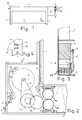
- FIG. 1 a section of an ink ribbon 3 runs in the area between side arms 1 and 2, a large length of which is stored in a storage space 4.
- the ink ribbon 3 is moved further in the direction of the arrow 5 by means of a drive which is provided in the integrated drive housing 6.
- FIGS 2 to 4 show details of a drive designed according to the invention for a ribbon cassette.
- a motor 12 operated with a DC voltage of less than 12 volts drives its belt wheel 13 via the toothed belt 14 the gears 15 and 16 of a reduction gear.
- the gearwheel 16 meshes with the transport roller 23, during the rotation of which the ink ribbon 3 clamped between the transport rollers 23 and 24 is pulled.
- the gears 15 and 16 can advantageously be molded onto the bottom wall of the drive housing 6.
- the connecting lines 17 and 18 coming from the electric motor 12 are connected to sliding contacts 19 and 20 which protrude from spring arms 21 and 22 of a contact carrier 25.
- the sliding contacts 19 and 20 are arranged in the immediate vicinity of the axis of rotation 11, so that their sliding movement when pivoting the ribbon cassette is as small as possible.
Landscapes
- Impression-Transfer Materials And Handling Thereof (AREA)
Description
Die Erfindung bezieht sich auf einen Drucker mit einer austauschbar einlegbaren Farbbandkassette, welche einen Speicherraum für ein Farbband und eine über ein Untersetzungsgetriebe durch einen Elektromotor antreibbare Transporteinrichtung für das Farbband aufweist.The invention relates to a printer with an exchangeably insertable ink ribbon cassette, which has a storage space for an ink ribbon and a transport device for the ink ribbon which can be driven by an electric motor via a reduction gear.
Bei einer bekannten Kassette dieser Art (EP-A 01 58 963) werden die Transporteinrichtungen über eine beim Einlegen der Kassette in Eingriff gebrachte Kupplung mit dem Untersetzungsgetriebe eines im Drucker angeordneten Elektromotors gekuppelt. Untersetzungsgetriebe und Motor müssen dauerfest für die gesamte Lebensdauer des Druckers ausgelegt sein. Dennoch sind Störungen auch dieser Baugruppen des Druckers nicht ausschließbar und müssen gegebenenfalls von einem fachkundigen Techniker behoben werden.In a known cassette of this type (EP-A 01 58 963), the transport devices are coupled to the reduction gear of an electric motor arranged in the printer via a coupling engaged when the cassette is inserted. Reduction gear and motor must be designed to be durable for the entire life of the printer. Nevertheless, malfunctions of these components of the printer cannot be excluded and may have to be remedied by a competent technician.
Der Erfindung liegt die Aufgabe zugrunde, die Anordnung der eingangs genannten Art derart zu gestalten, daß die Reparaturanfälligkeit des Druckers verringert wird.The invention has for its object to design the arrangement of the type mentioned in such a way that the susceptibility to repairs of the printer is reduced.
Die Lösung gelingt dadurch, daß der Elektromotor und das Untersetzungsgetriebe in einem an das Gehäuse der Farbbandkassette fest integrierten Antriebsgehäuse angeordnet und daß Mittel zur Herstellung einer Stromverbindung vom Motor zum Drucker mittels einer lösbaren Kontaktverbindung vorgesehen sind.The solution is achieved in that the electric motor and the reduction gear are arranged in a drive housing which is firmly integrated into the housing of the ink ribbon cassette and in that means are provided for establishing a power connection from the motor to the printer by means of a detachable contact connection.
Erfindungsgemäß sind der Elektromotor und sein Untersetzungsgetriebe nicht mehr Bestandteile des Druckers sondern der Kassette. Bei einem Fehler dieser Bauelemente braucht lediglich die dann defekte Kassette von einer Bedienungsperson ausgewechselt zu werden, wobei die Hilfe eines fachkundigen Technikers nicht mehr erforderlich ist.According to the invention, the electric motor and its reduction gear are no longer part of the printer but of the cassette. In the event of a defect in these components, only the then defective cassette needs to be replaced by an operator, the help of a skilled technician being no longer required.
Der Aufwand für einen einer Kassette zugeordneten Antrieb ist erheblich geringer als bei Zuordnung zum Drucker, weil er lediglich für die relativ geringe Lebensdauer einer Kassette dimensioniert werden muß. Die Anfangskosten für einen Drucker einschließlich einer Kassette sind verringert.The effort for a drive assigned to a cassette is considerably less than when assigned to the printer, because it only has to be dimensioned for the relatively short life of a cassette. The initial cost of a printer including a cartridge is reduced.
Zwar sind die Kosten für eine erfindungsgemäß mit eigenem Antrieb versehene Austauschkassette geringfügig höher, doch bedeutet das auch nach häufiger Verwendung von Austauschkassetten keinen Nachteil, weil die Ersparnis infolge verringerter Reparaturkosten schwerer wiegt.Although the costs for an exchange cassette provided with its own drive according to the invention are slightly higher, this does not mean a disadvantage even after frequent replacement cassette use, because the savings due to reduced repair costs outweigh the costs.
Die erfindungsgemäße Farbbandkassette muß elektrisch mit einem Drucker verbunden werden. Das ist auf einfache Weise dadurch möglich, daß die Kontaktverbindung durch an der Kassette angeordnete Stecker erfolgt, welche bei in den Drucker eingelegter Kassette in zugeordnete Gegen-Steckkupplungen des Druckers eingeführt sind.The ribbon cassette according to the invention must be electrically connected to a printer. This is possible in a simple manner in that the contact connection through the Cassette arranged connector takes place, which are inserted into associated mating connectors of the printer when the cassette is inserted into the printer.
Die elektrische Verbindung kann ohne zusätzlichen Aufwand automatisch dadurch erfolgen, daß aus einer Kassettenwandung federnd hervorragende, mit dem Elektromotor elektrisch verbundene Kontaktelemente vorgesehen sind, welche zugeordnete Gegenkontaktflächen des Druckers bei eingelegter Kassette stromleitend berühren.The electrical connection can be made automatically without additional effort in that resiliently excellent contact elements, which are electrically connected to the electric motor, are provided from a cassette wall, which contact the associated mating contact surfaces of the printer with the cassette inserted in a current-conducting manner.
Die Kontaktelemente der Kassette sind vorteilhaft in einer zu ihrer Einlegerichtung parallelen Ebene angeordnet. Dabei können die korrespondierenden elektrischen Kontaktflächen relativ zueinander in gewissem Ausmaß gleiten, so daß gegebenenfalls Toleranzunterschiede der Kassettenlage ohne Beeinträchtigung der Stromverbindungen zulässig sind.The contact elements of the cassette are advantageously arranged in a plane parallel to their direction of insertion. The corresponding electrical contact surfaces can slide to a certain extent relative to one another, so that tolerance differences in the cassette position may be permitted without impairing the power connections.
Bevorzugt ist bei einer um eine zum Drucker raumfeste Schwenkachse schwenkbar gehalterten Kassette vorgesehen, daß die Kontaktflächen der Kassette in einer zur Schwenkachse orthogonalen Ebene in Nähe der Schwenkachse angeordnet sind. Dabei genügt eine Verschiebbarkeit der Kontaktverbindung in besonders engen Grenzen.In the case of a cassette which is pivotally mounted about a pivot axis which is fixed to the printer, it is preferably provided that the contact surfaces of the cassette are arranged in a plane orthogonal to the pivot axis in the vicinity of the pivot axis. A displacement of the contact connection within particularly narrow limits is sufficient.
Die Erfindung und deren Vorteile werden anhand der Beschreibung von in der Zeichnung dargestellten Ausführungsbeispielen erläutert.
- Fig. 1
- deutet schematisch die erfindungswesentlichen Merkmale einer Farbbandkassette an.
- Fig. 2
- zeigt eine Aufsicht auf ein geöffnetes Antriebsgehäuse einer erfindungsgemäßen Farbbandkassette.
- Fig. 3
- zeigt einen Schnitt durch das Antriebsgehäuse nach Fig. 2.
- Fig. 4
- zeigt einen die elektrischen Anschlüsse skizzierenden Ausschnitt einer Seitenansicht der Anordnung nach Fig. 2.
- Fig. 1
- schematically indicates the features of an ink ribbon cassette that are essential to the invention.
- Fig. 2
- shows a plan view of an open drive housing of an ink ribbon cassette according to the invention.
- Fig. 3
- shows a section through the drive housing of FIG. 2nd
- Fig. 4
- FIG. 2 shows a section of a side view of the arrangement according to FIG. 2 sketching the electrical connections.
In Figur 1 verläuft im Bereich zwischen Seitenarmen 1 und 2 ein Abschnitt eines Farbbandes 3, von welchem eine große Länge in einem Stauraum 4 gespeichert ist. Die Weiterbewegung des Farbbandes 3 erfolgt in Pfeilrichtung 5 mittels eines Antriebs, welcher im integrierten Antriebsgehäuse 6 vorgesehen ist.In FIG. 1, a section of an ink ribbon 3 runs in the area between
Mit 7 und 8 sind mit einem Motor der Antriebseinrichtung elektrisch verbundene Gleitkontakte angedeutet, welche auf Gegenkontaktflächen 9 und 10 eines Druckers mit Federandruck gleiten, so daß eine Drehbewegung der Farbbandkassette um Drehachse 11 unter Beibehaltung des elektrischen Kontakts möglich ist.With 7 and 8 electrically connected sliding contacts are indicated with a motor of the drive device, which slide on
Da für die Antriebseinrichtung 6 verwendete Elektromotoren im allgemeinen Kleinspannungsmotoren sind, brauchen die Kontaktflächen 9 und 10 keine Mittel zum Berührungsschutz aufzuweisen.Since electric motors used for the
Einzelheiten eines erfindungsgemäß gestalteten Antriebs für eine Farbbandkassette zeigen die Figuren 2 bis 4. Im ohne Abdeckung dargestellten Antriebsgehäuse 6, welches an die Farbbandkassette einstückig angeformt ist, treibt ein mit einer Gleichspannung von weniger als 12 Volt betriebener Motor 12 mit seinem Riemenrad 13 über den Zahnriemen 14 die Zahnräder 15 und 16 eines Untersetzungsgetriebes an. Das Zahnrad 16 kämmt mit der Transportrolle 23, bei deren Drehung das zwischen den Transportrollen 23 und 24 geklemmte Farbband 3 gezogen wird.Figures 2 to 4 show details of a drive designed according to the invention for a ribbon cassette. In the
Die Zahnräder 15 und 16 können vorteilhaft an die Bodenwandung des Antriebsgehäuses 6 angeformt sein. Die vom Elektromotor 12 kommenden Anschlußleitungen 17 und 18 sind mit Gleitkontakten 19 und 20 verbunden, welche auf Federarmen 21 und 22 eines Kontaktträgers 25 hervorragen. Die Gleitkontakte 19 und 20 sind in unmittelbarer Nähe der Drehachse 11 angeordnet, so daß deren Gleitbewegung beim Schwenken der Farbbandkassette möglichst gering ist.The
Claims (5)
- A printer comprising an exchangeably insertable ink ribbon cassette which has a storage space for an ink ribbon and a transport device for the ink ribbon that can be driven by an electric motor through a reduction gear, characterized in that the electric motor (12) and the reduction gear (15,16) are arranged in a drive housing (6) fixedly integrated with the housing of the ink ribbon cassette and means (7 to 10) are provided for establishing a current connection between the motor (12) and the printer by means of a detachable contact connection.
- A printer as claimed in Claim 1, characterized in that the contact connection is established by means of plugs which are arranged on the cassette and are inserted into matching female couplings of the printer when a cassette is inserted into the printer.
- A printer as claimed in Claim 1, characterized in that contact elements (7,8 and 19 to 22) are provided which resiliently project from a cassette wall, are electrically connected to the electric motor and are in current-conducting contact with associated countercontact surfaces (9,10) of the printer when a cassette is inserted.
- A printer as claimed in Claim 3, characterized in that the contact surfaces (19 to 22) of the cassette are arranged in a plane parallel to the direction of insertion.
- A printer as claimed in Claim 4, characterized in that, in the case of a cassette supported so as to be pivotable about a pivot shaft (11) fixedly arranged in space with respect to the printer the contact surfaces (19,20) of the cassette are arranged in a plane orthogonal to the pivot shaft (11) in the proximity of the pivot shaft (11).
Applications Claiming Priority (2)
| Application Number | Priority Date | Filing Date | Title |
|---|---|---|---|
| DE19873742238 DE3742238A1 (en) | 1987-12-12 | 1987-12-12 | PRINTER WITH A REPLACABLE INSERTIBLE RIBBON CASSETTE |
| DE3742238 | 1987-12-12 |
Publications (3)
| Publication Number | Publication Date |
|---|---|
| EP0321024A2 EP0321024A2 (en) | 1989-06-21 |
| EP0321024A3 EP0321024A3 (en) | 1990-03-07 |
| EP0321024B1 true EP0321024B1 (en) | 1993-03-31 |
Family
ID=6342506
Family Applications (1)
| Application Number | Title | Priority Date | Filing Date |
|---|---|---|---|
| EP88202790A Expired - Lifetime EP0321024B1 (en) | 1987-12-12 | 1988-12-06 | Interchangeable and insertable ink ribbon cassette for a printer |
Country Status (4)
| Country | Link |
|---|---|
| US (1) | US4909647A (en) |
| EP (1) | EP0321024B1 (en) |
| JP (1) | JPH01196382A (en) |
| DE (2) | DE3742238A1 (en) |
Families Citing this family (2)
| Publication number | Priority date | Publication date | Assignee | Title |
|---|---|---|---|---|
| DE4041991C2 (en) * | 1990-12-21 | 1994-06-30 | Mannesmann Ag | Ribbon device, in particular for a line printer |
| GB2559404A (en) | 2017-02-06 | 2018-08-08 | Dover Europe Sarl | A printing apparatus |
Family Cites Families (13)
| Publication number | Priority date | Publication date | Assignee | Title |
|---|---|---|---|---|
| US4023191A (en) * | 1975-11-04 | 1977-05-10 | Polaroid Corporation | Camera back apparatus |
| US4636097A (en) * | 1980-05-20 | 1987-01-13 | Monarch Marking Systems, Inc. | Replaceable inking cartridge with depletion counter |
| US4428695A (en) * | 1982-05-12 | 1984-01-31 | Qume Corporation | Cartridge with self adjusting pressure roller and end of ribbon detection means |
| US4581671A (en) * | 1983-06-20 | 1986-04-08 | International Business Machines Corporation | Magnetic tape recording and playback system |
| JPS6048361A (en) * | 1983-08-29 | 1985-03-16 | Nec Corp | Head cleaning mechanism of ink jet recording apparatus |
| JPH0611578B2 (en) * | 1984-03-16 | 1994-02-16 | セイコーエプソン株式会社 | Color printer |
| DE3539526A1 (en) * | 1984-11-08 | 1986-05-07 | Kabushiki Kaisha Toshiba, Kawasaki, Kanagawa | IMAGE GENERATION DEVICE |
| US4725157A (en) * | 1985-07-29 | 1988-02-16 | Brother Kogyo Kabushiki Kaisha | Printing device with a pair of housings combined for relative rocking motion |
| DD251253A3 (en) * | 1985-10-04 | 1987-11-11 | Robotron Bueromasch | DEVICE FOR TURNING AND TILTING A THERMAL PRINT HEAD FROM THE PRESSURE PEN |
| JPS6292885A (en) * | 1985-10-17 | 1987-04-28 | Nec Corp | Resistance ribbon type printer |
| JPS62176866A (en) * | 1986-01-30 | 1987-08-03 | Toshiba Eng Co Ltd | Cleaning method and apparatus |
| DE8610911U1 (en) * | 1986-04-21 | 1986-06-05 | Nixdorf Computer Ag, 4790 Paderborn | Cleaning cartridge |
| DE3718013C1 (en) * | 1987-05-27 | 1988-11-10 | Triumph Adler Ag | Ribbon cassette for electronically controlled typewriters or similar office machines |
-
1987
- 1987-12-12 DE DE19873742238 patent/DE3742238A1/en not_active Withdrawn
-
1988
- 1988-12-06 DE DE8888202790T patent/DE3879903D1/en not_active Expired - Fee Related
- 1988-12-06 EP EP88202790A patent/EP0321024B1/en not_active Expired - Lifetime
- 1988-12-08 US US07/281,567 patent/US4909647A/en not_active Expired - Fee Related
- 1988-12-10 JP JP63311046A patent/JPH01196382A/en active Pending
Also Published As
| Publication number | Publication date |
|---|---|
| EP0321024A2 (en) | 1989-06-21 |
| US4909647A (en) | 1990-03-20 |
| DE3879903D1 (en) | 1993-05-06 |
| EP0321024A3 (en) | 1990-03-07 |
| JPH01196382A (en) | 1989-08-08 |
| DE3742238A1 (en) | 1989-06-22 |
Similar Documents
| Publication | Publication Date | Title |
|---|---|---|
| DE3523228C1 (en) | Connection device for an electrically heated motor vehicle rear window | |
| EP0499840B1 (en) | Electrical apparatus | |
| DE9412219U1 (en) | Automatic coupling system for vehicle batteries | |
| WO2008037529A1 (en) | Connection system comprising an external cable guide on wiper motor housings | |
| DE10144918A1 (en) | Motor with an interference limiting circuit | |
| DE3789535T2 (en) | Tail device. | |
| DE10003267C2 (en) | Circuit breaker device | |
| DE69401046T2 (en) | Small electric motor with connection device | |
| EP0321024A2 (en) | Interchangeable and insertable ink ribbon cassette for a printer | |
| DE69223481T2 (en) | ELECTRICAL CONNECTOR FOR POWER SUPPLY | |
| EP1301380B1 (en) | Wiper system for a glass pane of a motor vehicle | |
| DE2658746B2 (en) | Wiper motor with a connector housing attached to the housing cover | |
| DE2814654C3 (en) | Diagnostic connector for motor vehicles | |
| DE2846082C2 (en) | ||
| DE69121984T2 (en) | Electrically powered tool | |
| EP1971743A2 (en) | Drive device | |
| EP0284855A1 (en) | Contact device and process for connecting a conducting foil | |
| DE2704609A1 (en) | BATTERY-POWERED ELECTRIC DRY SHAVER | |
| DE3033733C2 (en) | Contactless actuated limit switch | |
| DE102025101733B3 (en) | Drive unit with electric motor that can be operated by battery packs from different manufacturers | |
| DE19750209A1 (en) | Drive device for blinds or the like | |
| DE2202443B2 (en) | Delayed sweep control for windscreen wiper - with timer attached directly onto wiper motor as detachable unit | |
| EP0320048B1 (en) | Office machine with a paper cartridge | |
| DE2920787A1 (en) | Battery pack connections for camera - are formed in battery chamber in camera back plate and comprise coaxial and brush contacts to connect with camera circuitry | |
| DE7509792U (en) | Multipole coded connector |
Legal Events
| Date | Code | Title | Description |
|---|---|---|---|
| PUAI | Public reference made under article 153(3) epc to a published international application that has entered the european phase |
Free format text: ORIGINAL CODE: 0009012 |
|
| AK | Designated contracting states |
Kind code of ref document: A2 Designated state(s): DE FR GB IT SE |
|
| PUAL | Search report despatched |
Free format text: ORIGINAL CODE: 0009013 |
|
| AK | Designated contracting states |
Kind code of ref document: A3 Designated state(s): DE FR GB IT SE |
|
| 17P | Request for examination filed |
Effective date: 19900904 |
|
| 17Q | First examination report despatched |
Effective date: 19920612 |
|
| GRAA | (expected) grant |
Free format text: ORIGINAL CODE: 0009210 |
|
| AK | Designated contracting states |
Kind code of ref document: B1 Designated state(s): DE FR GB IT SE |
|
| PG25 | Lapsed in a contracting state [announced via postgrant information from national office to epo] |
Ref country code: GB Effective date: 19930331 Ref country code: FR Effective date: 19930331 |
|
| REF | Corresponds to: |
Ref document number: 3879903 Country of ref document: DE Date of ref document: 19930506 |
|
| ITF | It: translation for a ep patent filed | ||
| EN | Fr: translation not filed | ||
| GBV | Gb: ep patent (uk) treated as always having been void in accordance with gb section 77(7)/1977 [no translation filed] |
Effective date: 19930331 |
|
| PG25 | Lapsed in a contracting state [announced via postgrant information from national office to epo] |
Ref country code: SE Effective date: 19931207 |
|
| PLBE | No opposition filed within time limit |
Free format text: ORIGINAL CODE: 0009261 |
|
| STAA | Information on the status of an ep patent application or granted ep patent |
Free format text: STATUS: NO OPPOSITION FILED WITHIN TIME LIMIT |
|
| 26N | No opposition filed | ||
| PG25 | Lapsed in a contracting state [announced via postgrant information from national office to epo] |
Ref country code: DE Effective date: 19940901 |
|
| EUG | Se: european patent has lapsed |
Ref document number: 88202790.7 Effective date: 19940710 |
|
| PG25 | Lapsed in a contracting state [announced via postgrant information from national office to epo] |
Ref country code: IT Free format text: LAPSE BECAUSE OF NON-PAYMENT OF DUE FEES Effective date: 20051206 |