EP0320973B1 - Image glazing device - Google Patents
Image glazing device Download PDFInfo
- Publication number
- EP0320973B1 EP0320973B1 EP88121122A EP88121122A EP0320973B1 EP 0320973 B1 EP0320973 B1 EP 0320973B1 EP 88121122 A EP88121122 A EP 88121122A EP 88121122 A EP88121122 A EP 88121122A EP 0320973 B1 EP0320973 B1 EP 0320973B1
- Authority
- EP
- European Patent Office
- Prior art keywords
- image
- roller
- separation
- glazing
- image receiving
- Prior art date
- Legal status (The legal status is an assumption and is not a legal conclusion. Google has not performed a legal analysis and makes no representation as to the accuracy of the status listed.)
- Expired - Lifetime
Links
Images


Classifications
-
- B—PERFORMING OPERATIONS; TRANSPORTING
- B41—PRINTING; LINING MACHINES; TYPEWRITERS; STAMPS
- B41M—PRINTING, DUPLICATING, MARKING, OR COPYING PROCESSES; COLOUR PRINTING
- B41M7/00—After-treatment of prints, e.g. heating, irradiating, setting of the ink, protection of the printed stock
-
- G—PHYSICS
- G03—PHOTOGRAPHY; CINEMATOGRAPHY; ANALOGOUS TECHNIQUES USING WAVES OTHER THAN OPTICAL WAVES; ELECTROGRAPHY; HOLOGRAPHY
- G03F—PHOTOMECHANICAL PRODUCTION OF TEXTURED OR PATTERNED SURFACES, e.g. FOR PRINTING, FOR PROCESSING OF SEMICONDUCTOR DEVICES; MATERIALS THEREFOR; ORIGINALS THEREFOR; APPARATUS SPECIALLY ADAPTED THEREFOR
- G03F7/00—Photomechanical, e.g. photolithographic, production of textured or patterned surfaces, e.g. printing surfaces; Materials therefor, e.g. comprising photoresists; Apparatus specially adapted therefor
- G03F7/002—Photomechanical, e.g. photolithographic, production of textured or patterned surfaces, e.g. printing surfaces; Materials therefor, e.g. comprising photoresists; Apparatus specially adapted therefor using materials containing microcapsules; Preparing or processing such materials, e.g. by pressure; Devices or apparatus specially designed therefor
- G03F7/0022—Devices or apparatus
- G03F7/0032—Devices or apparatus characterised by heat providing or glossing means
-
- G—PHYSICS
- G03—PHOTOGRAPHY; CINEMATOGRAPHY; ANALOGOUS TECHNIQUES USING WAVES OTHER THAN OPTICAL WAVES; ELECTROGRAPHY; HOLOGRAPHY
- G03B—APPARATUS OR ARRANGEMENTS FOR TAKING PHOTOGRAPHS OR FOR PROJECTING OR VIEWING THEM; APPARATUS OR ARRANGEMENTS EMPLOYING ANALOGOUS TECHNIQUES USING WAVES OTHER THAN OPTICAL WAVES; ACCESSORIES THEREFOR
- G03B2227/00—Photographic printing apparatus
- G03B2227/32—Projection printing apparatus, e.g. enlarging apparatus, copying camera
- G03B2227/325—Microcapsule copiers
Definitions
- the present invention relates to an image glazing device for applying a gloss to an image which has been formed on a paper using toner or coloring dye.
- the image is subjected to heat, pressure or the like when the gloss is applied thereto.
- a photosensitive member having photoconductivity is electrically charged and exposed to light reflected from an original document so that an electrostatic latent image may be formed thereon. Then, toner is caused to adhere to the electrostatic latent image and transferred onto paper to form a visible toner image thereon.
- USP No. 4,399,209 discloses another method in which a photosensitive sheet coated with a large number of microcapsules and an image receiving sheet coated with developing material are used.
- Each of the microcapsules contains photo-setting material and colorless dye which is colored by the action of the developing material coated on the image receiving sheet.
- the photosensitive sheet is exposed to light reflected from an original document, the microcapsules coated thereon are partially hardened to selectively form a hardened image.
- the image receiving sheet is then overlapped on the photosensitive sheet and subjected to pressure so that unhardened microcapsules may be crushed. In this situation, the colorless dye which flows out of the crushed microcapsules is colored by the developing material of the image receiving sheet to form a colored image.
- USP No. 4,576,891 discloses such a coloring reaction.
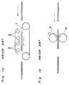
- Figs. 1a and 1b depict a known heating device for heating the image receiving sheet having thereon such a toner or colored image.
- the device of Fig. 1a is an oven type one in which a paper placed on a transport means 1 is indirectly heated by a plurality of heaters 2 disposed above the transport means 1.
- the device of Fig. 1b is a contact type one which is provided with a heat roller 3 and a pressure roller 4.
- the heat roller 3 accommodates a halogen lamp or the like as a heating means.
- the pressure roller 4 applies pressure to the image receiving sheet supplied between it and the heat roller 3.
- heating the paper with the toner image thereon softens the thermoplastic resin contained in the toner and fixes the toner.
- heating the image receiving sheet having thereon the colored image expedites the coloring reaction of the colorless dye, resulting in a desirable image.
- This fact is disclosed in USP No. 4,576,891.
- the use of the aforementioned heating device can soften the thermoplastic pigment to add a gloss to the colored image.
- the device of Fig. 1a employing the indirect heating means can not satisfactorily smooth the thermoplastic resin or pigment. Therefore, this device can not produce a high gloss image.
- the relatively low efficiency of the heating means causes the device to be formed undesirably into a large size.
- the paper tends to be slightly curled by the heating and is occasionally brought into contact with one of the heaters. This fact causes the paper to be scorched or set on fire.
- thermoplastic resin or pigment softened by the heating is occasionally caused to adhere to the heat roller and causes an unintentional transfer thereof called "offset".
- the thermoplastic resin or pigment adhering to the heat roller is then transferred onto the paper in the subsequent image forming process, thus occasionally spoiling the next image.
- the heat roller requires a relatively large cleaning device, resulting disadvantageously in a large-sized heating device.
- Copying apparatuses having features similar to features b) to e) of appended claim 1 are known from the U.S. patents US-A-4,095,886 and US-A-3,997,262.
- the member passed around the heat roller and the separating roller is not an image glazing member, but a member which helps to transfer an image on a thermoplastic image material onto an image receiving material.
- a separating pawl is provided which contacts a roller to separate a sheet of paper from the roller to guide it towards a pair of discharge rollers.
- the image glazing device of the present invention is defined by the teaching of appended claim 1. It comprises a guide member positioned in the vicinity of the separation roller and forming a predetermined angle with the paper transport means of at least 10°.
- an image glazing device D of a prestage of the present invention for producing a glossy image is accommodated in an image forming apparatus H in which an image is formed with the use of a photosensitive material and an image receiving material.
- the image forming apparatus of Fig. 2 is a copying apparatus.
- the copying apparatus H is internally provided with a main drum 11 substantially at a central portion thereof, a photosensitive sheet supply roller 12 for supplying an unused photosensitive sheet, and a photosensitive sheet take-up roller 13 for taking up a used photosensitive sheet.
- the supply and take-up rollers 12 and 13 are located to the left of the main drum 11, as viewed in Fig. 2.
- the photosensitive sheet wound around the supply roller 12 is taken up by the take-up roller 13 by way of the main drum 11. In this configuration, one surface of the photosensitive sheet on which a large number of microcapsules are coated is directed outwards.
- a document platform 14 On an upper surface of the apparatus body is disposed a document platform 14, below which is disposed an optical system comprised of a plurality of light sources 15a, a plurality of mirrors 15b, and a lens assembly 15c.
- An original document placed on the document platform 14 is scanned by the optical system so that light reflected from the original document may be led to an exposure point P1 on the main drum 11.
- the microcapsules of the photosensitive sheet engaging with the main drum 11 partially harden to form a selectively hardened image.
- a paper supply cassette 16 for placing thereon image receiving sheets is detachably mounted in the apparatus body at a side portion thereof.
- a paper supply roller 16a for supplying the image receiving sheets, one at a time, is disposed above the paper supply cassette 16.
- Each image receiving sheet supplied from the paper supply cassette 16 stops when it has been brought into contact with a pair of rollers 16b disposed downstream of the paper supply roller 16a.
- a pressure roller 17 which is biased against the main drum 11 by virtue of a biasing mechanism (not shown). The location where the main drum 11 and the pressure roller 17 are in contact with each other is referred to as a pressure point P2.
- the surface of the photosensitive sheet on which the microcapsules are coated and one surface of the image receiving sheet to which developing material is caused to adhere are mated and subjected to pressure at the pressure point P2.
- the image receiving sheet which has once stopped at the paired rollers 16b is supplied to the pressure point P2 so that the leading edge of the photosensitive sheet having the selectively hardened image formed thereon may be coincident with the leading edge of the image receiving sheet.
- unhardened microcapsules of the photosensitive sheet are crushed so that colorless dye contained therein may flow out therefrom to effect coloring reaction by the action with the developing material of the image receiving sheet.
- a separating claw piece 18 is disposed in the vicinity of the pressure point P2 to separate the image receiving sheet from the photosensitive sheet.
- the image receiving sheet separated from the photosensitive sheet is then transported towards the image glazing device D by means of a transport belt 19 adjacent to the pressure roller 17.
- the image glazing device D is positioned substantially below the take-up roller 13 at a left-hand side portion inside the apparatus body, as viewed in Fig. 2.
- the image formed on the image receiving sheet is turned into a high gloss image by the image glazing device D and is discharged onto a paper discharge tray 21 by means of a pair of paper discharge rollers 20. Accordingly, the paired paper discharge rollers 20 and the paper discharge tray 21 are located downstream of the image glazing device D in reference to the direction of feed of the image receiving sheet.
- Fig. 3 depicts the image glazing device D1 for producing a glossy image according to a prestage of the present invention.
- the image glazing device D1 is comprised of a heat roller 31, a roller 32 spaced from the heat roller 31, an image glazing belt 33 passed around the rollers 31 and 32, a back-up roller 34 biased against the heat roller 31 and a cleaning roller 35 for cleaning the image glazing belt 33.
- the image glazing belt 33 is a belt for producing the glossy image and rotates in the clockwise direction, as viewed in Fig. 3, upon rotation of the diameter of the heat roller 31 and the roller 32.
- the roller 32 has a diameter smaller than the heat roller 31 has.
- the image receiving sheet transported by the image glazing belt 33 is separated therefrom at a location where the roller 32 is provided.
- the roller 32 constitutes a separating portion for separating the image receiving sheet from the image glazing belt and is hereinafter referred to as a separation roller.
- the cleaning roller 35 removes thermoplastic resin or the like adhering to the image glazing belt 33.
- the cleaning roller 35 is not necessarily required, since the amount of the thermoplastic resin or the like which may adhere to the image glazing belt 33 is negligible.
- a material having a smooth surface and superior resistance to heat is preferably employed as the image glazing belt 33. It is also desirable that the material to be employed as the image glazing belt 33 be superior in mold-releasing characteristic, flexibility and durability. Polyester, polyimide, polyethyl ether ketone, polyphenylene sulfide, fluorine resin, silicone resin or the like is employed as the material of the image glazing belt 33.
- the desirable thickness of the image glazing belt 33 is approximately between 0.02 and 5 mm.
- the image glazing belt 33 has the form of an endless belt. Otherwise, the presence of a joint connecting opposite ends of the material of the image glazing belt 33 complicates the control for this belt. Furthermore, the endless belt can eliminate waste at the joint.
- the heat roller 31 is internally provided with a heating means comprised of, for example, a halogen lamp or lamps (not shown) and is controlled in temperature by a temperature sensor 36 which is in contact with the image glazing belt 33.
- the controlling temperature is in the neighborhood of the softening point of the thermoplastic pigment coated on the image receiving sheet approximately 125 °C.
- the image receiving sheet is pressed against the image glazing belt 33 by the back-up roller 34.
- the pressure applied to the image receiving sheet is approximately 4 kg/cm2.
- a paper transport guide 37 is provided immediately below the image glazing belt 33 and downstream of the back-up roller 34 in reference to the direction of feed of the image receiving sheet.
- the former is heated by the latter so that the coloring reaction may be expedited and gloss may be imparted to the colored image due to the presence of the thermoplastic pigment or resin of the image portion of the image receiving sheet.
- the image receiving sheet is subjected to pressure between the heat roller 31 and the back-up roller 34, thereby rendering the thermoplastic pigment to be smoothed and raised in glossiness.
- the image receiving sheet is then transported downstream along the paper transport guide 37. As the image receiving sheet travels farther away from the heat roller 31, it is gradually cooled down and reaches a condition such that it becomes easily separated from the image glazing belt 33.
- the image receiving sheet has reached the separation roller 32, it is separated from the image glazing belt 33 because the image glazing belt 33 is turned up by the separation roller 32.
- the separation of the image receiving sheet from the image glazing belt 33 is performed at a location where the separation roller 32 is provided.
- the offset can be prevented by changing the diameter of the separation roller 32 in accordance with the temperature of the image receiving sheet at the separation roller 32 or the rotating speed of the image glazing belt 33.
- the curvature of the image receiving sheet during the separation depends upon the diameter of the separation roller 32 whereas the rotating speed of the image glazing belt 33 equals to the traveling speed of the image receiving sheet.
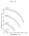
- Fig. 4 is a graph indicative of the relationship between the separation rate and the temperature at the separating portion of the separation roller when the diameter of the separation roller 32 has been changed.
- oblique lines indicate areas where no offset takes place.
- the temperature at the separating portion of the separation roller should not be set too low.
- the diameter of the separation roller 32 is 10 mm, desirable processing without any offset can be achieved at a temperature approximately below 80 °C. This temperature is relatively high, and therefore, it is not necessary to lengthen the image glazing belt 33 or to provide any fan, resulting in a small-sized device. Furthermore, the processing period of time can be shortened.
- the larger diameter of the separation roller 32 requires the lower temperature at the separating portion for the purpose of avoiding any offset.
- the smaller diameter of the separation roller 32 would cause no offset even when the temperature at the separating portion is somewhat high.
- FIG. 5 depicts an embodiment of an image glazing device D2 of the invention, provided with a guide member 40 in the vicinity of the separation roller 32.
- the guide member 40 forms a predetermined acute angle ⁇ with a paper transport plane formed by the paper transport guide 37.
- the angle is hereinafter referred to as a separation angle.
- the image receiving sheet which has been transported as far as the separation roller 32 travels along the guide member 40 and is then separated from the image glazing belt 33. In this event, the acute separation angle facilitates the separation and causes no offset.
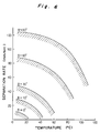
- Fig. 6 is a graph indicative of the relationship between the separation rate and the temperature at the separating portion of the separation roller when the separation angle ⁇ has been changed.
- oblique lines indicate areas where no offset takes place.
- the separation angle ⁇ of the guide member 40 is preferably set to an angle greater than 30° but should be at least greater than an angle of 10° in practical use. Most preferably, the separation angle ⁇ should be set to an angle greater than 60°. When the separation angle ⁇ is greater than 60°, the separation can be done at a relatively high separation rate of 50 mm/sec even when the temperature of the image receiving sheet is about 80 °C. Such conditions enable the image glazing processing to be desirably performed within a relatively short period of time using a small-sized device. Furthermore, as the temperature of the image receiving sheet or the separation rate becomes lower, the separation angle ⁇ can be reduced. The separation angle ⁇ , therefore, should be set in accordance with the temperature, and the separation rate.
- the presence of the guide member 40 facilitates the separation of the image receiving sheet from the image glazing belt 33 and prevents offset from taking place.
- an image glazing device of the present invention is applicable to the case where a toner image is required to be glazed.
- thermoelectric heating means may be provided in the vicinity of the upstream one of the two rollers between which an image glazing belt is passed.
Description
- The present invention relates to an image glazing device for applying a gloss to an image which has been formed on a paper using toner or coloring dye. In this device, the image is subjected to heat, pressure or the like when the gloss is applied thereto.
- In a method of forming an image on a paper, a photosensitive member having photoconductivity is electrically charged and exposed to light reflected from an original document so that an electrostatic latent image may be formed thereon. Then, toner is caused to adhere to the electrostatic latent image and transferred onto paper to form a visible toner image thereon.
- USP No. 4,399,209 discloses another method in which a photosensitive sheet coated with a large number of microcapsules and an image receiving sheet coated with developing material are used. Each of the microcapsules contains photo-setting material and colorless dye which is colored by the action of the developing material coated on the image receiving sheet. When the photosensitive sheet is exposed to light reflected from an original document, the microcapsules coated thereon are partially hardened to selectively form a hardened image. The image receiving sheet is then overlapped on the photosensitive sheet and subjected to pressure so that unhardened microcapsules may be crushed. In this situation, the colorless dye which flows out of the crushed microcapsules is colored by the developing material of the image receiving sheet to form a colored image. USP No. 4,576,891 discloses such a coloring reaction.
- Figs. 1a and 1b depict a known heating device for heating the image receiving sheet having thereon such a toner or colored image. The device of Fig. 1a is an oven type one in which a paper placed on a transport means 1 is indirectly heated by a plurality of
heaters 2 disposed above the transport means 1. The device of Fig. 1b is a contact type one which is provided with a heat roller 3 and apressure roller 4. The heat roller 3 accommodates a halogen lamp or the like as a heating means. Thepressure roller 4 applies pressure to the image receiving sheet supplied between it and the heat roller 3. - In the method of utilizing the photosensitive member having photoconductivity, heating the paper with the toner image thereon softens the thermoplastic resin contained in the toner and fixes the toner.
- In the method disclosed in USP No. 4,399,209, heating the image receiving sheet having thereon the colored image expedites the coloring reaction of the colorless dye, resulting in a desirable image. This fact is disclosed in USP No. 4,576,891. Furthermore, as disclosed in USP No. 4,554,235, if thermoplastic pigment is coated on the image receiving sheet, the use of the aforementioned heating device can soften the thermoplastic pigment to add a gloss to the colored image.
- However, the device of Fig. 1a employing the indirect heating means can not satisfactorily smooth the thermoplastic resin or pigment. Therefore, this device can not produce a high gloss image. Besides, the relatively low efficiency of the heating means causes the device to be formed undesirably into a large size. Moreover, the paper tends to be slightly curled by the heating and is occasionally brought into contact with one of the heaters. This fact causes the paper to be scorched or set on fire.
- In the device of Fig. 1b, the thermoplastic resin or pigment softened by the heating is occasionally caused to adhere to the heat roller and causes an unintentional transfer thereof called "offset". In other words, the thermoplastic resin or pigment adhering to the heat roller is then transferred onto the paper in the subsequent image forming process, thus occasionally spoiling the next image. To prevent this, the heat roller requires a relatively large cleaning device, resulting disadvantageously in a large-sized heating device.
- An image glazing device having the feature a) to e) of appended claim 1 is described in the document EP-A-0 301 585 which forms a prior art document according to Art. 51(3) and (4)EPC for all designated states. This document additionally describes a separating claw piece provided in the vicinity of the separation roller to readily execute the separation between the image receiving material and the image glazing member.
- Copying apparatuses having features similar to features b) to e) of appended claim 1 are known from the U.S. patents US-A-4,095,886 and US-A-3,997,262. However, in these apparatuses the member passed around the heat roller and the separating roller is not an image glazing member, but a member which helps to transfer an image on a thermoplastic image material onto an image receiving material. In the device according to document US-A-3,997,262, a separating pawl is provided which contacts a roller to separate a sheet of paper from the roller to guide it towards a pair of discharge rollers.
- It is the object of the present invention to provide an image glazing device having a simple construction by which an image receiving material can reliably be separated from an image glazing member which is passed around two rollers.
- The image glazing device of the present invention is defined by the teaching of appended claim 1. It comprises a guide member positioned in the vicinity of the separation roller and forming a predetermined angle with the paper transport means of at least 10°.
- These and other objects and features of the present invention will become more apparent from the following description taken in conjunction with the preferred embodiment thereof with reference to the accompanying drawings, throughout which like parts are designated by like reference numerals, and in which:
- Fig. 1a is a schematic view of a conventional heating device;
- Fig. 1b is a schematic view of another conventional heating device;
- Fig. 2 is a schematic sectional view of an image forming apparatus accommodating an image glazing device according to a prestage of the present invention;
- Fig. 3 is a schematic side view of the image glazing device according to a prestage of the present invention;
- Fig. 4 is a graph indicative of the relationship between the temperature at the separating portion of a separation roller and the separation rate when the diameter of a separation roller changes;
- Fig. 5 is a view similar to Fig. 3, which particularly shows an image glazing device according to the present invention; and
- Fig. 6 is a graph indicative of the relationship between the temperature of the separating portion and the separation rate when the separation angle formed between a guide member and a paper transport plane changes.
- Referring first to Fig. 2, an image glazing device D of a prestage of the present invention for producing a glossy image is accommodated in an image forming apparatus H in which an image is formed with the use of a photosensitive material and an image receiving material. The image forming apparatus of Fig. 2 is a copying apparatus.
- The copying apparatus H is internally provided with a
main drum 11 substantially at a central portion thereof, a photosensitivesheet supply roller 12 for supplying an unused photosensitive sheet, and a photosensitive sheet take-up roller 13 for taking up a used photosensitive sheet. The supply and take-up rollers main drum 11, as viewed in Fig. 2. The photosensitive sheet wound around thesupply roller 12 is taken up by the take-up roller 13 by way of themain drum 11. In this configuration, one surface of the photosensitive sheet on which a large number of microcapsules are coated is directed outwards. - On an upper surface of the apparatus body is disposed a
document platform 14, below which is disposed an optical system comprised of a plurality oflight sources 15a, a plurality ofmirrors 15b, and alens assembly 15c. An original document placed on thedocument platform 14 is scanned by the optical system so that light reflected from the original document may be led to an exposure point P1 on themain drum 11. As a result, the microcapsules of the photosensitive sheet engaging with themain drum 11 partially harden to form a selectively hardened image. - A
paper supply cassette 16 for placing thereon image receiving sheets is detachably mounted in the apparatus body at a side portion thereof. Apaper supply roller 16a for supplying the image receiving sheets, one at a time, is disposed above thepaper supply cassette 16. Each image receiving sheet supplied from thepaper supply cassette 16 stops when it has been brought into contact with a pair ofrollers 16b disposed downstream of thepaper supply roller 16a. Below themain drum 11 is positioned apressure roller 17, which is biased against themain drum 11 by virtue of a biasing mechanism (not shown). The location where themain drum 11 and thepressure roller 17 are in contact with each other is referred to as a pressure point P2. The surface of the photosensitive sheet on which the microcapsules are coated and one surface of the image receiving sheet to which developing material is caused to adhere are mated and subjected to pressure at the pressure point P2. The image receiving sheet which has once stopped at the pairedrollers 16b is supplied to the pressure point P2 so that the leading edge of the photosensitive sheet having the selectively hardened image formed thereon may be coincident with the leading edge of the image receiving sheet. At the pressure point P2, unhardened microcapsules of the photosensitive sheet are crushed so that colorless dye contained therein may flow out therefrom to effect coloring reaction by the action with the developing material of the image receiving sheet. - A separating
claw piece 18 is disposed in the vicinity of the pressure point P2 to separate the image receiving sheet from the photosensitive sheet. The image receiving sheet separated from the photosensitive sheet is then transported towards the image glazing device D by means of atransport belt 19 adjacent to thepressure roller 17. The image glazing device D is positioned substantially below the take-uproller 13 at a left-hand side portion inside the apparatus body, as viewed in Fig. 2. The image formed on the image receiving sheet is turned into a high gloss image by the image glazing device D and is discharged onto apaper discharge tray 21 by means of a pair ofpaper discharge rollers 20. Accordingly, the pairedpaper discharge rollers 20 and thepaper discharge tray 21 are located downstream of the image glazing device D in reference to the direction of feed of the image receiving sheet. - Fig. 3 depicts the image glazing device D1 for producing a glossy image according to a prestage of the present invention. The image glazing device D1 is comprised of a
heat roller 31, aroller 32 spaced from theheat roller 31, animage glazing belt 33 passed around therollers roller 34 biased against theheat roller 31 and a cleaningroller 35 for cleaning theimage glazing belt 33. Theimage glazing belt 33 is a belt for producing the glossy image and rotates in the clockwise direction, as viewed in Fig. 3, upon rotation of the diameter of theheat roller 31 and theroller 32. Theroller 32 has a diameter smaller than theheat roller 31 has. The image receiving sheet transported by theimage glazing belt 33 is separated therefrom at a location where theroller 32 is provided. Accordingly, theroller 32 constitutes a separating portion for separating the image receiving sheet from the image glazing belt and is hereinafter referred to as a separation roller. The cleaningroller 35 removes thermoplastic resin or the like adhering to theimage glazing belt 33. However, the cleaningroller 35 is not necessarily required, since the amount of the thermoplastic resin or the like which may adhere to theimage glazing belt 33 is negligible. - A material having a smooth surface and superior resistance to heat is preferably employed as the
image glazing belt 33. It is also desirable that the material to be employed as theimage glazing belt 33 be superior in mold-releasing characteristic, flexibility and durability. Polyester, polyimide, polyethyl ether ketone, polyphenylene sulfide, fluorine resin, silicone resin or the like is employed as the material of theimage glazing belt 33. The desirable thickness of theimage glazing belt 33 is approximately between 0.02 and 5 mm. Preferably, theimage glazing belt 33 has the form of an endless belt. Otherwise, the presence of a joint connecting opposite ends of the material of theimage glazing belt 33 complicates the control for this belt. Furthermore, the endless belt can eliminate waste at the joint. - The
heat roller 31 is internally provided with a heating means comprised of, for example, a halogen lamp or lamps (not shown) and is controlled in temperature by atemperature sensor 36 which is in contact with theimage glazing belt 33. The controlling temperature is in the neighborhood of the softening point of the thermoplastic pigment coated on the image receiving sheet approximately 125 °C. The image receiving sheet is pressed against theimage glazing belt 33 by the back-uproller 34. The pressure applied to the image receiving sheet is approximately 4 kg/cm². Apaper transport guide 37 is provided immediately below theimage glazing belt 33 and downstream of the back-uproller 34 in reference to the direction of feed of the image receiving sheet. - When the image receiving sheet having thereon a colored image has reached the
heat roller 31, the former is heated by the latter so that the coloring reaction may be expedited and gloss may be imparted to the colored image due to the presence of the thermoplastic pigment or resin of the image portion of the image receiving sheet. In this event, the image receiving sheet is subjected to pressure between theheat roller 31 and the back-uproller 34, thereby rendering the thermoplastic pigment to be smoothed and raised in glossiness. The image receiving sheet is then transported downstream along thepaper transport guide 37. As the image receiving sheet travels farther away from theheat roller 31, it is gradually cooled down and reaches a condition such that it becomes easily separated from theimage glazing belt 33. When the image receiving sheet has reached theseparation roller 32, it is separated from theimage glazing belt 33 because theimage glazing belt 33 is turned up by theseparation roller 32. - In this way, the separation of the image receiving sheet from the
image glazing belt 33 is performed at a location where theseparation roller 32 is provided. According to various experiments made so far, the offset can be prevented by changing the diameter of theseparation roller 32 in accordance with the temperature of the image receiving sheet at theseparation roller 32 or the rotating speed of theimage glazing belt 33. The curvature of the image receiving sheet during the separation depends upon the diameter of theseparation roller 32 whereas the rotating speed of theimage glazing belt 33 equals to the traveling speed of the image receiving sheet. - Fig. 4 is a graph indicative of the relationship between the separation rate and the temperature at the separating portion of the separation roller when the diameter of the
separation roller 32 has been changed. In this graph, oblique lines indicate areas where no offset takes place. - According to the graph of Fig. 4, no offset takes place by lowering the separation rate even when the temperature of the separating portion is high. For example, in a certain image forming apparatus in which the separation rate i.e., the rotating speed of the
image glazing belt 33 is set to 40 mm/sec, the offset would be caused unless the temperature of the separating portion is lower than 30 °C when the diameter of theseparation roller 32 is 20 mm. To lower the temperature of the separating portion below 30 °C, it is necessary to lengthen the distance between theheat roller 31 and theseparation roller 32 to prolong the cooling period of time or to forcibly cool the image receiving sheet by providing a fan or the like between theheat roller 31 and theseparation roller 32. However, this is disadvantageous in that the processing time would be increased or the device made to be large in size. To avoid such a disadvantage, the temperature at the separating portion of the separation roller should not be set too low. When the diameter of theseparation roller 32 is 10 mm, desirable processing without any offset can be achieved at a temperature approximately below 80 °C. This temperature is relatively high, and therefore, it is not necessary to lengthen theimage glazing belt 33 or to provide any fan, resulting in a small-sized device. Furthermore, the processing period of time can be shortened. - In the case where the separation rate is increased, the larger diameter of the
separation roller 32 requires the lower temperature at the separating portion for the purpose of avoiding any offset. In contrast, the smaller diameter of theseparation roller 32 would cause no offset even when the temperature at the separating portion is somewhat high. - It is to be noted that because the
separation roller 32 having a very small diameter extremely fatigues theimage glazing belt 33, the diameter thereof should be suitably determined in view of the combination of the separation rate and the temperature of the separating portion. Fig. 5 depicts an embodiment of an image glazing device D2 of the invention, provided with aguide member 40 in the vicinity of theseparation roller 32. Theguide member 40 forms a predetermined acute angle ϑ with a paper transport plane formed by thepaper transport guide 37. The angle is hereinafter referred to as a separation angle. The image receiving sheet which has been transported as far as theseparation roller 32 travels along theguide member 40 and is then separated from theimage glazing belt 33. In this event, the acute separation angle facilitates the separation and causes no offset. - Fig. 6 is a graph indicative of the relationship between the separation rate and the temperature at the separating portion of the separation roller when the separation angle ϑ has been changed. In this graph, oblique lines indicate areas where no offset takes place.
- As is clear from this graph, the greater the separation angle ϑ is, the broader the area is where no offset takes place, even when the temperature at the separating portion or the separation rate is high. The separation angle ϑ of the
guide member 40 is preferably set to an angle greater than 30° but should be at least greater than an angle of 10° in practical use. Most preferably, the separation angle ϑ should be set to an angle greater than 60°. When the separation angle ϑ is greater than 60°, the separation can be done at a relatively high separation rate of 50 mm/sec even when the temperature of the image receiving sheet is about 80 °C. Such conditions enable the image glazing processing to be desirably performed within a relatively short period of time using a small-sized device. Furthermore, as the temperature of the image receiving sheet or the separation rate becomes lower, the separation angle ϑ can be reduced. The separation angle ϑ, therefore, should be set in accordance with the temperature, and the separation rate. - As described above, the presence of the
guide member 40 facilitates the separation of the image receiving sheet from theimage glazing belt 33 and prevents offset from taking place. - It is to be noted that although this embodiment has been described with respect to the glazing of a colored image, an image glazing device of the present invention is applicable to the case where a toner image is required to be glazed.
- It is further to be noted that in this embodiment, although a heat roller is employed as a roller accommodating a heating means, the heating means may be provided in the vicinity of the upstream one of the two rollers between which an image glazing belt is passed.
Claims (2)
- An image glazing device, for use in an image forming apparatus, for applying gloss to an image formed on an image receiving material, comprisinga) a heat roller (31) and a separation roller (32) disposed subsequent to a portion for development of an image on an image receiving material, whereby the diameter of said separation roller is less than that of said heat roller;b) an image glazing member (33) passed around and rotatably driven by said heat roller and said separation roller for applying gloss to said image;c) a heating means associated with said heat roller (31) for heating said image glazing member;d) a pressure means (34) biased against said heat roller for applying pressure to said image;e) a paper transport means (37) juxtapositioned to said image glazing member for transporting said image receiving material from said heat roller to said separation roller and thereby cooling said image receiving material; andf) a guide member (40) positioned in the vicinity of the separation roller and forming a predetermined angle (ϑ) with said paper transport means (37) of at least 10°.
- The image glazing device according to claim 1, wherein said separation roller (32) has a diameter not greater than 10 mm.
Applications Claiming Priority (4)
| Application Number | Priority Date | Filing Date | Title |
|---|---|---|---|
| JP32199287A JPH01161346A (en) | 1987-12-18 | 1987-12-18 | Image brightening device |
| JP321993/87 | 1987-12-18 | ||
| JP321992/87 | 1987-12-18 | ||
| JP32199387A JPH01161347A (en) | 1987-12-18 | 1987-12-18 | Image brightening device |
Publications (3)
| Publication Number | Publication Date |
|---|---|
| EP0320973A2 EP0320973A2 (en) | 1989-06-21 |
| EP0320973A3 EP0320973A3 (en) | 1990-10-24 |
| EP0320973B1 true EP0320973B1 (en) | 1995-06-21 |
Family
ID=26570653
Family Applications (1)
| Application Number | Title | Priority Date | Filing Date |
|---|---|---|---|
| EP88121122A Expired - Lifetime EP0320973B1 (en) | 1987-12-18 | 1988-12-16 | Image glazing device |
Country Status (3)
| Country | Link |
|---|---|
| US (1) | US4931618A (en) |
| EP (1) | EP0320973B1 (en) |
| DE (1) | DE3854043T2 (en) |
Families Citing this family (17)
| Publication number | Priority date | Publication date | Assignee | Title |
|---|---|---|---|---|
| US5208628A (en) * | 1988-01-14 | 1993-05-04 | Sharp Kabushiki Kaisha | Image forming apparatus |
| US5053829A (en) * | 1988-10-03 | 1991-10-01 | Xerox Corporation | Heat and pressure fuser with non-symmetrical nip pressure |
| US4978560A (en) * | 1989-07-13 | 1990-12-18 | The Mead Corporation | Hot roll glosser method with glossing temperature below free air glass transistion temperature of resin utilized |
| JP2538685B2 (en) * | 1989-12-19 | 1996-09-25 | シャープ株式会社 | Image receiving sheet transfer device |
| US5254165A (en) * | 1989-12-19 | 1993-10-19 | Sharp Kabushiki Kaisha | Image forming apparatus |
| US5153656A (en) * | 1991-10-28 | 1992-10-06 | Eastman Kodak Company | Image forming apparatus including transfer and fixing member |
| US5155536A (en) * | 1991-10-28 | 1992-10-13 | Eastman Kodak Company | Image forming apparatus including toner image fixing device using fusing sheets |
| JPH05142959A (en) * | 1991-11-20 | 1993-06-11 | Konica Corp | Color image forming device |
| US5254426A (en) * | 1992-04-01 | 1993-10-19 | Eastman Kodak Company | Method of making a projection viewable transparency |
| US5256507A (en) * | 1992-04-01 | 1993-10-26 | Eastman Kodak Company | Method of fusing electrostatographic toners to provide differential gloss |
| US5258256A (en) * | 1992-04-01 | 1993-11-02 | Eastman Kodak Company | Method of fusing electrostatographic toners to provide enhanced gloss |
| US5234784A (en) * | 1992-04-01 | 1993-08-10 | Eastman Kodak Company | Method of making a projection viewable transparency comprising an electrostatographic toner image |
| US5410394A (en) * | 1993-12-16 | 1995-04-25 | Xerox Corporation | Three roller design eliminates free span belt heating of integral heating fusing belt |
| US5584960A (en) * | 1994-09-01 | 1996-12-17 | Nep Systems, Inc. | Apparatus for joining plastic materials together |
| JP3254991B2 (en) * | 1995-11-13 | 2002-02-12 | ミノルタ株式会社 | Fixing device |
| AU1062697A (en) * | 1995-12-22 | 1997-07-17 | Minnesota Mining And Manufacturing Company | Surface restructuring process and imaged media produced therefrom |
| US5927189A (en) * | 1997-12-30 | 1999-07-27 | Kimberly-Clark Worldwide, Inc. | Method and apparatus for thermal fusing with two textured endless belts |
Family Cites Families (13)
| Publication number | Priority date | Publication date | Assignee | Title |
|---|---|---|---|---|
| DE1182958B (en) * | 1962-02-10 | 1964-12-03 | Agfa Ag | Device for the production of photographic images and printing forms with the help of heat |
| JPS5753595B2 (en) * | 1973-09-07 | 1982-11-13 | ||
| US3864709A (en) * | 1973-10-04 | 1975-02-04 | Tektronix Inc | Apparatus for processing recording material |
| NL179851C (en) * | 1976-03-18 | 1986-11-17 | Oce Van Der Grinten N V P A Oc | DEVICE FOR TRANSFERRING AND FIXING IMAGES. |
| US4399209A (en) * | 1981-11-12 | 1983-08-16 | The Mead Corporation | Transfer imaging system |
| JPS5974577A (en) * | 1982-10-20 | 1984-04-27 | Canon Inc | Fixing device |
| US4554235A (en) * | 1984-05-17 | 1985-11-19 | The Mead Corporation | Microencapsulated transfer imaging system employing developer sheet and discontinuous layer of thermoplastic pigment |
| US4576891A (en) * | 1984-06-15 | 1986-03-18 | The Mead Corporation | Photosensitive microcapsules useful in polychromatic imaging having radiation absorber |
| JPS61122666A (en) * | 1984-11-19 | 1986-06-10 | Canon Inc | Processor for improving picture quality |
| JPS6136756A (en) * | 1984-07-30 | 1986-02-21 | Canon Inc | Colored light-transmissive image forming sheet |
| DE3643144A1 (en) * | 1985-12-19 | 1987-06-25 | Fuji Photo Film Co Ltd | HEAT DEVELOPMENT DEVICE |
| US4761311A (en) * | 1987-02-19 | 1988-08-02 | The Mead Corporation | Process for glossing a developer sheet and an apparatus useful therein |
| EP0301585A3 (en) * | 1987-07-30 | 1990-08-16 | Sharp Kabushiki Kaisha | Method of producing a glossy image and device for effecting said method |
-
1988
- 1988-12-13 US US07/283,839 patent/US4931618A/en not_active Expired - Lifetime
- 1988-12-16 EP EP88121122A patent/EP0320973B1/en not_active Expired - Lifetime
- 1988-12-16 DE DE3854043T patent/DE3854043T2/en not_active Expired - Fee Related
Non-Patent Citations (2)
| Title |
|---|
| PATENT ABSTRACTS OF JAPAN, vol. 10, no. 190 (P-474)[2246], 4th July 1986, page 130 P 474 ; & JP-A-61 36 756 ; & US-A-4 780 742 * |
| PATENT ABSTRACTS OF JAPAN, vol. 10, no. 308 (P-508)[2364], 21st October 1986, page 161 P 508 ; & JP-A-61 122 666 ; & US-A-4 780 742 * |
Also Published As
| Publication number | Publication date |
|---|---|
| US4931618A (en) | 1990-06-05 |
| EP0320973A2 (en) | 1989-06-21 |
| DE3854043D1 (en) | 1995-07-27 |
| DE3854043T2 (en) | 1996-03-07 |
| EP0320973A3 (en) | 1990-10-24 |
Similar Documents
| Publication | Publication Date | Title |
|---|---|---|
| EP0320973B1 (en) | Image glazing device | |
| US5247336A (en) | Image fusing apparatus having heating and cooling devices | |
| US4427285A (en) | Direct duplex printing on pre-cut copy sheets | |
| US5126797A (en) | Method and apparatus for laminating toner images on receiving sheets | |
| EP0301585A2 (en) | Method of producing a glossy image and device for effecting said method | |
| JPH0719100B2 (en) | Fixing device | |
| US20050271432A1 (en) | Image heating apparatus and image forming apparatus | |
| US5998761A (en) | Variable dwell fuser | |
| US5153656A (en) | Image forming apparatus including transfer and fixing member | |
| JPH03233586A (en) | Fixing device | |
| JPH0325481A (en) | Fixing device | |
| US5155536A (en) | Image forming apparatus including toner image fixing device using fusing sheets | |
| US5126781A (en) | Image recording apparatus | |
| US5311269A (en) | Toner image finishing apparatus | |
| US4806733A (en) | Radiant glossing apparatus for glossing developer sheets and a process for using the same | |
| EP1400872B1 (en) | Image forming apparatus with belt fixing device for simultaneous fixing of both sides of a duplex print | |
| JPH02301759A (en) | Image forming device provided with for giving glossiness to image | |
| JP2002148973A (en) | Image forming apparatus | |
| US20030143005A1 (en) | Transfer material conveying apparatus and image forming apparatus | |
| JP2592937B2 (en) | Fixing device | |
| JPH08272240A (en) | Heating device and image forming device | |
| JP2538685B2 (en) | Image receiving sheet transfer device | |
| JPH01161346A (en) | Image brightening device | |
| JPH0727196B2 (en) | Image glossing device | |
| JP2801225B2 (en) | Image forming device |
Legal Events
| Date | Code | Title | Description |
|---|---|---|---|
| PUAI | Public reference made under article 153(3) epc to a published international application that has entered the european phase |
Free format text: ORIGINAL CODE: 0009012 |
|
| 17P | Request for examination filed |
Effective date: 19881216 |
|
| AK | Designated contracting states |
Kind code of ref document: A2 Designated state(s): DE FR GB |
|
| PUAL | Search report despatched |
Free format text: ORIGINAL CODE: 0009013 |
|
| AK | Designated contracting states |
Kind code of ref document: A3 Designated state(s): DE FR GB |
|
| 17Q | First examination report despatched |
Effective date: 19930810 |
|
| GRAA | (expected) grant |
Free format text: ORIGINAL CODE: 0009210 |
|
| AK | Designated contracting states |
Kind code of ref document: B1 Designated state(s): DE FR GB |
|
| REF | Corresponds to: |
Ref document number: 3854043 Country of ref document: DE Date of ref document: 19950727 |
|
| ET | Fr: translation filed | ||
| PLBE | No opposition filed within time limit |
Free format text: ORIGINAL CODE: 0009261 |
|
| STAA | Information on the status of an ep patent application or granted ep patent |
Free format text: STATUS: NO OPPOSITION FILED WITHIN TIME LIMIT |
|
| 26N | No opposition filed | ||
| REG | Reference to a national code |
Ref country code: GB Ref legal event code: IF02 |
|
| PGFP | Annual fee paid to national office [announced via postgrant information from national office to epo] |
Ref country code: FR Payment date: 20041208 Year of fee payment: 17 |
|
| PGFP | Annual fee paid to national office [announced via postgrant information from national office to epo] |
Ref country code: DE Payment date: 20041209 Year of fee payment: 17 |
|
| PGFP | Annual fee paid to national office [announced via postgrant information from national office to epo] |
Ref country code: GB Payment date: 20041215 Year of fee payment: 17 |
|
| PG25 | Lapsed in a contracting state [announced via postgrant information from national office to epo] |
Ref country code: GB Free format text: LAPSE BECAUSE OF NON-PAYMENT OF DUE FEES Effective date: 20051216 |
|
| PG25 | Lapsed in a contracting state [announced via postgrant information from national office to epo] |
Ref country code: DE Free format text: LAPSE BECAUSE OF NON-PAYMENT OF DUE FEES Effective date: 20060701 |
|
| GBPC | Gb: european patent ceased through non-payment of renewal fee |
Effective date: 20051216 |
|
| PG25 | Lapsed in a contracting state [announced via postgrant information from national office to epo] |
Ref country code: FR Free format text: LAPSE BECAUSE OF NON-PAYMENT OF DUE FEES Effective date: 20060831 |
|
| REG | Reference to a national code |
Ref country code: FR Ref legal event code: ST Effective date: 20060831 |