EP0320573B1 - Alignment tool for laser beam delivery systems and method of alignment - Google Patents
Alignment tool for laser beam delivery systems and method of alignment Download PDFInfo
- Publication number
- EP0320573B1 EP0320573B1 EP88113869A EP88113869A EP0320573B1 EP 0320573 B1 EP0320573 B1 EP 0320573B1 EP 88113869 A EP88113869 A EP 88113869A EP 88113869 A EP88113869 A EP 88113869A EP 0320573 B1 EP0320573 B1 EP 0320573B1
- Authority
- EP
- European Patent Office
- Prior art keywords
- laser beam
- laser
- delivery system
- monitoring
- tool
- Prior art date
- Legal status (The legal status is an assumption and is not a legal conclusion. Google has not performed a legal analysis and makes no representation as to the accuracy of the status listed.)
- Expired - Lifetime
Links
- 238000000034 method Methods 0.000 title claims description 23
- 238000012544 monitoring process Methods 0.000 claims description 29
- 238000004891 communication Methods 0.000 claims description 3
- 238000001914 filtration Methods 0.000 claims description 3
- 230000000694 effects Effects 0.000 description 6
- 230000009977 dual effect Effects 0.000 description 4
- 230000033001 locomotion Effects 0.000 description 4
- 230000007935 neutral effect Effects 0.000 description 4
- 238000012937 correction Methods 0.000 description 3
- 238000010586 diagram Methods 0.000 description 3
- 210000004209 hair Anatomy 0.000 description 3
- 238000004519 manufacturing process Methods 0.000 description 3
- 239000004033 plastic Substances 0.000 description 3
- 230000000007 visual effect Effects 0.000 description 3
- 230000000712 assembly Effects 0.000 description 2
- 238000000429 assembly Methods 0.000 description 2
- 230000005540 biological transmission Effects 0.000 description 2
- 238000005516 engineering process Methods 0.000 description 2
- 239000011521 glass Substances 0.000 description 2
- CPBQJMYROZQQJC-UHFFFAOYSA-N helium neon Chemical compound [He].[Ne] CPBQJMYROZQQJC-UHFFFAOYSA-N 0.000 description 2
- 239000000463 material Substances 0.000 description 2
- 238000005259 measurement Methods 0.000 description 2
- 230000005019 pattern of movement Effects 0.000 description 2
- 230000009466 transformation Effects 0.000 description 2
- 235000013175 Crataegus laevigata Nutrition 0.000 description 1
- 229920004142 LEXAN™ Polymers 0.000 description 1
- XAGFODPZIPBFFR-UHFFFAOYSA-N aluminium Chemical compound [Al] XAGFODPZIPBFFR-UHFFFAOYSA-N 0.000 description 1
- 229910052782 aluminium Inorganic materials 0.000 description 1
- 238000004873 anchoring Methods 0.000 description 1
- 238000013473 artificial intelligence Methods 0.000 description 1
- 238000004140 cleaning Methods 0.000 description 1
- 239000012141 concentrate Substances 0.000 description 1
- 238000005520 cutting process Methods 0.000 description 1
- 230000002452 interceptive effect Effects 0.000 description 1
- 150000002500 ions Chemical class 0.000 description 1
- 230000001788 irregular Effects 0.000 description 1
- 239000003562 lightweight material Substances 0.000 description 1
- 238000012423 maintenance Methods 0.000 description 1
- 230000003287 optical effect Effects 0.000 description 1
- 238000012545 processing Methods 0.000 description 1
- 238000007493 shaping process Methods 0.000 description 1
- 210000003813 thumb Anatomy 0.000 description 1
Images


Classifications
-
- G—PHYSICS
- G01—MEASURING; TESTING
- G01B—MEASURING LENGTH, THICKNESS OR SIMILAR LINEAR DIMENSIONS; MEASURING ANGLES; MEASURING AREAS; MEASURING IRREGULARITIES OF SURFACES OR CONTOURS
- G01B11/00—Measuring arrangements characterised by the use of optical techniques
- G01B11/26—Measuring arrangements characterised by the use of optical techniques for measuring angles or tapers; for testing the alignment of axes
- G01B11/27—Measuring arrangements characterised by the use of optical techniques for measuring angles or tapers; for testing the alignment of axes for testing the alignment of axes
- G01B11/272—Measuring arrangements characterised by the use of optical techniques for measuring angles or tapers; for testing the alignment of axes for testing the alignment of axes using photoelectric detection means
-
- B—PERFORMING OPERATIONS; TRANSPORTING
- B23—MACHINE TOOLS; METAL-WORKING NOT OTHERWISE PROVIDED FOR
- B23K—SOLDERING OR UNSOLDERING; WELDING; CLADDING OR PLATING BY SOLDERING OR WELDING; CUTTING BY APPLYING HEAT LOCALLY, e.g. FLAME CUTTING; WORKING BY LASER BEAM
- B23K26/00—Working by laser beam, e.g. welding, cutting or boring
- B23K26/02—Positioning or observing the workpiece, e.g. with respect to the point of impact; Aligning, aiming or focusing the laser beam
- B23K26/04—Automatically aligning, aiming or focusing the laser beam, e.g. using the back-scattered light
- B23K26/042—Automatically aligning the laser beam
- B23K26/043—Automatically aligning the laser beam along the beam path, i.e. alignment of laser beam axis relative to laser beam apparatus
Definitions
- This invention relates to a tool for use in aligning a laser beam delivery system containing at least one rotating joint and having one or more rotatable laser optics, and, more particularly, to an improved tool for use in aligning both angular and translational position of a laser beam at a rotating joint of the laser beam is delivery system.
- laser devices to undertake various fabrication, cutting, shaping, inspecting and other manufacturing and related operations is realizing greatly increased popularity in various industries throughout the world.
- manipulator devices such as robots and the like to deliver the laser to a particular point in space or onto a particular object
- the beam delivery system may take the form of a dynamic manipulator device, such as a robotic device having one or more rotating joints.
- a dynamic manipulator device such as a robotic device having one or more rotating joints.
- a laser beam delivery system includes one or more rotating joints which carry rotatable laser optics, various translational and angular position errors of such laser beam can find their way into the system.
- Position errors of a laser beam can be the cause of variable power levels, power loss, poor beam quality and various beam locational errors which cause inefficiencies and unreliability of the laser at its output location. Obviously, such inefficiencies and position inaccuracies are unacceptable in today's demanding applications. Consequently, it is critical to the efficient and accurate delivery of a laser beam to minimize the translational and angular errors of the laser beam as it is directed through its delivery system by various laser beam optics, mirror packages or the like.
- One method which has been used in the industry to correct deviations of a laser beam along its delivery path is to cover the end of a portion of the laser beam delivery system with a diffusing device having a set of intersecting cross hairs drawn or etched onto one side thereof. Appropriate optics of the laser beam delivery system are thereafter adjusted to appropriately center the laser beam in the cross hairs, which preferably are located at the center of that particular portion of the laser beam delivery system. While this technique can be used to generally center the laser beam within the delivery system, its accuracy is not reliable and it is not useful in correcting for angular deviations of the laser beam. Moreover, this technique is quite inconvenient to implement in applications where such laser beam delivery system includes one or more rotating joints and one or more rotatable laser optics or mirror packages to guide the beam therethrough.
- An alignment tool was also made by Spectra-Physics Inc. of San Jose, California for correcting laser beam rotational errors at moving joints of laser beam delivery systems.
- the Spectra-Physics tool required disassembling the beam delivery system and performing alignment as the system was being rebuilt.
- the Spectra-Physics tool comprised a focusing lens which received the laser beam and collimated the beam to a point on a screen spaced from such collimating lens at the focal length thereof. In this way, the angular errors of the beam would be isolated by the collimating effect of the lens, and any angular error could be adjusted out of the laser beam by monitoring the movement of the beam on the screen and making appropriate adjustments to the laser optics.
- the Spectra-Physics tool was large, limited solely to the removal of angular beam errors, and was difficult to use in that it required disassembly of the beam delivery system to perform the alignment procedures.
- U.S. Patent 4,483,618 which issued to M. Hamar on November 20, 1984.
- the Hamar measurement system utilizes a plurality of mirrors to place a virtual image of a sensing device at an otherwise inaccessible physical point for the purpose of accurately determining the position of that point relative to another predetermined physical point.
- the system is described with respect to an apparatus for measuring distances such as for locating a point on a machine part, or locating a point on a position scale. Consequently, the Hamar '618 patent fails to address the problem of aligning the angular and translational position of a laser beam delivery system containing a rotating joint and one or more rotatable laser optics.
- Patent 4,566,202 which issued to M. Hamar on January 28, 1986, describes a tool containing a laser source which is used to align a rotatable part about the mechanical axis of a tool. Again, this laser apparatus fails to address the need for an alignment tool for aligning both angular and translational position of a laser beam in a laser beam delivery system.
- DE-A1-2847718 discloses an alignment and direction meter in which a beam of light is directed against a photo-electric converter unit, which measures the deflection of the beam in orthogonal X and Y axes.
- the beam of light is split and directed against a second converter unit, and of a difference between the outputs of the converter units may be utilised to determine angular misalignment of the laser beam.
- the beam is passed through a focusing lens on entry into the device, whilst in another embodiment the unfocused beam is directed against the converter units.
- An electronic control system produces output signals purporting to represent alignment variation or directional variation.
- an improved tool for use in both angular and translational position of a laser beam at a rotating joint of a laser beam delivery system having one or more rotatable laser optics.
- the tool includes a tool chassis which receives a laser beam which has been directed along a laser beam axis to the rotating joint of the delivery system and the tool chassis.
- the tool further includes structure for mounting the tool chassis on the rotatable part of a rotating joint of a laser beam delivery system to be aligned in place of a rotatable laser optic which is normally attached on that rotatable part. In this way, the chassis can be rotated about the joint.
- the tool further includes a position monitor for monitoring the laser beam received relative to a two dimensional coordinate system during rotation of the tool, and a laser beam focusing lens which focuses at least a portion of the laser beam received such that translational deviations of the received beam are eliminated from that focused portion of the beam.
- a position monitor for monitoring the laser beam received relative to a two dimensional coordinate system during rotation of the tool
- a laser beam focusing lens which focuses at least a portion of the laser beam received such that translational deviations of the received beam are eliminated from that focused portion of the beam.
- angular orientation of the received laser beam can be isolated and monitored when passed through the focusing lens, and translational position of the received beam can be monitored when not focused by the focusing lens. In this way, both translational and angular errors in the laser beam can be determined.
- FIG. 1 illustrates a preferred embodiment of an alignment tool 10 of the present invention.
- FIGS. 2-5 illustrate additional details of alignment tool 10 of FIG. 1
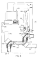
- FIG. 6 illustrates alignment tool 10 as it might be attached to a rotatable joint 16b of a laser beam delivery system 12.
- Alignment tool 10 is shown as comprising tool chassis 20 (made up of chassis walls 22a-d), mounting means 23 (shown as plate 23) attached to one end of chassis 20, and cover 31 attached at the opposite end thereof.
- Chassis walls 22a-d are shown as pairs of oppositely disposed side walls in the figures only as an example.
- Chassis 20 might preferably be an extruded, one piece, rectangular structure as shown; or could be formed from several pieces and feature any outside conformation desired.
- mounting means 23 includes means for receiving a laser beam, as illustrated by aperture 21, to enable the entrance of a laser beam which has been directed along a laser beam axis (i.e. see laser beam 15 and laser beam axis A shown in FIG. 6) to aperture 21 and the rotating joint 16b of the laser beam delivery system 12. It is preferred to attenuate the laser beam intensity entering tool 10 by the use of one or more filtering devices, such as neutral density filter 53 shown in FIGS. 3 and 4. Neutral density filter 53 is shown as being mounted at a slight angle to beam axis A within filter mount 54 and filter insert 55 fitted within aperture 21. Filter insert 55 further includes a relatively large aperture 55a to enable unencumbered passage of a laser beam therethrough.
- filtering devices such as neutral density filter 53 shown in FIGS. 3 and 4.
- Neutral density filter 53 is shown as being mounted at a slight angle to beam axis A within filter mount 54 and filter insert 55 fitted within aperture 21.
- Filter insert 55 further includes a relatively large aperture 55a to enable unenc
- filter 53 in a non-normal relationship relative the beam axis A is important to ensure that the filter does not reflect a substantial portion of the laser beam back towards its source, as such beam reflection might interfere with proper laser beam operation and may damage the laser source itself. It is contemplated that filter mount 54 might preferably be threadedly mounted within filter insert 55 to facilitate removal of such filter for cleaning, maintenance and the like. It should be noted that the exact location of any filters (e.g. 53) within tool 10 is not critical, and can be modified as desired.
- Focusing lens package 40 is preferably mounted within chassis 20 by one or more removeable bolts (e.g. button head screw 57). Focusing lens package 40 comprises a beam focusing lens 41 held within lens holder 42, which is in turn threadedly mounted within lens mount 43. Lens mount 43 is preferably located within chassis 20 by one or more locating pins 45. Lens holder 42 is preferably threadedly mounted within lens mount 43 to provide limited longitudinal adjustability of focusing lens 41 along laser beam axis A. As will be discussed in greater detail below, such adjustment ensures proper focusing of the laser beam onto a monitoring means or screen 24 at the distal end of the alignment tool 10.
- lens mount set screw 44 can be tightened to maintain that desired position.
- a plurality of holes H are illustrated in the forward portion of lens holder 42 to facilitate turning of lens holder 42 relative lens mount 43 for adjustment of focusing lens 41.
- lens mount 43 comprise a substantially L-shaped bracket (e.g. 43a) to support lens mount 43 within chassis 20 without interfering with access to holes H.
- Lens mount 43 is preferably attached within chassis 20 by one or more buttonhead screws 57 anchoring bracket 43a to chassis wall 22b.
- Lens access cover 33 is utilized to cover access opening 32, and access cover 33 is shown as being mounted by a pair of staggered standoffs 50 which are held in place by oppositely disposed buttonhead screws 51 and washers 52. Any manner of removably attaching cover 33 could equally be utilized, to provide ready access to lens package 40 from the exterior of tool 10.
- Laser beam focusing lens 41 is provided to focus at least a portion of received laser beam 15 such that translational deviations of the received laser beam are eliminated when such beam passes through the focusing lens, thereby enabling angular orientation or position of the received laser beam 15 to be isolated and monitored on monitoring means or screen 24.
- Any laser beam entering focusing lens 41 parallel to the lens axis will be focused to a point on that axis, while any beam entering lens 41 at an angle to the lens axis will be focused to a point offset from such axis. This offset will be equal to the focal length of lens 41 multiplied by the sine of the angle at which the laser beam is entering lens 41.
- focusing lens 41 may be moved between an operating position, wherein it focuses at least a portion of received beam 15, and a non-operating position, wherein received beam 15 continues along its axis A in an unfocused condition.
- an additional neutral density filter 47 is shown as being attached to the downstream side of lens holder 42. This neutral density filter 47 is purely optional, and its use will depend upon whether additional attenuation of the laser beam intensity is required.
- first folding mirror 60 and second folding mirror 70 are used herein to facilitate the provision of a tool 10 having an effective length which can accommodate the focal length of the particular focusing lens 41 being utilized.
- this folding mirror arrangement is utilized to minimize the overall length of alignment tool 10 while accommodating the required focal length of focusing lens 41.
- the focal length of focusing lens 41 is approximately one meter. It should be noted that a focusing lens having a longer focal length could be used to further improve the accuracy of this alignment tool (as could a shorter focal length lens where less accuracy is acceptable). By folding the laser beam travel path within tool 10, overall length of the tool can be minimized without compromising the accuracy of the system.
- First folding mirror 60 is preferably a front surfaced mirror to obviate potential distortion, inaccuracies, or other interference which might result from use of rear surfaced mirrors and the like.
- Mirror 60 is supported by a mirror support block 6l, and is preferably located by a plurality of locator pins 64.
- Mirror support block 61 is preferably attached to chassis 20 and chassis walls 22 by one or more buttonhead screws 62 or similar attachment means. It is preferable to provide access to folding mirror 60 from the exterior of chassis 20, such as by providing an access opening 34 which is normally covered by cover plate 35. It is contemplated that cover plate 35 might preferably be held in place by a pair of staggered threaded standoffs 65 attached at their distal ends by buttonhead screws 66 and washers 67.
- Locator pins 64 are utilized to ensure accurate and repeatable location of mirror 60 in order to direct the received beam properly toward second folding mirror 70, as illustrated in FIG. 4.
- Second folding mirror 70 is similarly mounted on mirror support block 71, and located by a plurality of locator pins 74. Second folding mirror 70 receives the reflected laser beam from first folding mirror 60 and directs it toward monitoring means 24. Second folding mirror 70 is substantially identical in structure to first folding mirror 60. Obviously, any number of folding mirrors such as described herein could be utilized to accommodate any particular focal length of focusing lens 41, as desired.
- Mirror support block 71 is similarly attached to chassis 20 by a plurality of screws 72 and washers 73, and access opening 36 formed in the side of chassis 20 is similarly provided for second folding mirror 70, with cover plate 37 attached by a pair of threaded standoffs 75, buttonhead screws 76 and washers 77.
- Monitoring means 24 is merely a screen onto which received laser beam 15 is directed.
- Screen 24 can comprise simply a diffusing end plate (e.g. end plate 31) for alignment tool 10, wherein end plate 31 is simply a thickness of translucent material such as frosted Lexan® (as available from General Electric Company) or similar material (e.g. glass, plastic, etc.) which will enable an aligning operator to visually perceive the laser beam directed thereonto.
- end plate 31 is simply a thickness of translucent material such as frosted Lexan® (as available from General Electric Company) or similar material (e.g. glass, plastic, etc.) which will enable an aligning operator to visually perceive the laser beam directed thereonto.
- a piece of paper might be attached over a clear end plate 31 (i.e. glass or clear plastic) to provide an effective screen 24 upon which the laser beam position can be viewed.
- an additional magnifying lens 26 be mounted adjacent the laser beam viewing screen 24 to facilitate an operator's visual monitoring of the position of such laser beam on the screen.
- an adjustable holder 28 be mounted a convenient distance away from screen 24, such as by standoff 27.
- Clamp stud 30 can be used to mount standoff 27 to rear cover 31 (which may be part of the same structure as screen 24), and a threadedly mounted thumb nut 29 can be used to adjustably connect lens 26 and lens holder 28 to standoff 27.
- magnifying lens 26 can be selectively aligned with a particular laser beam spot on screen 24 to permit more accurate visual monitoring thereof.
- the subject alignment tool will be mounted on the rotatable part of a rotating joint (e.g. 16b of FIG. 6) of a laser beam delivery system (e.g. 12).
- alignment tool 10 will preferably be mounted on the rotatable part of laser beam delivery system 12 in place of a rotatable laser optic which normally is attached to such rotatable part such that tool 10 can receive laser beam 15 along its axis of transmission A.
- alignment tool 10 is attached to rotatable part (or joint) 16b via adapter unit 19 designed to attach alignment tool 10 to part 16b in the same way in which a laser optic or mirror package (not shown) is normally attached thereto.
- laser optic shall connote any optic, mirror package or the like utilized in a laser beam delivery system to route the beam from its source to the desired end use point.
- Laser optic 17a shows an example of a mirror optic which is normally attached to a rotatable part 16a of laser beam delivery system 12.
- alignment tool 10 has been attached in place of such laser optic at rotating joint 16b.
- laser beam 15 is received by alignment tool 10 through aperture 21 and is passed through focusing lens 41 and directed onto monitoring screen 24.
- An alignment operator then visually perceives the focused laser beam upon screen 24 and marks the location of such beam spot on that screen.
- alignment tool 10 is rotated about rotating joint 16b to various positions such that a plurality of laser beam spots are monitored and marked on screen 24. It is preferred that at least 3 or 4 such marks (e.g.
- rotation of alignment tool 10 identifies a generally circular-shaped pattern of movement of the projected beam on screen 24 relative a two-dimensional coordinate system (e.g. an x-y coordinate system 83 as shown in FIG. 2), indicating angular deviations of laser beam 15.
- a two-dimensional coordinate system e.g. an x-y coordinate system 83 as shown in FIG. 2
- such patterns may be elliptical or non-uniform in appearance, but generally have a substantially "rounded" conformation.
- one or more of the laser optics e.g.
- optic 17a and/or l7b are adjusted such that the projected beam is as closely centered within the circular deviation pattern marked on screen 24 as possible. Most often, it is preferred to adjust only the mirror which directs the laser beam into rotating joint 16b and alignment tool 10 (i.e. laser optic 17b). Following such adjustment, joint 16b is again sequentially rotated to determine if any angular deviations remain in laser beam 15. These steps can be repeated until substantially all of the angular deviations have been removed.
- focusing lens 41 may be completely removed from alignment tool 10 by removing lens cover plate 33, loosening buttonhead screw (or screws) 57 attaching bracket 43a of lens mount 43 to chassis 20, and withdrawing focusing lens 41, lens holder 42 and lens mount 43 (i.e. lens package 40) from alignment tool 10. It is also contemplated that focusing lens 41 could be attached within chassis 20 in such a way as to be reciprocable between an operating position in which lens 41 focuses at least a portion of received laser beam 15, and a non-operating position wherein lens 41 does not focus laser beam 15.
- received laser beam 15 can be focused for alignment of angular deviations of the laser beam, and can remain unfocused for adjustment of translational deviations of such beam.
- received laser beam 15 will pass in an unfocused condition through alignment tool 10 and onto screen 24. Because the angular deviations of laser beam 15 have previously been removed by appropriate adjustments as described above, the unfocused portion of the beam effectively isolates translational deviations of beam 15 and can be utilized to monitor such translational deviations. Again, rotation of joint 16b and attached alignment tool 10 is sequentially completed and the orbit or path of the unfocused beam on screen 24 is plotted. Thereafter, appropriate adjustments are made to one or more of the preceding laser optic packages (e.g. laser optics 17a and/or 17b) in order to center the received laser beam 15 within the traced orbit of the unfocused beam on screen 24.
- the preceding laser optic packages e.g. laser optics 17a and/or 17b
- angular adjustments required to center the focused beam can most often be accomplished by adjustments of mirror package 17b by appropriately tightening or loosening orientational set screws thereof. Following correction for such angular deviations, often only adjustments to mirror package 17a will be required to correct for translational deviations as determined by alignment tool 10 with regard to the unfocused laser beam 15. In this way also, further adjustments to optic 17b (which had previously been adjusted for angular corrections) can be avoided at this time.
- any beam being monitored by the human eye must be a Class I level (e.g. see 21 C.F.R. ⁇ 1040, Performance Standards for Light-Emitting Products, and ANSI Z-136.1-1986, ANSI Standard for the Safe Use of Lasers, Laser Institute of America, Toledo, Ohio) in order to be within the Maximum Permissible Exposure (MPE) for that particular beam.
- MPE Maximum Permissible Exposure
- the Maximum Permissible Exposure is 3.9 x 10 e-7 Watts. If the two filters (e.g. 53 and 47) described above are utilized for alignment tool 10, and each of those filters has an optical density of 2.0, the maximum safe power of the laser source is 3.9mW. Obviously, if different filters are to be used, or if a laser source having different power values is to be used, the combination of filters and laser source must be matched to ensure that the tool operates within safe ranges.
- the visual monitoring screen 24 described above may be replaced by a dual axis position sensor, lateral effect photodiode or similar position sensitive quadrant detector having a series of electrodes (e.g. four) equally spaced about its periphery.
- lateral effect photodiode position sensors are available under the "SC" designation series from United Detector Technology (Hawthorne, California). These detectors would, of course, be utilized in conjunction with standard support electronics (not shown), as described in the literature available from the manufacturer such as United Detector Technology. The details of such support electronics are not critical to the instant invention, and will not be discussed further herein.
- a photodiode or sensor 180 can be mounted within tool chassis 120 at a distance from focusing lens 141 equal to the focal length of lens 141. Alignment tool 110 is shown with a mounting adapter unit 119 attached for illustration purposes.
- a laser beam 115 is received by alignment tool 110 along laser axis A′, passed through focusing lens package 140 and directed onto photodiode 180.
- Photodiode 180 could thereby be used to communicate the detected orbit of received beam 115 (whether focused through focusing lens 141 or as received in an unfocused condition) to a dual trace oscilloscope 182 and its screen pattern cross hairs 183 via communication link 181.
- oscilloscope 182 can be used to view the generally circular deviation patterns of the received laser beam 115 during rotation of tool 110.
- Such arrangement eliminates the need for an alignment operator to be physically within the range of motion of the laser delivery system, and eliminates the laser hazard associated with direct viewing of the beam.
- an appropriate photodiode 180 or a similar position sensitive photodetector laser sensing device also allows the alignment tool of the subject invention to be used with laser delivery systems featuring invisible laser beams. This also enables the alignment of a wider variety of laser beam power levels with a single tool. Necessary adjustments to appropriate laser optics can thereby be determined from the oscilloscope tracing pattern as described above with regard to the manual tracings on screen 24. Use of photodiode 180 and oscilloscope 182 would also normally obviate a need for use of filters to attenuate the laser beam's intensity.
- a laser alignment tool made in accordance herewith includes the ability to take advantage of a laser source external to the tool (i.e. the laser source typically part of the laser beam delivery system being aligned). Consequently, in many applications where the laser source of the beam delivery system can be maintained within proper power level ranges, the laser beam of the laser delivery system can be used for alignment procedures with the subject tool.
- an independent laser source can be utilized with the subject tool if the primary beam of the delivery system to be aligned is not (or cannot be) used. The independent laser source must first be aligned in a coaxial manner with the primary beam of the laser delivery system to insure optimum effectiveness of the alignment tool in aligning the system.
- FIG. 8 illustrates an alignment tool 210 further including means 290 for splitting received laser beam 215 into a plurality of beam portions (i.e. B1 and B2), whereby first portion B1 continues to pass through focusing lens 241 to be directed onto a photodiode 280 or similar position sensing device as described above, while second portion B2 remains unfocused and is directed onto a second dual position photodiode or similar position sensing device 283.
- angular orientation of received laser beam 215 can be determined by monitoring first portion B1 of the split beam, as described above with respect to FIG. 7.
- photodiodes 280 and 283 or similar sensing devices would include standard support electronics, and can be connected via standard communication links or connectors 281 and 284, respectively, to one or more dual trace oscilloscopes, as described above.
- photodiodes 280 and 283 could alternately be connected to a data acquisition system 282, such as a microprocessing unit, computer, or the like, wherein angular and translational positions of the laser beam could be compiled to determine alignment errors of the received laser beam 215.
- a data acquisition system 282 such as a microprocessing unit, computer, or the like
- the laser beam orbit patterns monitored by photodiodes 280 and 283 could be fed into data acquisition system 282, wherein such data would be fit to equations for ellipses or similar circular patterns so that the mathematical centers thereof could be computed accurately.
- the software of data acquisition system 282 could then provide adjustment commands for various adjustable parts of the laser beam delivery system 212 (e.g. adjustment screws for mirror packages 217a and 2l7b) in order to correct alignment errors determined by tool 210 to properly align laser beam 215 at rotating joint 216b.
- adjustment commands can be implemented either manually by an alignment operator, or automatically through servo-mechanism packages 295 attached directly to the appropriate mirror packages 217a and 217b of delivery system 212.
- adjustment commands would be issued by data acquisition system 282 and communicated to servo-mechanisms 295 via output connectors 285.
- servo-mechanism packages 295 or similar automatic adjusting devices would be attached to the appropriate mirror packages by removing a back plate of such mirror packages. Actual attachment of servo-mechanisms 295, of course, may vary between particular applications according to particular characteristics of the mirror packages or similar optics.
- U.S. Patent 4,457,625 which issued to A. Greenleaf et al. on July 3, 1984, concerns a laser measuring system utilizing a plurality of laser interferometers whose sensors supply data regarding the x, y and z coordinates of a retroreflector which is moved along the surface of an object.
- a central computer is utilized to store the data input from the laser sensing devices and to reduce such data to a profile of the object's surface by using mathematical techniques.
- the computer also utilizes the data input to control a plurality of servocontrollers to steer the interferometers.
- the data points collected by the computer from the laser sensing devices are accumulated in sufficient number to enable the computer to mathematically fit the data to a profile by undertaking iterative techniques.
- the disclosure of the Greenleaf et al. patent is hereby incorporated herein by reference.
- the Merry et al. patent discloses the use of a motive assembly or drive mechanism attached to each of the tracking mirrors which direct the associated laser output beam of a particular interferometer onto the center of the retroreflector, such motive assemblies moving the mirrors to maintain the interferometer beams incident on the center of the retroreflector.
- a digital computer control system controls the tracking mirrors by sending signals to the motive assemblies based upon the position data received from the interferometer output signals.
- the disclosure of the Merry et al. patent is hereby incorporated herein by reference.
- the interferometer system of the Merry et al. patent is also embodied in a laser tracking system, commonly available in the industry from Chesapeake Laser Systems, Inc. of Lanham, Maryland. Consequently, it is contemplated that the software and controls for laser servocorrection devices available in the industry can be adapted to the unique laser alignment tool of the subject invention to facilitate provision of a more fully automated embodiment thereof, as shown and described with respect to FIG. 8 herein.
- FIG. 9 A preferred logic diagram for such a partially or fully automated alignment tool is illustrated in FIG. 9.
- software for such data acquisition system 282 would necessarily include transformation equations or similar adjustments to take into account various peculiarities of any particular laser delivery system 212, such as number and type of laser optics/mirror packages, degrees of freedom of such packages, and the like. If transformation equations are utilized, they can be preprogrammed, computed from user input, down loaded from the delivery system's control, or computed from measured beam deflect ions upon mirror/optic perturbations.
- data acquisition system 282 must be able to accommodate for special problems such as binding joints and loose mirror connections which might cause irregular beam movements. As illustrated in FIG. 9, such problems could be identified and flagged for correction by the alignment operator if necessary.
- the data acquisition system 282 could be independent of or integrated into the machine control for a particular laser delivery system being aligned. Peculiarities of a particular laser beam delivery system to be aligned (e.g. the system's configuration and details of particular mirror packages to be adjusted) might be entered manually into the data acquisition system 282 by the alignment operator through a keyboard input or the like, or automatically entered through a direct connection with the machine control of the delivery system 212 itself.
- an alignment tool made in accordance herewith can provide a fully automated system having the capability of artificial intelligence, whereby the alignment tool can be "taught" peculiarities of a wide variety of laser beam delivery systems to thereby provide an alignment tool which can most effectively and efficiently align substantially any delivery system quickly and accurately.
- the data acquisition system 282 could further be programmed to provide a readout as to the accuracy of its resulting alignment for each particular delivery system.
- the degree to which the subject alignment tool is automated depends upon the user's requirements and degree of sophistication desired.
- the unique aspects of the subject alignment tool can be provided in an alignment tool having a substantial amount of manual operation involved, or can be supplied in a substantially fully automated mode.
- the alignment tool of the subject invention might be marketed in modular form, whereby the user could determine his relative needs for automation and obtain only those portions necessary for his particular applications.
- those with low-powered and relatively safe laser beam power sources could utilize the simpliest version as described with regard to FIGS. 1-6; wherein others might utilize one of the other embodiments for various safety reasons or the like.
- the alignment tool 210 of FIG. 8 could be utilized with one or more oscilloscopes, or could be attached to a microprocessing unit or personal computer.
- tool 210 could be utilized with or without the servo-mechanisms 295 for automatically implementing adjustment commands determined by data acquisition system 282.
- alignment tool 10 might be modified to include equipment to automatically selectively move focusing lens 41 between its operating position and a non-operating position on command.
Description
- This invention relates to a tool for use in aligning a laser beam delivery system containing at least one rotating joint and having one or more rotatable laser optics, and, more particularly, to an improved tool for use in aligning both angular and translational position of a laser beam at a rotating joint of the laser beam is delivery system.
- The use of laser devices to undertake various fabrication, cutting, shaping, inspecting and other manufacturing and related operations is realizing greatly increased popularity in various industries throughout the world. As many uses for laser devices include repetitious manufacturing operations which preferably incorporate manipulator devices such as robots and the like to deliver the laser to a particular point in space or onto a particular object, it is often necessary to deliver a laser beam along and/or through various parts of a moving laser beam delivery system. The beam delivery system may take the form of a dynamic manipulator device, such as a robotic device having one or more rotating joints. In order to accomplish the transmission of the laser beam through the laser beam delivery system, it is often necessary to route the laser beam with various moveable and non-moveable optic structures, mirror packages and the like. Where a laser beam delivery system includes one or more rotating joints which carry rotatable laser optics, various translational and angular position errors of such laser beam can find their way into the system.
- Position errors of a laser beam can be the cause of variable power levels, power loss, poor beam quality and various beam locational errors which cause inefficiencies and unreliability of the laser at its output location. Obviously, such inefficiencies and position inaccuracies are unacceptable in today's demanding applications. Consequently, it is critical to the efficient and accurate delivery of a laser beam to minimize the translational and angular errors of the laser beam as it is directed through its delivery system by various laser beam optics, mirror packages or the like.
- One method which has been used in the industry to correct deviations of a laser beam along its delivery path is to cover the end of a portion of the laser beam delivery system with a diffusing device having a set of intersecting cross hairs drawn or etched onto one side thereof. Appropriate optics of the laser beam delivery system are thereafter adjusted to appropriately center the laser beam in the cross hairs, which preferably are located at the center of that particular portion of the laser beam delivery system. While this technique can be used to generally center the laser beam within the delivery system, its accuracy is not reliable and it is not useful in correcting for angular deviations of the laser beam. Moreover, this technique is quite inconvenient to implement in applications where such laser beam delivery system includes one or more rotating joints and one or more rotatable laser optics or mirror packages to guide the beam therethrough.
- An alignment tool was also made by Spectra-Physics Inc. of San Jose, California for correcting laser beam rotational errors at moving joints of laser beam delivery systems. The Spectra-Physics tool, however, required disassembling the beam delivery system and performing alignment as the system was being rebuilt. In particular, the Spectra-Physics tool comprised a focusing lens which received the laser beam and collimated the beam to a point on a screen spaced from such collimating lens at the focal length thereof. In this way, the angular errors of the beam would be isolated by the collimating effect of the lens, and any angular error could be adjusted out of the laser beam by monitoring the movement of the beam on the screen and making appropriate adjustments to the laser optics. However, the Spectra-Physics tool was large, limited solely to the removal of angular beam errors, and was difficult to use in that it required disassembly of the beam delivery system to perform the alignment procedures.
- A laser measurement system is shown in U.S. Patent 4,483,618 which issued to M. Hamar on November 20, 1984. However, the Hamar measurement system utilizes a plurality of mirrors to place a virtual image of a sensing device at an otherwise inaccessible physical point for the purpose of accurately determining the position of that point relative to another predetermined physical point. In this way, the system is described with respect to an apparatus for measuring distances such as for locating a point on a machine part, or locating a point on a position scale. Consequently, the Hamar '618 patent fails to address the problem of aligning the angular and translational position of a laser beam delivery system containing a rotating joint and one or more rotatable laser optics. Similarly, U.S. Patent 4,566,202, which issued to M. Hamar on January 28, 1986, describes a tool containing a laser source which is used to align a rotatable part about the mechanical axis of a tool. Again, this laser apparatus fails to address the need for an alignment tool for aligning both angular and translational position of a laser beam in a laser beam delivery system.
- As a result, heretofore there has not been available in the industry a relatively simple, easy to use, compact, laser alignment tool which provides for efficient alignment of both angular and translational position errors of a laser beam. U.S. Patent 4,618,759, which issued to G. Muller et al. on October 21, 1986, sets forth an arrangement for compensating for offset and angular errors of a laser utilized in a processing or measuring machine. However, the beam position control arrangement set forth in Muller et al. is designed to determine and compensate for errors associated with a laser device which is generally stationary, and is designed for permanent application in a particular machine to constantly monitor the beam accuracy. The Muller et al. device, therefore, is not suited for use in a portable tool for aligning position errors of a laser beam at a rotating joint of an articulated laser beam delivery system.
- DE-A1-2847718 discloses an alignment and direction meter in which a beam of light is directed against a photo-electric converter unit, which measures the deflection of the beam in orthogonal X and Y axes. The beam of light is split and directed against a second converter unit, and of a difference between the outputs of the converter units may be utilised to determine angular misalignment of the laser beam.
- In one embodiment disclosed in DE-A1-2847718, the beam is passed through a focusing lens on entry into the device, whilst in another embodiment the unfocused beam is directed against the converter units.
- An electronic control system produces output signals purporting to represent alignment variation or directional variation.
- Thus, whilst laser alignment is increasingly becoming more and more critical with regard to various moveable laser beam delivery systems, heretofore there has not been a tool adapted for aligning both angular and translational position of a laser beam at a rotating joint of a delivery system which can easily be utilized without disassembly of a major part of the delivery system, and which is portable and applicable to a wide variety of delivery systems. Prior art alignment tools were limited either to translational or angular alignment, were unwieldy and impractical to use in applications including rotatable laser optics, were not reasonably portable and/or applicable to various delivery systems, or required disassembly and reassembly of a major portion of the delivery system.
- It is an object of this invention to obviate the above-described problems and shortcomings of the laser alignment tools and systems heretofore available in the industry.
- It is another object of the present invention to provide an improved tool for use in aligning both angular and translational position of a laser beam.
- It is yet another object of the present invention to provide a tool for use in aligning both angular and translational position of a laser beam at a rotating joint of a laser beam delivery system having one or more rotatable laser optics.
- It is also an object of the present invention to provide a tool which can be adapted to a variety of laser beam delivery systems, and which can be utilized in alignment procedures without substantial disassembly of the laser beam delivery system.
- In accordance with one aspect of the present invention, there is provided an improved tool for use in both angular and translational position of a laser beam at a rotating joint of a laser beam delivery system having one or more rotatable laser optics. The tool includes a tool chassis which receives a laser beam which has been directed along a laser beam axis to the rotating joint of the delivery system and the tool chassis. The tool further includes structure for mounting the tool chassis on the rotatable part of a rotating joint of a laser beam delivery system to be aligned in place of a rotatable laser optic which is normally attached on that rotatable part. In this way, the chassis can be rotated about the joint. The tool further includes a position monitor for monitoring the laser beam received relative to a two dimensional coordinate system during rotation of the tool, and a laser beam focusing lens which focuses at least a portion of the laser beam received such that translational deviations of the received beam are eliminated from that focused portion of the beam. In conjunction with the position monitor, angular orientation of the received laser beam can be isolated and monitored when passed through the focusing lens, and translational position of the received beam can be monitored when not focused by the focusing lens. In this way, both translational and angular errors in the laser beam can be determined.
- While the specification concludes with claims particularly pointing out and distinctly claiming the present invention, it is believed the same will be better understood from the following description taken in conjunction with the accompanying drawings in which:
- FIG. 1 is a top plan view of a preferred embodiment of an alignment tool for laser beam delivery systems made in accordance with the subject invention;
- FIG. 2 is a right end view of the alignment tool of FIG. 1;
- FIG. 3 is a left end view of the alignment tool of FIG. 1;
- FIG. 4 is a vertical cross-sectional view of the alignment tool shown in FIG. 1, taken along line 4-4 thereof;
- FIG. 5 is a front elevational view of the alignment tool of FIG. 1;
- FIG. 6 is a schematic illustration of the alignment tool of FIG. 1, illustrated as being attached to the rotatable part of a rotating joint of a laser beam delivery system;
- FIG. 7 is a schematic illustration of an alternate embodiment of an alignment tool made in accordance with the subject invention;
- FIG. 8 is a schematic view of yet another alternate embodiment of an alignment tool made in accordance with the subject invention, illustrated as being attached to the rotatable part of a rotating joint of a laser delivery system; and
- FIG. 9 is a flow chart diagram of the preferred logic for an alignment tool made in accordance herewith, especially useful where the tool is partially or fully automated.
- Referring now to the drawings in detail, wherein like numerals indicate the same elements throughout the views, FIG. 1 illustrates a preferred embodiment of an
alignment tool 10 of the present invention. FIGS. 2-5 illustrate additional details ofalignment tool 10 of FIG. 1, and FIG. 6 illustratesalignment tool 10 as it might be attached to arotatable joint 16b of a laserbeam delivery system 12.Alignment tool 10 is shown as comprising tool chassis 20 (made up ofchassis walls 22a-d), mounting means 23 (shown as plate 23) attached to one end ofchassis 20, andcover 31 attached at the opposite end thereof.Chassis walls 22a-d are shown as pairs of oppositely disposed side walls in the figures only as an example.Chassis 20 might preferably be an extruded, one piece, rectangular structure as shown; or could be formed from several pieces and feature any outside conformation desired. - As best seen in the end view of FIG. 3, mounting means 23 includes means for receiving a laser beam, as illustrated by
aperture 21, to enable the entrance of a laser beam which has been directed along a laser beam axis (i.e. seelaser beam 15 and laser beam axis A shown in FIG. 6) to aperture 21 and the rotatingjoint 16b of the laserbeam delivery system 12. It is preferred to attenuate the laser beamintensity entering tool 10 by the use of one or more filtering devices, such asneutral density filter 53 shown in FIGS. 3 and 4.Neutral density filter 53 is shown as being mounted at a slight angle to beam axis A withinfilter mount 54 and filter insert 55 fitted withinaperture 21.Filter insert 55 further includes a relativelylarge aperture 55a to enable unencumbered passage of a laser beam therethrough. The arrangement offilter 53 in a non-normal relationship relative the beam axis A is important to ensure that the filter does not reflect a substantial portion of the laser beam back towards its source, as such beam reflection might interfere with proper laser beam operation and may damage the laser source itself. It is contemplated that filter mount 54 might preferably be threadedly mounted withinfilter insert 55 to facilitate removal of such filter for cleaning, maintenance and the like. It should be noted that the exact location of any filters (e.g. 53) withintool 10 is not critical, and can be modified as desired. -
Laser beam 15 is thereby received bytool chassis 10 along beam axis A throughaperture 21, and thereafter continues along that same axis A through focusinglens package 40 mounted withinchassis 20. As seen best in FIG. 1, focusinglens package 40 is preferably mounted withinchassis 20 by one or more removeable bolts (e.g. button head screw 57). Focusinglens package 40 comprises abeam focusing lens 41 held withinlens holder 42, which is in turn threadedly mounted withinlens mount 43.Lens mount 43 is preferably located withinchassis 20 by one or more locating pins 45.Lens holder 42 is preferably threadedly mounted withinlens mount 43 to provide limited longitudinal adjustability of focusinglens 41 along laser beam axis A. As will be discussed in greater detail below, such adjustment ensures proper focusing of the laser beam onto a monitoring means orscreen 24 at the distal end of thealignment tool 10. - Once focusing
lens 41 has been properly positioned, lens mount setscrew 44 can be tightened to maintain that desired position. A plurality of holes H are illustrated in the forward portion oflens holder 42 to facilitate turning oflens holder 42relative lens mount 43 for adjustment of focusinglens 41. To further enable easy access to holes H, it is preferred that lens mount 43 comprise a substantially L-shaped bracket (e.g. 43a) to supportlens mount 43 withinchassis 20 without interfering with access to holesH. Lens mount 43 is preferably attached withinchassis 20 by one or more buttonhead screws 57anchoring bracket 43a tochassis wall 22b.Lens access cover 33 is utilized to cover access opening 32, and access cover 33 is shown as being mounted by a pair ofstaggered standoffs 50 which are held in place by oppositely disposed buttonhead screws 51 andwashers 52. Any manner of removably attachingcover 33 could equally be utilized, to provide ready access tolens package 40 from the exterior oftool 10. - Laser
beam focusing lens 41 is provided to focus at least a portion of receivedlaser beam 15 such that translational deviations of the received laser beam are eliminated when such beam passes through the focusing lens, thereby enabling angular orientation or position of the receivedlaser beam 15 to be isolated and monitored on monitoring means orscreen 24. Any laser beam entering focusinglens 41 parallel to the lens axis will be focused to a point on that axis, while anybeam entering lens 41 at an angle to the lens axis will be focused to a point offset from such axis. This offset will be equal to the focal length oflens 41 multiplied by the sine of the angle at which the laser beam is enteringlens 41. By properly locating focusinglens 41 at its focal length from monitoring means 24, angular deviations of receivedbeam 15 can be isolated and viewed on monitoring means 24. Further details of this position monitoring process will be discussed below. - It is contemplated that focusing
lens 41 may be moved between an operating position, wherein it focuses at least a portion of receivedbeam 15, and a non-operating position, wherein receivedbeam 15 continues along its axis A in an unfocused condition. It should also be noted that an additionalneutral density filter 47 is shown as being attached to the downstream side oflens holder 42. Thisneutral density filter 47 is purely optional, and its use will depend upon whether additional attenuation of the laser beam intensity is required. - Whether or not the focusing
lens 41 is in its operating or non-operating position, receivedlaser beam 15 will continue along axis A towardfirst folding mirror 60. It should be noted thatfirst folding mirror 60 andsecond folding mirror 70 are used herein to facilitate the provision of atool 10 having an effective length which can accommodate the focal length of the particular focusinglens 41 being utilized. In this regard, this folding mirror arrangement is utilized to minimize the overall length ofalignment tool 10 while accommodating the required focal length of focusinglens 41. In a preferred arrangement, the focal length of focusinglens 41 is approximately one meter. It should be noted that a focusing lens having a longer focal length could be used to further improve the accuracy of this alignment tool (as could a shorter focal length lens where less accuracy is acceptable). By folding the laser beam travel path withintool 10, overall length of the tool can be minimized without compromising the accuracy of the system. -
First folding mirror 60 is preferably a front surfaced mirror to obviate potential distortion, inaccuracies, or other interference which might result from use of rear surfaced mirrors and the like.Mirror 60 is supported by a mirror support block 6l, and is preferably located by a plurality of locator pins 64.Mirror support block 61 is preferably attached tochassis 20 and chassis walls 22 by one or more buttonhead screws 62 or similar attachment means. It is preferable to provide access to foldingmirror 60 from the exterior ofchassis 20, such as by providing an access opening 34 which is normally covered bycover plate 35. It is contemplated thatcover plate 35 might preferably be held in place by a pair of staggered threadedstandoffs 65 attached at their distal ends bybuttonhead screws 66 andwashers 67. As is the case with all the cover plates discussed herein, whilecover plate 35 could be removably attached by any means, it is contemplated that ifchassis 20 is made of lightweight material such as plastic, aluminum, or the like, the use of standoffs is preferred to provide a sturdy mounting system with good durability characteristics. Locator pins 64 are utilized to ensure accurate and repeatable location ofmirror 60 in order to direct the received beam properly towardsecond folding mirror 70, as illustrated in FIG. 4. -
Second folding mirror 70 is similarly mounted onmirror support block 71, and located by a plurality of locator pins 74.Second folding mirror 70 receives the reflected laser beam fromfirst folding mirror 60 and directs it toward monitoring means 24.Second folding mirror 70 is substantially identical in structure tofirst folding mirror 60. Obviously, any number of folding mirrors such as described herein could be utilized to accommodate any particular focal length of focusinglens 41, as desired.Mirror support block 71 is similarly attached tochassis 20 by a plurality ofscrews 72 andwashers 73, and access opening 36 formed in the side ofchassis 20 is similarly provided forsecond folding mirror 70, withcover plate 37 attached by a pair of threadedstandoffs 75, buttonhead screws 76 andwashers 77. -
Received beam 15 is thereby directed by folding mirrors 60 and 70, respectively, onto a monitoring means 4 which is optically located at a distance fromlens 41 equal to the focal length of focusinglens 41. In its simplest form, monitoring means 24 is merely a screen onto which receivedlaser beam 15 is directed.Screen 24 can comprise simply a diffusing end plate (e.g. end plate 31) foralignment tool 10, whereinend plate 31 is simply a thickness of translucent material such as frosted Lexan® (as available from General Electric Company) or similar material (e.g. glass, plastic, etc.) which will enable an aligning operator to visually perceive the laser beam directed thereonto. Similarly, a piece of paper might be attached over a clear end plate 31 (i.e. glass or clear plastic) to provide aneffective screen 24 upon which the laser beam position can be viewed. - Because the laser beam directed against
such screen 24 will be relatively small in size (especially when passing through focusing lens 41), it is preferred that anadditional magnifying lens 26 be mounted adjacent the laserbeam viewing screen 24 to facilitate an operator's visual monitoring of the position of such laser beam on the screen. As seen best in FIGS. 1, 2 and 4, it is preferred that anadjustable holder 28 be mounted a convenient distance away fromscreen 24, such as bystandoff 27.Clamp stud 30 can be used to mountstandoff 27 to rear cover 31 (which may be part of the same structure as screen 24), and a threadedly mountedthumb nut 29 can be used to adjustably connectlens 26 andlens holder 28 tostandoff 27. In this way, magnifyinglens 26 can be selectively aligned with a particular laser beam spot onscreen 24 to permit more accurate visual monitoring thereof. - In use, it is contemplated that the subject alignment tool will be mounted on the rotatable part of a rotating joint (e.g. 16b of FIG. 6) of a laser beam delivery system (e.g. 12). In particular, it is contemplated that
alignment tool 10 will preferably be mounted on the rotatable part of laserbeam delivery system 12 in place of a rotatable laser optic which normally is attached to such rotatable part such thattool 10 can receivelaser beam 15 along its axis of transmission A. As seen best in FIG. 6,alignment tool 10 is attached to rotatable part (or joint) 16b viaadapter unit 19 designed to attachalignment tool 10 topart 16b in the same way in which a laser optic or mirror package (not shown) is normally attached thereto. In this way,tool 10 can be rotated with therotatable part 16b at the rotating joint. As used herein, the term "laser optic" shall connote any optic, mirror package or the like utilized in a laser beam delivery system to route the beam from its source to the desired end use point.Laser optic 17a shows an example of a mirror optic which is normally attached to arotatable part 16a of laserbeam delivery system 12. - Similarly, there would also normally be a rotatable laser optic substantially identical to
laser optic 17a attached to rotating joint 16b. As shown in FIG. 6,alignment tool 10 has been attached in place of such laser optic at rotating joint 16b. Following mounting ofalignment tool 10 on the rotatable part of rotating joint 16b of laserbeam delivery system 12,laser beam 15 is received byalignment tool 10 throughaperture 21 and is passed through focusinglens 41 and directed ontomonitoring screen 24. An alignment operator then visually perceives the focused laser beam uponscreen 24 and marks the location of such beam spot on that screen. Thereafter,alignment tool 10 is rotated about rotating joint 16b to various positions such that a plurality of laser beam spots are monitored and marked onscreen 24. It is preferred that at least 3 or 4 such marks (e.g. 1 point at each 90° rotation about joint 16b) are to be made such that a pattern of movement of such beam projection locations can be generally determined. For example, it is often found that rotation ofalignment tool 10 identifies a generally circular-shaped pattern of movement of the projected beam onscreen 24 relative a two-dimensional coordinate system (e.g. an x-y coordinatesystem 83 as shown in FIG. 2), indicating angular deviations oflaser beam 15. Of course, such patterns may be elliptical or non-uniform in appearance, but generally have a substantially "rounded" conformation. To correct for such deviations, one or more of the laser optics (e.g. optic 17a and/or l7b) are adjusted such that the projected beam is as closely centered within the circular deviation pattern marked onscreen 24 as possible. Most often, it is preferred to adjust only the mirror which directs the laser beam into rotating joint 16b and alignment tool 10 (i.e.laser optic 17b). Following such adjustment, joint 16b is again sequentially rotated to determine if any angular deviations remain inlaser beam 15. These steps can be repeated until substantially all of the angular deviations have been removed. - Following completion of the angular alignment procedures described above, it is next necessary to move focusing
lens 41 to a non-operating position such that it no longer focusesbeam 15 received byalignment tool 10. It is contemplated that focusinglens package 40 may be completely removed fromalignment tool 10 by removinglens cover plate 33, loosening buttonhead screw (or screws) 57 attachingbracket 43a of lens mount 43 tochassis 20, and withdrawing focusinglens 41,lens holder 42 and lens mount 43 (i.e. lens package 40) fromalignment tool 10. It is also contemplated that focusinglens 41 could be attached withinchassis 20 in such a way as to be reciprocable between an operating position in whichlens 41 focuses at least a portion of receivedlaser beam 15, and a non-operating position whereinlens 41 does not focuslaser beam 15. By making focusinglens 41 selectively moveable (e.g. moveable between operating/non-operating positions or removable from the tool entirely), receivedlaser beam 15 can be focused for alignment of angular deviations of the laser beam, and can remain unfocused for adjustment of translational deviations of such beam. - Once focusing
lens 41 has been moved to its non-operating position (or removed from the tool as described), receivedlaser beam 15 will pass in an unfocused condition throughalignment tool 10 and ontoscreen 24. Because the angular deviations oflaser beam 15 have previously been removed by appropriate adjustments as described above, the unfocused portion of the beam effectively isolates translational deviations ofbeam 15 and can be utilized to monitor such translational deviations. Again, rotation of joint 16b and attachedalignment tool 10 is sequentially completed and the orbit or path of the unfocused beam onscreen 24 is plotted. Thereafter, appropriate adjustments are made to one or more of the preceding laser optic packages (e.g. laser optics 17a and/or 17b) in order to center the receivedlaser beam 15 within the traced orbit of the unfocused beam onscreen 24. Most often, only one laser optic need be adjusted to correct translational deviations of the laser beam. For example, as mentioned above, in the laserbeam delivery system 12 shown in FIG. 6, it is contemplated that angular adjustments required to center the focused beam can most often be accomplished by adjustments ofmirror package 17b by appropriately tightening or loosening orientational set screws thereof. Following correction for such angular deviations, often only adjustments to mirrorpackage 17a will be required to correct for translational deviations as determined byalignment tool 10 with regard to theunfocused laser beam 15. In this way also, further adjustments tooptic 17b (which had previously been adjusted for angular corrections) can be avoided at this time. - Following completion of necessary adjustments to remove translational deviations determined by monitoring the unfocused beam, it is generally required to repeat the entire sequence of alignment by replacing focusing
lens 41 into its operating position withinalignment tool 10 and repeating the entire process, as necessary. Adjusting the angle oflaser beam 15 often effects the translational position of the beam, while adjusting the translational position of the beam will conversely generally effect the angular orientation or position of the beam. Consequently, the monitoring and adjustment process of the subject invention should most preferably be repeated in its entirety several times to ensure optimum accuracy. In some laser beam delivery systems, the degrees of freedom of particular laser optics or mirror packages may be limited, and not all translational and angular errors can be removed from the system. In such a case, it is most important to concentrate on adjusting and correcting for the angular errors first, as these errors are most important to ensuring efficient and effective delivery of a laser beam. - As mentioned above, the use of one or more filtering devices within
alignment tool 10 is optional and will depend upon the type and power of laser beam being aligned. For example, the intensity of a laser beam exitingalignment tool 10 and being observed by an alignment operator must be maintained within permissible safety limits. In particular, for safety, any beam being monitored by the human eye must be a Class I level (e.g. see 21 C.F.R. §1040, Performance Standards for Light-Emitting Products, and ANSI Z-136.1-1986, ANSI Standard for the Safe Use of Lasers, Laser Institute of America, Toledo, Ohio) in order to be within the Maximum Permissible Exposure (MPE) for that particular beam. For IS example, for a continuous helium-neon (HeNe) laser beam, the Maximum Permissible Exposure is 3.9 x 10 e-7 Watts. If the two filters (e.g. 53 and 47) described above are utilized foralignment tool 10, and each of those filters has an optical density of 2.0, the maximum safe power of the laser source is 3.9mW. Obviously, if different filters are to be used, or if a laser source having different power values is to be used, the combination of filters and laser source must be matched to ensure that the tool operates within safe ranges. - In order to provide additional safety features for the alignment tool of the subject invention, it is contemplated that the
visual monitoring screen 24 described above may be replaced by a dual axis position sensor, lateral effect photodiode or similar position sensitive quadrant detector having a series of electrodes (e.g. four) equally spaced about its periphery. For example, lateral effect photodiode position sensors are available under the "SC" designation series from United Detector Technology (Hawthorne, California). These detectors would, of course, be utilized in conjunction with standard support electronics (not shown), as described in the literature available from the manufacturer such as United Detector Technology. The details of such support electronics are not critical to the instant invention, and will not be discussed further herein. In particular, as illustrated in FIG. 7, a photodiode orsensor 180 can be mounted withintool chassis 120 at a distance from focusinglens 141 equal to the focal length oflens 141.Alignment tool 110 is shown with a mountingadapter unit 119 attached for illustration purposes. - A
laser beam 115 is received byalignment tool 110 along laser axis A′, passed through focusinglens package 140 and directed ontophotodiode 180.Photodiode 180 could thereby be used to communicate the detected orbit of received beam 115 (whether focused through focusinglens 141 or as received in an unfocused condition) to adual trace oscilloscope 182 and its screen patterncross hairs 183 viacommunication link 181. In this way,oscilloscope 182 can be used to view the generally circular deviation patterns of the receivedlaser beam 115 during rotation oftool 110. Such arrangement eliminates the need for an alignment operator to be physically within the range of motion of the laser delivery system, and eliminates the laser hazard associated with direct viewing of the beam. Use of anappropriate photodiode 180 or a similar position sensitive photodetector laser sensing device also allows the alignment tool of the subject invention to be used with laser delivery systems featuring invisible laser beams. This also enables the alignment of a wider variety of laser beam power levels with a single tool. Necessary adjustments to appropriate laser optics can thereby be determined from the oscilloscope tracing pattern as described above with regard to the manual tracings onscreen 24. Use ofphotodiode 180 andoscilloscope 182 would also normally obviate a need for use of filters to attenuate the laser beam's intensity. It should further be noted that the unique advantages offered by a laser alignment tool made in accordance herewith include the ability to take advantage of a laser source external to the tool (i.e. the laser source typically part of the laser beam delivery system being aligned). Consequently, in many applications where the laser source of the beam delivery system can be maintained within proper power level ranges, the laser beam of the laser delivery system can be used for alignment procedures with the subject tool. Of course, an independent laser source can be utilized with the subject tool if the primary beam of the delivery system to be aligned is not (or cannot be) used. The independent laser source must first be aligned in a coaxial manner with the primary beam of the laser delivery system to insure optimum effectiveness of the alignment tool in aligning the system. - It is further contemplated that the alignment tool of the subject invention can be further modified to provide for a more automated procedure and self-contained tool. In particular, FIG. 8 illustrates an
alignment tool 210 further including means 290 for splitting receivedlaser beam 215 into a plurality of beam portions (i.e. B₁ and B₂), whereby first portion B₁ continues to pass through focusinglens 241 to be directed onto aphotodiode 280 or similar position sensing device as described above, while second portion B₂ remains unfocused and is directed onto a second dual position photodiode or similarposition sensing device 283. In this way, angular orientation of receivedlaser beam 215 can be determined by monitoring first portion B₁ of the split beam, as described above with respect to FIG. 7. By directing second portion B₂ of receivedbeam 215 in an unfocused condition ontosecond photodiode 283, the translational position of receivedbeam 215 can be monitored simultaneously with the angular orientation. The provision ofbeam splitter 290 thereby eliminates a need to remove focusinglens 241, or to move it to a non-operating position, and further permits an operator to monitor the effects on both angular and translational position of the beam when adjustments are made to preceding laser optics (e.g. mirror packages 217a and 217b) during alignment procedures. It is fully contemplated thatphotodiodes connectors - It is also contemplated that
photodiodes data acquisition system 282, such as a microprocessing unit, computer, or the like, wherein angular and translational positions of the laser beam could be compiled to determine alignment errors of the receivedlaser beam 215. In particular, it is contemplated that the laser beam orbit patterns monitored byphotodiodes data acquisition system 282, wherein such data would be fit to equations for ellipses or similar circular patterns so that the mathematical centers thereof could be computed accurately. The software ofdata acquisition system 282 could then provide adjustment commands for various adjustable parts of the laser beam delivery system 212 (e.g. adjustment screws for mirror packages 217a and 2l7b) in order to correct alignment errors determined bytool 210 to properly alignlaser beam 215 at rotating joint 216b. - After such adjustment commands are provided by
data acquisition system 282, those commands can be implemented either manually by an alignment operator, or automatically through servo-mechanism packages 295 attached directly to theappropriate mirror packages 217a and 217b ofdelivery system 212. In particular, adjustment commands would be issued bydata acquisition system 282 and communicated to servo-mechanisms 295 viaoutput connectors 285. It is envisioned that servo-mechanism packages 295 or similar automatic adjusting devices would be attached to the appropriate mirror packages by removing a back plate of such mirror packages. Actual attachment of servo-mechanisms 295, of course, may vary between particular applications according to particular characteristics of the mirror packages or similar optics. - The use of servo-mechanisms to automatically implement adjustments to mirrors of various laser optics can be found in several commercially-available devices in the industry. For example, U.S. Patent 4,457,625, which issued to A. Greenleaf et al. on July 3, 1984, concerns a laser measuring system utilizing a plurality of laser interferometers whose sensors supply data regarding the x, y and z coordinates of a retroreflector which is moved along the surface of an object. A central computer is utilized to store the data input from the laser sensing devices and to reduce such data to a profile of the object's surface by using mathematical techniques. The computer also utilizes the data input to control a plurality of servocontrollers to steer the interferometers. The data points collected by the computer from the laser sensing devices are accumulated in sufficient number to enable the computer to mathematically fit the data to a profile by undertaking iterative techniques. The disclosure of the Greenleaf et al. patent is hereby incorporated herein by reference.
- Similarly, U.S. Patent 4,621,926, which issued to J. Merry et al. on November 11, 1986, describes an interferometer system for controlling the movement of an object along a predetermined non-rectilinear path, including a plurality of laser interferometers directed toward a retroreflector rigidly attached to the moving object. The Merry et al. patent discloses the use of a motive assembly or drive mechanism attached to each of the tracking mirrors which direct the associated laser output beam of a particular interferometer onto the center of the retroreflector, such motive assemblies moving the mirrors to maintain the interferometer beams incident on the center of the retroreflector. A digital computer control system controls the tracking mirrors by sending signals to the motive assemblies based upon the position data received from the interferometer output signals. The disclosure of the Merry et al. patent is hereby incorporated herein by reference. The interferometer system of the Merry et al. patent is also embodied in a laser tracking system, commonly available in the industry from Chesapeake Laser Systems, Inc. of Lanham, Maryland. Consequently, it is contemplated that the software and controls for laser servocorrection devices available in the industry can be adapted to the unique laser alignment tool of the subject invention to facilitate provision of a more fully automated embodiment thereof, as shown and described with respect to FIG. 8 herein.
- A preferred logic diagram for such a partially or fully automated alignment tool is illustrated in FIG. 9. As shown, it is contemplated that software for such
data acquisition system 282 would necessarily include transformation equations or similar adjustments to take into account various peculiarities of any particularlaser delivery system 212, such as number and type of laser optics/mirror packages, degrees of freedom of such packages, and the like. If transformation equations are utilized, they can be preprogrammed, computed from user input, down loaded from the delivery system's control, or computed from measured beam deflect ions upon mirror/optic perturbations. Moreover,data acquisition system 282 must be able to accommodate for special problems such as binding joints and loose mirror connections which might cause irregular beam movements. As illustrated in FIG. 9, such problems could be identified and flagged for correction by the alignment operator if necessary. - It is also contemplated that the
data acquisition system 282 could be independent of or integrated into the machine control for a particular laser delivery system being aligned. Peculiarities of a particular laser beam delivery system to be aligned (e.g. the system's configuration and details of particular mirror packages to be adjusted) might be entered manually into thedata acquisition system 282 by the alignment operator through a keyboard input or the like, or automatically entered through a direct connection with the machine control of thedelivery system 212 itself. - It is further contemplated that an alignment tool made in accordance herewith can provide a fully automated system having the capability of artificial intelligence, whereby the alignment tool can be "taught" peculiarities of a wide variety of laser beam delivery systems to thereby provide an alignment tool which can most effectively and efficiently align substantially any delivery system quickly and accurately. The
data acquisition system 282 could further be programmed to provide a readout as to the accuracy of its resulting alignment for each particular delivery system. As discussed, the degree to which the subject alignment tool is automated depends upon the user's requirements and degree of sophistication desired. As described herein, and as also illustrated in the logic diagram of FIG. 9, the unique aspects of the subject alignment tool can be provided in an alignment tool having a substantial amount of manual operation involved, or can be supplied in a substantially fully automated mode. In this regard, it is contemplated that the alignment tool of the subject invention might be marketed in modular form, whereby the user could determine his relative needs for automation and obtain only those portions necessary for his particular applications. For example, those with low-powered and relatively safe laser beam power sources could utilize the simpliest version as described with regard to FIGS. 1-6; wherein others might utilize one of the other embodiments for various safety reasons or the like. Moreover, thealignment tool 210 of FIG. 8 could be utilized with one or more oscilloscopes, or could be attached to a microprocessing unit or personal computer. Similarly,tool 210 could be utilized with or without the servo-mechanisms 295 for automatically implementing adjustment commands determined bydata acquisition system 282. - For example,
alignment tool 10 might be modified to include equipment to automatically selectively move focusinglens 41 between its operating position and a non-operating position on command.
Claims (17)
- A device for aligning angular and translational position of a laser beam of a laser beam delivery system (12, 112, 212), in which a laser beam (15. 115, 215) is directed along a laser beam axis (A) to a rotating joint (16b, 116b, 216b) of said delivery system, said device comprising:[a] a housing (20, 120, 220) having means (21) for receiving said laser beam (15, 115, 215);[b] means (23) for mounting said housing (20, 120, 220) on a rotatable part (19) of said rotating joint (16b, 116b, 216b) of the laser beam delivery system, said mounting means allowing attachment of said housing to said rotatable part (19) such that the housing can be rotated about said joint (16b, 116b, 216b);[c] a laser focusing lens (41, 141, 241) mounted within the housing (20, 120, 220) for focusing at least a portion of the laser beam;[d] means for monitoring the position of the focused portion of the laser beam relative to a two dimensional coordinate system of the device; and[e] means (24, 180, 283) for monitoring the position of an unfocused portion of the laser beam relative to a two dimensional coordinate system of the device.
- A device according to Claim 1 wherein the focusing means (41, 141) is movable between an operating position in which it lies across the path of the laser beam in the device and focuses the laser beam relative to said two dimensional coordinate system (24, 180) and a non-operating position in which it does not lie across the path of the laser beam in the device and the laser beam passes unfocused to said two dimensional coordinate system (24, 180).
- A device according to Claim 1 comprising means (290) for splitting said received laser beam into a plurality of beam portions (B1, B2) whereby one portion (B1) of said split beam is focused by said focusing lens (241) whilst another portion (B2) remains unfocused.
- A device according to any one of the preceding claims comprising at least one filtering device (47) to attenuate the intensity of the received laser beam.
- A device according to any one of the preceding claims wherein said monitoring means comprises at least one photo-sensitive sensor, the device also comprising data acquisition means (182, 282) for collecting beam position data from said photo-sensitive sensor and for facilitating determination of adjustment commands for said laser beam delivery system to correct angular and translational position errors of said laser beam at said rotating joint.
- A device according to Claim 5 comprising means (285, 295) for automatically implementing said corrective adjustment command for at least one adjustable laser beam optic (17a, 17b) of said laser beam delivery system, said implementing means comprising communication means (285) for receiving said adjustment commands from said data acquisition means (282) and at least one servo-mechanism arrangement (295) for adjusting said optic.
- A device according to one of Claims 5 and 6 wherein the said data acquisition means includes at least one oscilloscope (182, 282).
- A device according to any one of Claims 5, 6 and 7 wherein said data acquisition means includes a monitoring screen.
- A device according to any one of Claims 4 to 7 wherein said data acquisition device includes a microprocessing unit.
- A device according to Claim 6 wherein said means for automatically implementing corrective adjustments comprises at least one servo-mechanism (295) for adjusting at least one optic for directing said laser beam to said rotating joint (16b, 116b, 216b) within said laser beam delivery system, said servo-mechanism automatically responding to adjustment commands.
- A method of aligning both the angular and translational position of a laser beam (15, 115, 215) at a rotating joint (16b) of a laser beam delivery system having one or more laser optics (17a, 17b) for directing said laser beam within said system said method involving use of the device of Claim, 1 and the steps:[a] mounting the alignment tool (10, 110, 210) on a rotatable part (19) of said rotating joint;[b] focusing at least a portion of said laser beam received by said alignment tool through the focusing lens (41, 141, 241) onto said monitoring means;[c] rotating the alignment tool with the rotatable part (16b) of the rotating joint whilst monitoring the focused beam by use of the monitoring means to determine angular deviation of said focused laser beam thereon;[d] adjusting one or more optics (17a, 17b) of said laser beam delivery system to correct for the angular deviations monitored;[e] directing at least a portion of said laser beam in an unfocused condition onto said means for monitoring the position of the laser beam;[f] rotating the tool with the rotatable part of the rotating joint whilst monitoring the unfocused beam by use of the monitoring means to determine translation deviation of said unfocused beam thereon;[g] adjusting one or more optics (17a, 17b) of said laser beam delivery system to correct for the translational deviations monitored; and[h] repeating steps [b] to [g] as necessary to minimise angular and translational deviations of said laser beam at said rotating joint.
- A method according to Claim 11 comprising, subsequent to the step [d] and prior to the step [e], the step of removing said focusing lens (41, 141) from an operative position to an inoperative position, and subsequent to the step [g] and prior to the step [h], the step of returning said focusing lens to its operating position.
- A method according to Claim 11 further comprising the step of splitting the receiving laser beam into two or more portions such that a portion (B1) of the received beam can be focused through the focusing lens (241) and onto a monitoring means (280) whilst another portion (B2) can be directed in an unfocused condition onto a monitoring means (283), such that both translational and angular deviations can be monitored simultaneously.
- A method according to any one of Claims 11, 12 and 13 comprising the step of attenuating the laser beam (15, 115, 215) by the use of an attenuating filter (47).
- A method according to any one of Claims 11, 12, 13 & 14 involving the use of a data acquisition device.
- A method according to Claim 15 wherein said data acquisition device comprises a microprocessing unit, said method involving the step of programming the microprocessing unit to provide adjustment commands for adjustable parts of said laser beam delivery system (12, 112, 212) to correct alignment errors determined by said device to said laser beam at said rotating joint.
- A method according to Claim 16 wherein said means for automatically implementing corrective adjustments comprises at least one servo-mechanism for adjusting at least one optic through which the laser beam is directed to said rotating joint.
Applications Claiming Priority (2)
| Application Number | Priority Date | Filing Date | Title |
|---|---|---|---|
| US134695 | 1987-12-18 | ||
| US07/134,695 US4840483A (en) | 1987-12-18 | 1987-12-18 | Alignment tool for laser beam delivery systems and method of alignment |
Publications (2)
| Publication Number | Publication Date |
|---|---|
| EP0320573A1 EP0320573A1 (en) | 1989-06-21 |
| EP0320573B1 true EP0320573B1 (en) | 1992-08-19 |
Family
ID=22464537
Family Applications (1)
| Application Number | Title | Priority Date | Filing Date |
|---|---|---|---|
| EP88113869A Expired - Lifetime EP0320573B1 (en) | 1987-12-18 | 1988-08-25 | Alignment tool for laser beam delivery systems and method of alignment |
Country Status (4)
| Country | Link |
|---|---|
| US (1) | US4840483A (en) |
| EP (1) | EP0320573B1 (en) |
| JP (1) | JPH01210189A (en) |
| DE (2) | DE320573T1 (en) |
Families Citing this family (19)
| Publication number | Priority date | Publication date | Assignee | Title |
|---|---|---|---|---|
| US4964735A (en) * | 1989-04-07 | 1990-10-23 | Coherent, Inc. | Apparatus for indicating the power and position of a laser beam |
| US5034618A (en) * | 1989-09-05 | 1991-07-23 | Gmf Robotics Corporation | Method for aligning an articulated beam delivery device, such as a robot |
| US5224052A (en) * | 1989-10-26 | 1993-06-29 | Hamar M R | Laser alignment control system |
| US5011282A (en) * | 1989-11-16 | 1991-04-30 | Amada Company, Limited | Laser beam path alignment apparatus for laser processing machines |
| US5309271A (en) * | 1991-01-07 | 1994-05-03 | The United States Of America As Represented By The Secretary Of The Air Force | Thin film multistable angular optical switch |
| JPH05209731A (en) * | 1992-01-31 | 1993-08-20 | Fanuc Ltd | Optical-axis adjusting method for laser robot |
| US5223710A (en) * | 1992-03-06 | 1993-06-29 | Digital Equipment Corporation | Optical angular position sensing system for use with a galvanometer |
| US5307368A (en) * | 1992-09-08 | 1994-04-26 | Hamar M R | Laser apparatus for simultaneously generating mutually perpendicular planes |
| US5929984A (en) * | 1996-12-10 | 1999-07-27 | Hamar Laser Instruments, Inc. | System and method for generating multiple parallel beams and planes |
| US5994688A (en) * | 1997-04-11 | 1999-11-30 | Spectra Precision, Inc. | Position leveling sensor for a laser transmitter |
| US6292303B1 (en) | 1999-03-10 | 2001-09-18 | Hamar Laser Instruments, Inc. | Laser apparatus for simultaneously generating a plurality of laser planes from a single laser source |
| AU2002211913A1 (en) * | 2000-10-12 | 2002-04-22 | Amnis Corporation | Multipass cavity for illumination and excitation of moving objects |
| CA2463409A1 (en) * | 2004-04-02 | 2005-10-02 | Servo-Robot Inc. | Intelligent laser joining head |
| JP2007175744A (en) * | 2005-12-28 | 2007-07-12 | Yamazaki Mazak Corp | Apparatus for adjusting axis of optical path in laser machine |
| CN102909473B (en) * | 2012-11-06 | 2015-04-22 | 哈尔滨哈飞航空技术发展有限公司 | Water-guided laser focal spot alignment apparatus of leaf spring-type flexible hinge |
| CN103008880B (en) * | 2012-12-20 | 2015-06-10 | 哈尔滨哈飞航空技术发展有限公司 | Cross-shaped flexible hinge water jet guided laser focal spot aligning device |
| CA2969725A1 (en) | 2014-12-05 | 2016-06-09 | Convergent Dental, Inc. | Systems and methods for alignment of a laser beam |
| CN105633784B (en) * | 2016-04-06 | 2019-03-01 | 深圳市吉斯迪科技有限公司 | A kind of method of adjustment of laser output position and direction |
| JP6851751B2 (en) * | 2016-08-30 | 2021-03-31 | キヤノン株式会社 | Optical equipment, processing equipment, and article manufacturing methods |
Family Cites Families (11)
| Publication number | Priority date | Publication date | Assignee | Title |
|---|---|---|---|---|
| US3532432A (en) * | 1968-08-01 | 1970-10-06 | Ford Motor Co | Headlamp aiming apparatus and method |
| US3816000A (en) * | 1972-01-24 | 1974-06-11 | Mc Donnell Douglas Corp | Three axes alignment means |
| DD136070B1 (en) * | 1977-11-24 | 1980-08-06 | Werner Krieg | DEVICE FOR SIMULTANEOUS FLOW AND DIRECTION MEASUREMENT |
| IT1144346B (en) * | 1981-05-08 | 1986-10-29 | Fiat Ricerche | DEVICE TO MODIFY AND UNIFORM THE INTENSITY DISTRIBUTION OF A POWER LASER BEAM |
| US4457625A (en) * | 1981-07-13 | 1984-07-03 | Itek Corporation | Self calibrating contour measuring system using fringe counting interferometers |
| US4483618A (en) * | 1982-05-24 | 1984-11-20 | Hamar M R | Laser measurement system, virtual detector probe and carriage yaw compensator |
| FR2553910B1 (en) * | 1983-10-24 | 1986-03-21 | Commissariat Energie Atomique | THERMOELECTRIC SENSOR FOR LASER BEAM ALIGNMENT AND SERVO DEVICE USING THE SAME, FOR AUTOMATIC ALIGNMENT OF A LASER BEAM |
| US4566202A (en) * | 1983-12-06 | 1986-01-28 | Hamar M R | Laser apparatus for effectively projecting the axis of rotation of a rotating tool holder |
| DE3406677A1 (en) * | 1984-02-24 | 1985-09-05 | Fa. Carl Zeiss, 7920 Heidenheim | DEVICE FOR COMPENSATING THE EMISSION OF A LASER BEAM |
| US4621926A (en) * | 1985-04-30 | 1986-11-11 | Lasercon Corporation | Interferometer system for controlling non-rectilinear movement of an object |
| US4683365A (en) * | 1986-03-26 | 1987-07-28 | Westinghouse Electric Corp. | Laser beam transport system |
-
1987
- 1987-12-18 US US07/134,695 patent/US4840483A/en not_active Expired - Fee Related
-
1988
- 1988-08-25 EP EP88113869A patent/EP0320573B1/en not_active Expired - Lifetime
- 1988-08-25 DE DE198888113869T patent/DE320573T1/en active Pending
- 1988-08-25 DE DE8888113869T patent/DE3873893T2/en not_active Expired - Fee Related
- 1988-10-18 JP JP63262662A patent/JPH01210189A/en active Pending
Also Published As
| Publication number | Publication date |
|---|---|
| DE3873893D1 (en) | 1992-09-24 |
| JPH01210189A (en) | 1989-08-23 |
| US4840483A (en) | 1989-06-20 |
| EP0320573A1 (en) | 1989-06-21 |
| DE3873893T2 (en) | 1993-04-01 |
| DE320573T1 (en) | 1990-04-12 |
Similar Documents
| Publication | Publication Date | Title |
|---|---|---|
| EP0320573B1 (en) | Alignment tool for laser beam delivery systems and method of alignment | |
| US4792228A (en) | Position error sensing and feedback apparatus and method | |
| US5536916A (en) | Method for performing automatic alignment-adjustment of laser robot and the device | |
| US6615112B1 (en) | Method and device for calibrating robot measuring stations, manipulators and associated optical measuring devices | |
| KR100311663B1 (en) | Apparatus and method for tracking the appearance of an object using a spare shaft | |
| US5706408A (en) | Target based determination of robot and sensor alignment | |
| US4691446A (en) | Three-dimensional position measuring apparatus | |
| JPS59501540A (en) | automatic welding system | |
| JP3204762B2 (en) | Coordinate positioning device | |
| US20090157226A1 (en) | Robot-cell calibration | |
| US5615489A (en) | Method of making coordinate measurements on workpieces | |
| US4754415A (en) | Robotic alignment and part simulation | |
| CA2229935A1 (en) | High bandwith, dynamically rigid metrology system for the measurement and control of intelligent manufacturing processes | |
| Wu et al. | Weld bead placement system for multipass welding | |
| DE10297255B4 (en) | Method and device for monitoring and adjusting a laser welding process | |
| US5034618A (en) | Method for aligning an articulated beam delivery device, such as a robot | |
| JPS62192603A (en) | Position detection/follow-up device | |
| US5363185A (en) | Method and apparatus for identifying three-dimensional coordinates and orientation to a robot | |
| EP0820579B1 (en) | Opto-electronic measuring apparatus for checking linear dimensions | |
| JP2010058239A (en) | Machining method | |
| JPH08278117A (en) | Attitude control device for work apparatus relative to work object plane, crucible instrumentation device with the control device and painting device | |
| US5883803A (en) | Six degree of freedom sensor | |
| JP3215193B2 (en) | Method and apparatus for measuring blade shape of rotary tool | |
| CN111761577A (en) | Self-positioning type high-precision intelligent engraving machine and control method thereof | |
| JP3285256B2 (en) | Automatic alignment adjustment method and apparatus for laser robot |
Legal Events
| Date | Code | Title | Description |
|---|---|---|---|
| PUAI | Public reference made under article 153(3) epc to a published international application that has entered the european phase |
Free format text: ORIGINAL CODE: 0009012 |
|
| AK | Designated contracting states |
Kind code of ref document: A1 Designated state(s): DE FR GB IT SE |
|
| ITCL | It: translation for ep claims filed |
Representative=s name: JACOBACCI CASETTA & PERANI S.P.A. |
|
| 17P | Request for examination filed |
Effective date: 19890728 |
|
| EL | Fr: translation of claims filed | ||
| DET | De: translation of patent claims | ||
| 17Q | First examination report despatched |
Effective date: 19901122 |
|
| GRAA | (expected) grant |
Free format text: ORIGINAL CODE: 0009210 |
|
| AK | Designated contracting states |
Kind code of ref document: B1 Designated state(s): DE FR GB IT SE |
|
| ITF | It: translation for a ep patent filed |
Owner name: JACOBACCI & PERANI S.P.A. |
|
| REF | Corresponds to: |
Ref document number: 3873893 Country of ref document: DE Date of ref document: 19920924 |
|
| ET | Fr: translation filed | ||
| PLBE | No opposition filed within time limit |
Free format text: ORIGINAL CODE: 0009261 |
|
| STAA | Information on the status of an ep patent application or granted ep patent |
Free format text: STATUS: NO OPPOSITION FILED WITHIN TIME LIMIT |
|
| 26N | No opposition filed | ||
| EAL | Se: european patent in force in sweden |
Ref document number: 88113869.7 |
|
| PGFP | Annual fee paid to national office [announced via postgrant information from national office to epo] |
Ref country code: FR Payment date: 19950809 Year of fee payment: 8 |
|
| PGFP | Annual fee paid to national office [announced via postgrant information from national office to epo] |
Ref country code: GB Payment date: 19950814 Year of fee payment: 8 |
|
| PGFP | Annual fee paid to national office [announced via postgrant information from national office to epo] |
Ref country code: SE Payment date: 19950816 Year of fee payment: 8 |
|
| PGFP | Annual fee paid to national office [announced via postgrant information from national office to epo] |
Ref country code: DE Payment date: 19950828 Year of fee payment: 8 |
|
| PG25 | Lapsed in a contracting state [announced via postgrant information from national office to epo] |
Ref country code: GB Effective date: 19960825 |
|
| PG25 | Lapsed in a contracting state [announced via postgrant information from national office to epo] |
Ref country code: SE Effective date: 19960826 |
|
| GBPC | Gb: european patent ceased through non-payment of renewal fee |
Effective date: 19960825 |
|
| PG25 | Lapsed in a contracting state [announced via postgrant information from national office to epo] |
Ref country code: FR Effective date: 19970430 |
|
| PG25 | Lapsed in a contracting state [announced via postgrant information from national office to epo] |
Ref country code: DE Effective date: 19970501 |
|
| EUG | Se: european patent has lapsed |
Ref document number: 88113869.7 |
|
| REG | Reference to a national code |
Ref country code: FR Ref legal event code: ST |
|
| PG25 | Lapsed in a contracting state [announced via postgrant information from national office to epo] |
Ref country code: IT Free format text: LAPSE BECAUSE OF NON-PAYMENT OF DUE FEES Effective date: 20050825 |