EP0320110A2 - Memory device comprising a resonant-tunneling semiconductor diode and mode of operation - Google Patents
Memory device comprising a resonant-tunneling semiconductor diode and mode of operation Download PDFInfo
- Publication number
- EP0320110A2 EP0320110A2 EP88310336A EP88310336A EP0320110A2 EP 0320110 A2 EP0320110 A2 EP 0320110A2 EP 88310336 A EP88310336 A EP 88310336A EP 88310336 A EP88310336 A EP 88310336A EP 0320110 A2 EP0320110 A2 EP 0320110A2
- Authority
- EP
- European Patent Office
- Prior art keywords
- resonant
- tunneling
- voltage
- current
- layer
- Prior art date
- Legal status (The legal status is an assumption and is not a legal conclusion. Google has not performed a legal analysis and makes no representation as to the accuracy of the status listed.)
- Ceased
Links
- 239000004065 semiconductor Substances 0.000 title abstract description 3
- 239000000758 substrate Substances 0.000 abstract description 18
- 229910000530 Gallium indium arsenide Inorganic materials 0.000 abstract description 4
- 239000000969 carrier Substances 0.000 abstract description 3
- 230000010354 integration Effects 0.000 abstract description 3
- 239000002131 composite material Substances 0.000 abstract 1
- 238000010586 diagram Methods 0.000 description 21
- 230000004888 barrier function Effects 0.000 description 18
- 230000005641 tunneling Effects 0.000 description 17
- JBRZTFJDHDCESZ-UHFFFAOYSA-N AsGa Chemical compound [As]#[Ga] JBRZTFJDHDCESZ-UHFFFAOYSA-N 0.000 description 12
- 229910001218 Gallium arsenide Inorganic materials 0.000 description 12
- PCHJSUWPFVWCPO-UHFFFAOYSA-N gold Chemical compound [Au] PCHJSUWPFVWCPO-UHFFFAOYSA-N 0.000 description 6
- 229910052737 gold Inorganic materials 0.000 description 6
- 239000010931 gold Substances 0.000 description 6
- 239000000463 material Substances 0.000 description 5
- 238000010791 quenching Methods 0.000 description 5
- GPXJNWSHGFTCBW-UHFFFAOYSA-N Indium phosphide Chemical compound [In]#P GPXJNWSHGFTCBW-UHFFFAOYSA-N 0.000 description 4
- 238000000151 deposition Methods 0.000 description 4
- 229910052710 silicon Inorganic materials 0.000 description 4
- 239000010703 silicon Substances 0.000 description 4
- MHAJPDPJQMAIIY-UHFFFAOYSA-N Hydrogen peroxide Chemical compound OO MHAJPDPJQMAIIY-UHFFFAOYSA-N 0.000 description 3
- FTWRSWRBSVXQPI-UHFFFAOYSA-N alumanylidynearsane;gallanylidynearsane Chemical compound [As]#[Al].[As]#[Ga] FTWRSWRBSVXQPI-UHFFFAOYSA-N 0.000 description 3
- 230000008021 deposition Effects 0.000 description 3
- 230000000694 effects Effects 0.000 description 3
- 229910052732 germanium Inorganic materials 0.000 description 3
- GNPVGFCGXDBREM-UHFFFAOYSA-N germanium atom Chemical compound [Ge] GNPVGFCGXDBREM-UHFFFAOYSA-N 0.000 description 3
- 238000001465 metallisation Methods 0.000 description 3
- 238000001451 molecular beam epitaxy Methods 0.000 description 3
- 238000012545 processing Methods 0.000 description 3
- 230000000171 quenching effect Effects 0.000 description 3
- PXHVJJICTQNCMI-UHFFFAOYSA-N Nickel Chemical compound [Ni] PXHVJJICTQNCMI-UHFFFAOYSA-N 0.000 description 2
- BQCADISMDOOEFD-UHFFFAOYSA-N Silver Chemical compound [Ag] BQCADISMDOOEFD-UHFFFAOYSA-N 0.000 description 2
- 238000005275 alloying Methods 0.000 description 2
- 238000003877 atomic layer epitaxy Methods 0.000 description 2
- 238000005530 etching Methods 0.000 description 2
- 230000006870 function Effects 0.000 description 2
- 230000005283 ground state Effects 0.000 description 2
- 238000002347 injection Methods 0.000 description 2
- 239000007924 injection Substances 0.000 description 2
- 238000004943 liquid phase epitaxy Methods 0.000 description 2
- 238000004519 manufacturing process Methods 0.000 description 2
- 239000000203 mixture Substances 0.000 description 2
- 238000000926 separation method Methods 0.000 description 2
- 229910052709 silver Inorganic materials 0.000 description 2
- 239000004332 silver Substances 0.000 description 2
- 125000006850 spacer group Chemical group 0.000 description 2
- 238000012546 transfer Methods 0.000 description 2
- 230000007704 transition Effects 0.000 description 2
- 229910000980 Aluminium gallium arsenide Inorganic materials 0.000 description 1
- VHUUQVKOLVNVRT-UHFFFAOYSA-N Ammonium hydroxide Chemical compound [NH4+].[OH-] VHUUQVKOLVNVRT-UHFFFAOYSA-N 0.000 description 1
- NBIIXXVUZAFLBC-UHFFFAOYSA-N Phosphoric acid Chemical compound OP(O)(O)=O NBIIXXVUZAFLBC-UHFFFAOYSA-N 0.000 description 1
- 238000009825 accumulation Methods 0.000 description 1
- 230000003213 activating effect Effects 0.000 description 1
- MDPILPRLPQYEEN-UHFFFAOYSA-N aluminium arsenide Chemical compound [As]#[Al] MDPILPRLPQYEEN-UHFFFAOYSA-N 0.000 description 1
- 239000000908 ammonium hydroxide Substances 0.000 description 1
- 238000003491 array Methods 0.000 description 1
- 230000005540 biological transmission Effects 0.000 description 1
- 230000015572 biosynthetic process Effects 0.000 description 1
- 238000001816 cooling Methods 0.000 description 1
- 238000013461 design Methods 0.000 description 1
- 238000009826 distribution Methods 0.000 description 1
- 239000002019 doping agent Substances 0.000 description 1
- 230000005684 electric field Effects 0.000 description 1
- 238000001704 evaporation Methods 0.000 description 1
- 230000008020 evaporation Effects 0.000 description 1
- 230000005281 excited state Effects 0.000 description 1
- 238000002474 experimental method Methods 0.000 description 1
- 238000000605 extraction Methods 0.000 description 1
- 230000005669 field effect Effects 0.000 description 1
- 239000007789 gas Substances 0.000 description 1
- 238000010438 heat treatment Methods 0.000 description 1
- 239000002784 hot electron Substances 0.000 description 1
- 238000007689 inspection Methods 0.000 description 1
- 239000011159 matrix material Substances 0.000 description 1
- 229910052759 nickel Inorganic materials 0.000 description 1
- 230000010355 oscillation Effects 0.000 description 1
- 230000003071 parasitic effect Effects 0.000 description 1
- 239000012071 phase Substances 0.000 description 1
- 235000011007 phosphoric acid Nutrition 0.000 description 1
- 238000011084 recovery Methods 0.000 description 1
- 230000009467 reduction Effects 0.000 description 1
- 238000003631 wet chemical etching Methods 0.000 description 1
Images


Classifications
-
- H—ELECTRICITY
- H01—ELECTRIC ELEMENTS
- H01L—SEMICONDUCTOR DEVICES NOT COVERED BY CLASS H10
- H01L27/00—Devices consisting of a plurality of semiconductor or other solid-state components formed in or on a common substrate
- H01L27/02—Devices consisting of a plurality of semiconductor or other solid-state components formed in or on a common substrate including semiconductor components specially adapted for rectifying, oscillating, amplifying or switching and having at least one potential-jump barrier or surface barrier; including integrated passive circuit elements with at least one potential-jump barrier or surface barrier
- H01L27/04—Devices consisting of a plurality of semiconductor or other solid-state components formed in or on a common substrate including semiconductor components specially adapted for rectifying, oscillating, amplifying or switching and having at least one potential-jump barrier or surface barrier; including integrated passive circuit elements with at least one potential-jump barrier or surface barrier the substrate being a semiconductor body
- H01L27/10—Devices consisting of a plurality of semiconductor or other solid-state components formed in or on a common substrate including semiconductor components specially adapted for rectifying, oscillating, amplifying or switching and having at least one potential-jump barrier or surface barrier; including integrated passive circuit elements with at least one potential-jump barrier or surface barrier the substrate being a semiconductor body including a plurality of individual components in a repetitive configuration
-
- B—PERFORMING OPERATIONS; TRANSPORTING
- B82—NANOTECHNOLOGY
- B82Y—SPECIFIC USES OR APPLICATIONS OF NANOSTRUCTURES; MEASUREMENT OR ANALYSIS OF NANOSTRUCTURES; MANUFACTURE OR TREATMENT OF NANOSTRUCTURES
- B82Y10/00—Nanotechnology for information processing, storage or transmission, e.g. quantum computing or single electron logic
-
- G—PHYSICS
- G11—INFORMATION STORAGE
- G11C—STATIC STORES
- G11C11/00—Digital stores characterised by the use of particular electric or magnetic storage elements; Storage elements therefor
- G11C11/21—Digital stores characterised by the use of particular electric or magnetic storage elements; Storage elements therefor using electric elements
- G11C11/34—Digital stores characterised by the use of particular electric or magnetic storage elements; Storage elements therefor using electric elements using semiconductor devices
- G11C11/36—Digital stores characterised by the use of particular electric or magnetic storage elements; Storage elements therefor using electric elements using semiconductor devices using diodes, e.g. as threshold elements, i.e. diodes assuming a stable ON-stage when driven above their threshold (S- or N-characteristic)
- G11C11/38—Digital stores characterised by the use of particular electric or magnetic storage elements; Storage elements therefor using electric elements using semiconductor devices using diodes, e.g. as threshold elements, i.e. diodes assuming a stable ON-stage when driven above their threshold (S- or N-characteristic) using tunnel diodes
-
- G—PHYSICS
- G11—INFORMATION STORAGE
- G11C—STATIC STORES
- G11C11/00—Digital stores characterised by the use of particular electric or magnetic storage elements; Storage elements therefor
- G11C11/56—Digital stores characterised by the use of particular electric or magnetic storage elements; Storage elements therefor using storage elements with more than two stable states represented by steps, e.g. of voltage, current, phase, frequency
-
- H—ELECTRICITY
- H01—ELECTRIC ELEMENTS
- H01L—SEMICONDUCTOR DEVICES NOT COVERED BY CLASS H10
- H01L29/00—Semiconductor devices adapted for rectifying, amplifying, oscillating or switching, or capacitors or resistors with at least one potential-jump barrier or surface barrier, e.g. PN junction depletion layer or carrier concentration layer; Details of semiconductor bodies or of electrodes thereof ; Multistep manufacturing processes therefor
- H01L29/66—Types of semiconductor device ; Multistep manufacturing processes therefor
- H01L29/68—Types of semiconductor device ; Multistep manufacturing processes therefor controllable by only the electric current supplied, or only the electric potential applied, to an electrode which does not carry the current to be rectified, amplified or switched
- H01L29/76—Unipolar devices, e.g. field effect transistors
- H01L29/7606—Transistor-like structures, e.g. hot electron transistor [HET]; metal base transistor [MBT]
-
- H—ELECTRICITY
- H01—ELECTRIC ELEMENTS
- H01L—SEMICONDUCTOR DEVICES NOT COVERED BY CLASS H10
- H01L29/00—Semiconductor devices adapted for rectifying, amplifying, oscillating or switching, or capacitors or resistors with at least one potential-jump barrier or surface barrier, e.g. PN junction depletion layer or carrier concentration layer; Details of semiconductor bodies or of electrodes thereof ; Multistep manufacturing processes therefor
- H01L29/66—Types of semiconductor device ; Multistep manufacturing processes therefor
- H01L29/86—Types of semiconductor device ; Multistep manufacturing processes therefor controllable only by variation of the electric current supplied, or only the electric potential applied, to one or more of the electrodes carrying the current to be rectified, amplified, oscillated or switched
- H01L29/861—Diodes
- H01L29/88—Tunnel-effect diodes
- H01L29/882—Resonant tunneling diodes, i.e. RTD, RTBD
-
- H—ELECTRICITY
- H03—ELECTRONIC CIRCUITRY
- H03B—GENERATION OF OSCILLATIONS, DIRECTLY OR BY FREQUENCY-CHANGING, BY CIRCUITS EMPLOYING ACTIVE ELEMENTS WHICH OPERATE IN A NON-SWITCHING MANNER; GENERATION OF NOISE BY SUCH CIRCUITS
- H03B19/00—Generation of oscillations by non-regenerative frequency multiplication or division of a signal from a separate source
- H03B19/16—Generation of oscillations by non-regenerative frequency multiplication or division of a signal from a separate source using uncontrolled rectifying devices, e.g. rectifying diodes or Schottky diodes
-
- G—PHYSICS
- G11—INFORMATION STORAGE
- G11C—STATIC STORES
- G11C2211/00—Indexing scheme relating to digital stores characterized by the use of particular electric or magnetic storage elements; Storage elements therefor
- G11C2211/56—Indexing scheme relating to G11C11/56 and sub-groups for features not covered by these groups
- G11C2211/561—Multilevel memory cell aspects
- G11C2211/5614—Multilevel memory cell comprising negative resistance, quantum tunneling or resonance tunneling elements
-
- Y—GENERAL TAGGING OF NEW TECHNOLOGICAL DEVELOPMENTS; GENERAL TAGGING OF CROSS-SECTIONAL TECHNOLOGIES SPANNING OVER SEVERAL SECTIONS OF THE IPC; TECHNICAL SUBJECTS COVERED BY FORMER USPC CROSS-REFERENCE ART COLLECTIONS [XRACs] AND DIGESTS
- Y10—TECHNICAL SUBJECTS COVERED BY FORMER USPC
- Y10S—TECHNICAL SUBJECTS COVERED BY FORMER USPC CROSS-REFERENCE ART COLLECTIONS [XRACs] AND DIGESTS
- Y10S257/00—Active solid-state devices, e.g. transistors, solid-state diodes
- Y10S257/926—Elongated lead extending axially through another elongated lead
Definitions
- the invention is concerned with apparatus including semiconductor devices whose operation is based on resonant tunneling through a quantum well.
- resonant-tunneling devices Concomitant to a continuing trend towards miniaturization and increased functional density in electronic devices, considerable attention has been paid to so-called resonant-tunneling devices as characterized by operation involving carrier energy coinciding with a quantized energy level in a potential well.
- resonant-tunneling devices After early theoretical work, resonant-tunneling devices have been implemented at least experimentally, and an extensive literature has come into existence concerning theoretical and practical device aspects as surveyed, e.g., by F. Capasso et al., "Resonant Tunneling Through Double Barriers, Perpendicular Quantum Transport Phenomena in Superlattices, and Their Device Applications", IEEE Journal of Quantum Electronics, Vol. QE-22 (1986), pp. 1853-1869.
- Resonant-tunneling devices can be made as diodes and as transistors; see, e.g., E. R. Brown el al., "Millimeter-band Oscillations Based on Resonant Tunneling in a Double-barrier Diode at Room Temperature", Applied Physics Letters, Vol. 50 (1987), pp. 83-85; H. Toyoshima et al., "New Resonant Tunneling Diode with a Deep Quantum Well", Japanese Journal of Applied Physics, Vol. 25 (1986), pp.
- Apparatus in accordance with the invention such as, e.g., central processors and memory, switching systems, frequency multipliers, and waveform scramblers include a device which, under suitable operating conditions, has a plurality of negative resistance regions with equal or nearly equal peak currents, separation between the peaks being voltage tunable.
- Device operation is based on exclusive use of the ground-state resonance of a quantum well.
- the device includes a substrate-supported resonant-tunneling structure between terminals such that side-by-side first and third terminals are on one side, and a second terminal is on the opposite side of the resonant-tunneling structure.
- resonant-tunneling diodes as incorporated in memory devices, e.g., in lieu of 2-transistor flip-flops; room-temperature device operation; and devices comprising an essentially undoped accelerator region between an emitter contact and a resonant-tunneling structure.
- Representative device structure as shown in FIG. 1 may be made by standard molecular-beam-epitaxy processing starting with gallium arsenide substrate 2 whose crystallographic orientation is (100), and which is doped n+ with silicon.
- Epitaxially deposited on substrate 2 is a gallium arsenide buffer layer 3 which is doped n+ with approximately 5x10¹⁷/cm3 silicon, and which has a thickness of approximately 1 micrometer.
- Further deposited are a nominally undoped gallium arsenide layer 4 having a thickness of approximately 250 nanometers, followed by layers 5, 6, and 7 which form a resonant-tunneling double barrier 18 including a quantum well.
- Barrier layers 5 and 7 are nominally undoped aluminum arsenide layers having a thickness of approximately 2 nanometers
- quantum-well layer 6 is a nominally undoped gallium arsenide layer having a thickness of approximately 7 nanometers.
- Barrier and quantum well layers may have homogeneous or heterogeneous composition as, e.g., in the case of linearly graded barrier layers or a parabolically graded well layer.
- the bandgap of the material of the quantum-well layer is less than the bandgap of the material of the barrier layers.
- a heterojunction 19 is grown, preferably in the form of a modulation-doped aluminum gallium arsenide/gallium arsenide heterojunction consisting of a nominally undoped gallium arsenide channel layer 8 having a thickness of approximately 20 nanometers, a nominally undoped Al 0.35 Ga 0.65 As spacer layer 9 having a thickness of approximately 8 nanometers, and an Al 0.35 Ga 0.65 As donor layer 10, doped n+ with approximately 2x10¹⁸/cm3 silicon, and having a thickness of approximately 40 nanometers.
- Channel layer 8 contains a high-mobility electron gas which has a density of approximately 1018/cm3, and which is spatially separated by spacer layer 9 from the parent donors in the aluminum gallium arsenide donor layer 10.
- a modulation-doped heterojunction 19 as described above is in the interest of facilitating the formation of low-resistance ohmic contact to the heterojunction while keeping the dopants away from the double barrier.
- the aluminum gallium arsenide of layer 9 serves to passivate the adjacent gallium arsenide channel layer 8.
- gallium arsenide contact layer 11 doped n+ with approximately 2x10¹⁷/cm3 silicon and having a thickness of approximately 140 nanometers
- metallization layer 12 is formed by evaporation, on layer 11 in the presence of a lift-off mask, and also on substrate 2.
- germanium (12 nanometers), gold (27 nanometers), silver (100 nanometers), and gold (150 nanometers) are evaporated in succession, and two contact pads A and B are made approximately 240 micrometers long and 80 micrometers wide, situated side-by-side, with long sides adjacent and separated by a distance of approximately 6.5 micrometers.
- Heat treatment for 10 seconds at a temperature of 380 degrees C is suitable for alloying of the metallization, and the alloyed metallization can further serve as a mask for wet chemical etching of layer 11 to expose layer 10, e.g., by means of a selective stop etch of hydrogen peroxide and ammonium hydroxide, with pH approximately 7.2.
- molecular-beam epitaxy is considered as well-suited and convenient for device fabrication, the use of other deposition methods is not precluded. For example, sufficient accuracy in layer composition and thickness may be achievable in liquid-phase epitaxy (LPE) and in atomic-layer epitaxy (ALE).
- LPE liquid-phase epitaxy
- ALE atomic-layer epitaxy
- GaAs/AlAs is convenient for device implementation, other material combinations can be used as selected, e.g., from the systems InGaAs/InAlAs, InGaAsP/InP, and GaAs/AlGaAs, lattice-matched to suitable gallium-arsenide or indium-phosphide substrates.
- a device as shown in FIG. 1 can be understood in functional terms as being equivalent to two resonant-tunneling diodes 21 and 22 in parallel, with resistor 23 connection the diodes as corresponding to the portion of channel layer 8 extending the length of the gap between contact pads A and B of FIG. 1. (In the device as specifically described above, the resistance of this portion as measured between contacts A and B was found to be approximately 12 ohms.) Terminals A and B, as well as substrate terminal S shown in FIG. 2 are in correspondence with contact pads of FIG. 1.
- resonant tunneling current flows from the substrate through the double barrier into the channel layer, and such current flows under the contact pads as well as in the region between the pads.
- pads A and B have approximately the same area and, for current under the pads to be large, pad area is preferably chosen to significantly exceed the area between pads.
- layer portions of some or all of layers 3 to 10 of FIG. 1 may be etched away between contacts, leaving, e.g., resonant-tunneling diode structures 31 mutually isolated as may be advantageous in the interest of minimization of background current.
- etching after layer deposition may be used to produce, on one and the same substrate, a plurality of devices in accordance with FIG. 1.
- one or several additional contact pads may be provided between pads A and B of FIG. 1, and it is apparent that such provision is functionally equivalent to the presence in FIG. 2 of more than two resonant-tunneling diodes in parallel.
- the resistance of portions of layer 8 extending between contact pads conveniently provides for voltage division, thereby obviating the need for additional voltage sources.
- design of the structure preferably provides for sufficiently large current in the divider network as compared with current through the resonant-tunneling diodes.
- device operation equivalent to side-by-side resonant-tunneling diodes can be realized also in the absence of heterojunction 19, in which case an offset layer may be used replacing heterojunction 19; for example, a 5-nanometer layer of undoped gallium arsenide is suitable for this purpose.
- a monolithically integrated device has distinct advantages in that, e.g., parasitic resistances and capacitances are reduced, and in that the reproducibility of current-voltage characteristics is enhanced due to uniformity of doping levels in the two or more resonant-tunneling diodes made on a common substrate in the course of one and the same manufacturing process.
- terminal B is positively biased with respect to terminal A (FIG. 6)
- a higher voltage is required to quench resonant tunneling through the double barrier under terminal B, leading to a second peak which shifts to higher voltages as V BA is increased. Similar results are obtained with negative bias applied to terminal S.
- FIG. 5 and 6 While the characteristics of FIG. 5 and 6 were obtained for an operating temperature of 100 K, suitable processing and material choices are expected to permit room-temperature device operation as have been realized in resonant-tunneling diodes and transistors
- the device of FIG. 1 can be used in suitably designed circuitry for a variety of functions; one circuit, designed for frequency multiplication, is shown in FIG. 7 with associated current-voltage diagrams of FIG. 8 and FIG. 9, bias voltage V BA between terminal A and B of the device being fixed.
- FIG. 8 shows device characteristics in the case of a sawtooth input voltage, substrate bias voltage V SS having been adjusted to select the quiescent operating point A2.
- the sawtooth input voltage increases from A1 to B1
- the operating point shifts from A2 to B2 along the characteristic, with the substrate current I s increasing approximately linearly.
- the output voltage across the resistance R is proportional to the source current I s , and thus its increase from A3 to B3 is also approximately linear.
- the source current I s suddenly drops to the valley point B2′, resulting in a sudden drop in the output voltage from B3 to B3′.
- the output continues to rise again, followed by a second drop at C2, and then a rise as the input continues to rise up to D1.
- the input returns to zero to start a new cycle, and the operating point also shifts back to A2, with a drop in the output as well. Accordingly, the frequency of the sawtooth input signal has been multiplied by a factor of 3. (If V BA had been adjusted to produce a single peak in the current-voltage diagram, sawtooth frequency would have been multiplied by a factor of two.)
- FIG. 9 illustrates device operation in case of a sine-wave input and is amenable to detailed description analogous to description in the case of FIG. 8 above.
- the output waveform is found to be rich in the fifth harmonic of the input. (If V BA had been adjusted to produce a single peak in the current-voltage diagram, the output would have been rich in the third harmonic.)
- FIG. 10 shows output of a circuit of FIG. 7 used for waveform scrambling in the case of a sine-wave input signal.
- the original waveform can be recovered from the scrambled signal by using an identical device in the feedback circuit of an amplifier, biased to the same voltages as in the scrambling circuit.
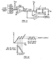
- FIG. 11 shows a circuit which can serve as a memory element in a 3-state logic system. Shown are source 91 of supply voltage V SS , source 92 of bias voltage V BA , input signal source 93, resistor 94, and output terminal 95. As illustrated in FIG. 12, the bias voltage V BA between the terminals A and B is adjusted to produce a current-voltage characteristic having essentially equal peaks at the same current level. And, for a suitable supply voltage V SS , and load resistance R L , the load line intersects the current-voltage characteristic at five different points of which three (Q1, Q2, and Q3) are in the positive slope parts of the curve and hence correspond to stable operating points.
- the circuit can stay indefinitely at any one of these points, thus retaining the last voltage information supplied.
- the device can be used as a memory element having three stable states, with voltages V1, V2, and V3 representing three logic values. (As compared with existing three-state logic circuits requiring 4 conventional transistors and 6 resistors, this represents a significantly simpler alternative.)
- the circuit can be switched from one state to another by applying a short voltage pulse.
- the three-state memory cell as discussed above in connection with FIG. 11 and FIG. 12 is well-suited for integration in memory integrated circuits with read-write and encoding capabilities as shown in FIG. 13.
- the memory cells are interconnected as a matrix array, and a particular element in the array is addressed by activating the corresponding row- and column-select lines.
- a row-select connects each device in a specified row to the corresponding column line, and the column-select connects the selected column to the data bus.
- the driving switch Q1 is turned on, as well as the switches for every element in the i-th row.
- the column-select logic now connects the j-th column to the data bus.
- the ternary identity cell T (described in detail, e.g., by A. Heung et al., "An all-CMOS Ternary Identity Cell for VLSI Implementation", Electronics Letters, Vol. 20 (1984), pp. 221-222) acts as buffer between the memory element and the external circuit.
- the identity cell For reading data from the memory, the identity cell is activated with the read-enable line, and data from the (i, j)-th element is transferred via the data bus to the I/O pin of the circuit.
- the write-enable line When the write-enable line is activated, data from an external circuit is connected to the data bus and written on the (i, j)-th element.
- FIG. 14 shows a circuit which can operate as a 4-bit parity generator, appreciation of corresponding device operation being facilitated by reference to FIG. 15 which shows the current-voltage characteristic of the device.
- the four digital input signals are added in the inverting summing amplifier A1 to produce five distinct voltage steps at its output, corresponding to the number of digital bits in the high state. Normally, the output of A1 would be negative for positive input voltages.
- the addition of a suitable negative offset voltage V OFF at the input results in up-shifting of the waveform to produce the output for A1 shown in the bottom part of FIG. 15.
- the substrate bias voltage V SS is adjusted to select the operating points of the device at the five points emphasized by dots in the current-voltage characteristic, corresponding, respectively, to the five voltage levels at the A1 output.
- the substrate current of the device generates a voltage across the 7.5-ohm resistor, which is picked up by the buffer amplifier A2.
- the circuit operates as a 4-bit parity generator in that its output is high when the number of input bits set high is odd, and low otherwise. As compared with a conventional circuit using 3 exclusive-OR gates, each requiring 8 transistors, considerable reduction in the number of circuit components is realized in the circuit of FIG. 14.
- circuits of FIG. 7, 11, 13, and 14 preferably involves the use of highly miniaturized resonant-tunneling devices
- relatively large-scale devices having dimensions as described with respect to FIG.1 are of immediate interest on account of low internal impedance of approximately 10 ohms, and further on account of compatibility with bipolar threshold detectors due to voltage steps of approximately 0.6 to 0.7 volts.
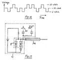
- a device as described can be used as a driver of the pseudo-ternary signal used in coaxial-cable telephone transmission; see FIG. 16 for a typical such signal stream as designed for easy extraction of the clock signal.
- FIG. 17 diagrammatically shows pseudo-ternary driver 71 for coaxial cable 72; driver 71 includes device 1 in accordance with FIG. 1.
- internal impedance of driver 71 is less than approximately one-tenth of the characteristic impedance of cable 72, the latter typically being in the range from 50 to 75 ohms.
- the driver is at the middle state (M-state). If an up-going pulse 73 is applied, the driver undergoes transition to the high state (H-state), and if then a down-going pulse 74 is applied, the driver returns to the middle state. With the driver at middle state, if a down-going pulse 74 is applied, the driver switches to the low state (L-state).
- a two-terminal device is of interest as exemplified by a device made by molecular-beam epitaxy processing as follows:
- n+ indium phosphide substrate On an n+ indium phosphide substrate a one-micrometer buffer layer was grown of n+ (approximately 3 x 10¹⁷/cm3) Ga 0.47 In 0.53 As, followed by a resonant-tunneling structure consisting of three 5-nanometer layers such as a first barrier layer of undoped Al 0.48 In 0.52 As, a quantum well layer of undoped Ga 0.47 In 0.53 As, and a second barrier layer of undoped Al 0.48 In 0.52 As. On the resonant-tunneling structure, a 1-micrometer cap layer of n+ (approximately 3 x 10¹⁷/cm3) Ga 0.47 In 0.53 As was deposited.
- a 50-micrometer mesa structure was formed by etching with 1 H2O2 + 3 H3PO4 + 50 H2O at room temperature, and a top ohmic contact having a diameter of 30 micrometers was made by sequential deposition of 6 nanometers germanium, 13.5 nanometers gold, 50 nanometers silver, and 75 nanometers gold, and alloying at a temperature of 420 degrees C for 30 seconds.
- a top ohmic contact having a diameter of 30 micrometers was made by sequential deposition of 6 nanometers germanium, 13.5 nanometers gold, 50 nanometers silver, and 75 nanometers gold, and alloying at a temperature of 420 degrees C for 30 seconds.
- For the bottom contact 5 nanometers nickel, 38.5 nanometers gold, 21.5 nanometers germanium, and 75 nanometers gold were deposited on the etched surface of the buffer layer and alloyed at a temperature of 420 degrees C for 30 seconds.
- Diode operation was tested at a temperature of 80 degrees K and at room temperature in a Helitran dewar equipped with microprobes. Resulting current-voltage characteristic are as shown in FIG. 18 and FIG. 19, respectively, bias voltage being defined as voltage of the top contact relative to the bottom contact.
- room-temperature operation exhibits a peak-to-valley ratio of 4 : 1 in one polarity, and 3.5 : 1 in the other. While the peak-to-valley ratio increases upon cooling of the device, peak current remains essentially constant (approximately 125 mA at 600 mV).
- a resonant-tunneling diode as described above is suitable for operation at temperatures greater than 100 degrees K and, in particular, at temperatures at or near room temperature.
- resonant-tunneling diodes are suitable for a variety of circuit applications.
- a circuit consisting of a voltage source, a resonant-tunneling diode, and a load resistor in series can serve as a bistable memory cell as may be implemented, e.g., by replacing device 1 in FIG. 13 by a resonant-tunneling diode.
- the diode as described above exhibits abrupt current drop. While this device aspect is desirable, e.g., for memory application, other device uses such as, e.g., analog applications may preferably be based on characteristics having a region of more gradual current transition.
- a device of this latter kind has been realized as follows: on the emitter side of the device, an essentially undoped layer is interposed between the contact and the first barrier layer to permit, during device operation, emitted carriers to be accelerated in the electric field in the undoped layer. As a result, carrier energy at the barrier can be described by a distribution as depicted in the diagram of FIG. 20, with a peak occurring at an energy substantially higher than the conduction band edge.
- preferred accelerator layer thickness is greater than or equal to 40 nanometers.
- Shown in FIG. 21 is the current-voltage characteristic of a corresponding device having the following spcific structure on an indium phosphide substrate: 500 nanometers N+ Ga 0.47 In 0.53 As, 5 nanometers undoped Al 0.48 In 0.52 As, 5 nanometers undoped Ga 0.47 In 0.53 As, 5 nanometers undoped Al 0.48 In 0.52 As, 200 nanometers undoped Ga 0.47 In 0.53 As, and 200 nanometers n+ Ga 0.47 In 0.53 As.
Abstract
Description
- The invention is concerned with apparatus including semiconductor devices whose operation is based on resonant tunneling through a quantum well.
- Concomitant to a continuing trend towards miniaturization and increased functional density in electronic devices, considerable attention has been paid to so-called resonant-tunneling devices as characterized by operation involving carrier energy coinciding with a quantized energy level in a potential well. After early theoretical work, resonant-tunneling devices have been implemented at least experimentally, and an extensive literature has come into existence concerning theoretical and practical device aspects as surveyed, e.g., by
F. Capasso et al., "Resonant Tunneling Through Double Barriers, Perpendicular Quantum Transport Phenomena in Superlattices, and Their Device Applications", IEEE Journal of Quantum Electronics, Vol. QE-22 (1986), pp. 1853-1869. - Resonant-tunneling devices can be made as diodes and as transistors; see, e.g.,
E. R. Brown el al., "Millimeter-band Oscillations Based on Resonant Tunneling in a Double-barrier Diode at Room Temperature", Applied Physics Letters, Vol. 50 (1987), pp. 83-85;
H. Toyoshima et al., "New Resonant Tunneling Diode with a Deep Quantum Well", Japanese Journal of Applied Physics, Vol. 25 (1986), pp. L786-L788;
H Morkoc et al., "Observation of a Negative Differential Resistance Due to Tunneling through a Single Barrier into a Quantum Well", Applied Physics Letters, Vol 49 (1986), pp. 70-72;
F. Capasson et al., "Resonant Tunneling Transistor with Quantum Well Base and High-energy Injection: A New Negative Differential Resistance Device", Journal of Applied Physics, Vol. 58 (1985), pp. 1366-1368;
N. Yokoyama et al., "A New Functional, Resonant-Tunneling Hot Electron Transistor (RHET)", Japanese Journal of Applied Physics, Vol. 24 (1985), pp. L853-L854;
F. Capasson et al., "Quantum-well Resonant Tunneling Bipolar Transistor Operating at Room Temperature", IEEE Electron Device Letters, Vol. EDL-7 (1986), pp. 573-575;
T. Futatsugi et al., "A Resonant-tunneling Bipolar Transistor (RBT): A Proposal and Demonstration for New Functional Devices with High Current Gains", Technical Digest of the 1986 International Electron Devices Meeting, pp. 286-289;
T. K. Woodward et al., "Experimental Realization of a Resonant Tunneling Transistor", Applied Physics Letters, Vol. 50 (1987), pp. 451-453;
B. Vinter et al., "Tunneling Transfer Field-effect Transistor: A Negative Transconductance Device", Applied Physics Letters, Vol 50 (1987), pp. l410-412;
A. R. Bonnefoi et al., "Inverted Base-collector Tunnel Transistors", Applied Physics Letters, Vol. 47 (1985), pp. 888-890;
S. Luryi et al., "Resonant Tunneling of Two-dimensional Electrons through a Quantum Wire: A Negative Transconductance Device", Applied Physics Letters, Vol. 47 (1985), pp. 1347-1693; and
S. Luryi et al., "Charge Injection Transistor Based on Real-Space Hot-Electron Transfer", IEEE Transactions on Electron Devices, Vol. ED-31 (1984), pp. 832-839. - Considered as of particular interest are devices having current-voltage characteristics including multiple negative resistance regions - this on account of potentially greatly reduced circuit complexity attendant to the use of such devices. However, while such multiple regions can be obtained from a plurality of resonances of a quantum well, resulting devices typically suffer from the drawback that current peaks corresponding to excited states carry significantly greater amounts of current as compared with the amount of current carried in the ground state.
- Apparatus in accordance with the invention such as, e.g., central processors and memory, switching systems, frequency multipliers, and waveform scramblers include a device which, under suitable operating conditions, has a plurality of negative resistance regions with equal or nearly equal peak currents, separation between the peaks being voltage tunable. Device operation is based on exclusive use of the ground-state resonance of a quantum well. The device includes a substrate-supported resonant-tunneling structure between terminals such that side-by-side first and third terminals are on one side, and a second terminal is on the opposite side of the resonant-tunneling structure.
- Included further are (two-terminal) resonant-tunneling diodes as incorporated in memory devices, e.g., in lieu of 2-transistor flip-flops; room-temperature device operation; and devices comprising an essentially undoped accelerator region between an emitter contact and a resonant-tunneling structure.
-
- FIG. 1 is a schematic cross-sectional representation of a preferred embodiment of a device in apparatus of the invention;
- FIG. 2 is a diagram of a circuit which is operationally equivalent to the device shown in FIG. 1;
- FIG. 3 is a schematic cross-sectional representation of a second preferred embodiment of a device in apparatus of the invention;
- FIG. 4 is a schematic cross-sectional representation of a third preferred embodiment of a device in apparatus of the invention;
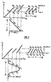
- FIG. 5 and 6 are photographically recorded current-voltage diagrams as obtained by operating a device as shown in FIG. 1;
- FIG. 7 is a diagram of first apparatus or circuit including a device in accordance with the invention;
- FIG. 8 and 9 are schematic current-voltage diagrams corresponding to operation of a circuit in accordance with FIG. 7, such circuit serving as a frequency multiplier;
- FIG. 10 is a photographically recorded current-voltage diagram corresponding to operation of the circuit shown in FIG. 7, operating conditions being chosen for waveform scrambling;
- FIG. 11 is a diagram of second apparatus or circuit including a device in accordance with the invention;
- FIG. 12 is a schematic current-voltage diagram corresponding to operation of the circuit shown in FIG. 11, such circuit serving as a three-state memory element;
- FIG. 13 is a diagram of a typical integrated circuit layout using a three-state memory element in accordance with the invention;
- FIG. 14 is a diagram of third apparatus or circuit including a device in accordance with the invention;
- FIG. 15 is a schematic current-voltage diagram corresponding to operation of the circuit shown in FIG. 14, such circuit serving as a parity-bit generator;
- Fig. 16 is a diagram of voltage levels representing binary signals in pseudo-ternary form as used in coaxial telephone systems;
- FIG. 17 is a diagram of fourth apparatus or circuit including a device in accordance with the invention, adapted for coaxial line driving;
- FIG. 18 is a current-voltage diagram of an InAlAs-InGaAs-InAlAs resonant-tunneling diode as operating at a temperature of 80 degrees K;
- FIG. 19 is a current-voltage diagram of an INAlAs-InGaAs-InAlAs resonant-tunneling diode as operating at room temperature;
- FIG. 20 is a diagram illustrating the effect of an accelerator region between emitter contact and resonant-tunneling structure; and
- FIG. 21 is a current-voltage diagram of a resonant-tunneling device comprising an accelerator region between emitter contact and resonant-tunneling structure.
- Representative device structure as shown in FIG. 1 may be made by standard molecular-beam-epitaxy processing starting with
gallium arsenide substrate 2 whose crystallographic orientation is (100), and which is doped n⁺ with silicon. Epitaxially deposited onsubstrate 2 is a galliumarsenide buffer layer 3 which is doped n⁺ with approximately 5x10¹⁷/cm³ silicon, and which has a thickness of approximately 1 micrometer. Further deposited are a nominally undopedgallium arsenide layer 4 having a thickness of approximately 250 nanometers, followed bylayers double barrier 18 including a quantum well.Barrier layers - On the double-
barrier structure 18, aheterojunction 19 is grown, preferably in the form of a modulation-doped aluminum gallium arsenide/gallium arsenide heterojunction consisting of a nominally undoped galliumarsenide channel layer 8 having a thickness of approximately 20 nanometers, a nominally undoped Al0.35Ga0.65Asspacer layer 9 having a thickness of approximately 8 nanometers, and an Al0.35Ga0.65Asdonor layer 10, doped n⁺ with approximately 2x10¹⁸/cm³ silicon, and having a thickness of approximately 40 nanometers.Channel layer 8 contains a high-mobility electron gas which has a density of approximately 10¹⁸/cm³, and which is spatially separated byspacer layer 9 from the parent donors in the aluminum galliumarsenide donor layer 10. - Use of a modulation-doped
heterojunction 19 as described above is in the interest of facilitating the formation of low-resistance ohmic contact to the heterojunction while keeping the dopants away from the double barrier. Also, the aluminum gallium arsenide oflayer 9 serves to passivate the adjacent galliumarsenide channel layer 8. - After deposition of gallium
arsenide contact layer 11, doped n⁺ with approximately 2x10¹⁷/cm³ silicon and having a thickness of approximately 140 nanometers,metallization layer 12 is formed by evaporation, onlayer 11 in the presence of a lift-off mask, and also onsubstrate 2. Conveniently, germanium (12 nanometers), gold (27 nanometers), silver (100 nanometers), and gold (150 nanometers) are evaporated in succession, and two contact pads A and B are made approximately 240 micrometers long and 80 micrometers wide, situated side-by-side, with long sides adjacent and separated by a distance of approximately 6.5 micrometers. Heat treatment for 10 seconds at a temperature of 380 degrees C is suitable for alloying of the metallization, and the alloyed metallization can further serve as a mask for wet chemical etching oflayer 11 to exposelayer 10, e.g., by means of a selective stop etch of hydrogen peroxide and ammonium hydroxide, with pH approximately 7.2. - While molecular-beam epitaxy is considered as well-suited and convenient for device fabrication, the use of other deposition methods is not precluded. For example, sufficient accuracy in layer composition and thickness may be achievable in liquid-phase epitaxy (LPE) and in atomic-layer epitaxy (ALE). Also, while the material system GaAs/AlAs is convenient for device implementation, other material combinations can be used as selected, e.g., from the systems InGaAs/InAlAs, InGaAsP/InP, and GaAs/AlGaAs, lattice-matched to suitable gallium-arsenide or indium-phosphide substrates.
- With reference to FIG. 2, a device as shown in FIG. 1 can be understood in functional terms as being equivalent to two resonant-
tunneling diodes 21 and 22 in parallel, withresistor 23 connection the diodes as corresponding to the portion ofchannel layer 8 extending the length of the gap between contact pads A and B of FIG. 1. (In the device as specifically described above, the resistance of this portion as measured between contacts A and B was found to be approximately 12 ohms.) Terminals A and B, as well as substrate terminal S shown in FIG. 2 are in correspondence with contact pads of FIG. 1. - During device operation, resonant tunneling current flows from the substrate through the double barrier into the channel layer, and such current flows under the contact pads as well as in the region between the pads. Preferably, pads A and B have approximately the same area and, for current under the pads to be large, pad area is preferably chosen to significantly exceed the area between pads. Alternatively, as shown in FIG. 3, layer portions of some or all of
layers 3 to 10 of FIG. 1 may be etched away between contacts, leaving, e.g., resonant-tunneling diode structures 31 mutually isolated as may be advantageous in the interest of minimization of background current. Furthermore, etching after layer deposition may be used to produce, on one and the same substrate, a plurality of devices in accordance with FIG. 1. - As a further variant form of the device, depicted in FIG. 4, one or several additional contact pads may be provided between pads A and B of FIG. 1, and it is apparent that such provision is functionally equivalent to the presence in FIG. 2 of more than two resonant-tunneling diodes in parallel. In this case, the resistance of portions of
layer 8 extending between contact pads conveniently provides for voltage division, thereby obviating the need for additional voltage sources. (In the interest of approximately constant voltage division, design of the structure preferably provides for sufficiently large current in the divider network as compared with current through the resonant-tunneling diodes.) - Further with reference to FIG. 1, device operation equivalent to side-by-side resonant-tunneling diodes can be realized also in the absence of
heterojunction 19, in which case an offset layer may be used replacingheterojunction 19; for example, a 5-nanometer layer of undoped gallium arsenide is suitable for this purpose. - While it is possible to implement the circuit of FIG. 2 using
discrete tunnel diodes 21 and 22, a monolithically integrated device has distinct advantages in that, e.g., parasitic resistances and capacitances are reduced, and in that the reproducibility of current-voltage characteristics is enhanced due to uniformity of doping levels in the two or more resonant-tunneling diodes made on a common substrate in the course of one and the same manufacturing process. - For different values of the potential difference VBA between terminals B and A of FIG. 1, current through substrate terminal S of a device as described above was measured as a function of a positive bias applied between terminal S and grounded terminal A; this current is essentially the sum of the two resonant-tunneling currents flowing through the two resonant-tunneling diodes. As is apparent upon inspection of the corresponding graphs (FIG. 5 and FIG. 6), for zero potential difference VBA there is a single current peak, negative conductance being due to quenching of resonant tunneling through the double barriers under terminals A and B. When terminal B is biased negatively with respect to terminal A (FIG. 5), an additional current peak develops at lower voltages; the position of one peak remains unchanged while that of the other moves to lower bias as the potential difference VBA between B and A is made more negative. By appropriate choice of the bias between B and A the two peak currents can be made nearly equal.
- An explanation of this effect may be provided as follows: As a result of the bias applied between A and B, the potential differences across the two double barriers are different, and for B negatively biased with respect to A, resonant tunneling through the double barrier under teminal B is quenched at a lower substrate bias than in the double barrier under terminal A, leading to two peaks in the current-voltage diagram. The peak that does not shift with varying VBA is associated with quenching of resonant tunneling through the diode under terminal A. As expected, the separation between the peaks is nearly equal to the bias applied between A and B.
- Finally, if terminal B is positively biased with respect to terminal A (FIG. 6), a higher voltage is required to quench resonant tunneling through the double barrier under terminal B, leading to a second peak which shifts to higher voltages as VBA is increased. Similar results are obtained with negative bias applied to terminal S.
- While the characteristics of FIG. 5 and 6 were obtained for an operating temperature of 100 K, suitable processing and material choices are expected to permit room-temperature device operation as have been realized in resonant-tunneling diodes and transistors
- The device of FIG. 1 can be used in suitably designed circuitry for a variety of functions; one circuit, designed for frequency multiplication, is shown in FIG. 7 with associated current-voltage diagrams of FIG. 8 and FIG. 9, bias voltage VBA between terminal A and B of the device being fixed.
- FIG. 7 shows
device 1 with terminals A, B, and S in accordance with FIG. 1,source 51 of substrate bias voltage VSS,source 52 of bias voltage VBA,input signal source 53,resistor 54, andoutput terminals 55. - FIG. 8 shows device characteristics in the case of a sawtooth input voltage, substrate bias voltage VSS having been adjusted to select the quiescent operating point A₂. As the sawtooth input voltage increases from A₁ to B₁, the operating point shifts from A₂ to B₂ along the characteristic, with the substrate current Is increasing approximately linearly. The output voltage across the resistance R is proportional to the source current Is, and thus its increase from A₃ to B₃ is also approximately linear. As the input voltage increases beyond B₁, the source current Is suddenly drops to the valley point B₂′, resulting in a sudden drop in the output voltage from B₃ to B₃′. Between B₃ and C₃, the output continues to rise again, followed by a second drop at C₂, and then a rise as the input continues to rise up to D₁. At D₁, the input returns to zero to start a new cycle, and the operating point also shifts back to A₂, with a drop in the output as well. Accordingly, the frequency of the sawtooth input signal has been multiplied by a factor of 3. (If VBA had been adjusted to produce a single peak in the current-voltage diagram, sawtooth frequency would have been multiplied by a factor of two.)
- FIG. 9 illustrates device operation in case of a sine-wave input and is amenable to detailed description analogous to description in the case of FIG. 8 above. The output waveform is found to be rich in the fifth harmonic of the input. (If VBA had been adjusted to produce a single peak in the current-voltage diagram, the output would have been rich in the third harmonic.)
- Experimental results obtained with VBA=1V and VSS=2.3V in the circuit of FIG. 7 showed superior efficiency in frequency multiplication and in generating fifth harmonic as compared with conventional devices such as, e.g., a step recovery diode.
- FIG. 10 shows output of a circuit of FIG. 7 used for waveform scrambling in the case of a sine-wave input signal. Scrambling is effected by choosing a bias VBA such that the two current peaks are of different height (here, specifically, VBA=1.4V) in which case the input waveform is broken up at arbitrary phases, and the different segments are amplified differently at the output. The original waveform can be recovered from the scrambled signal by using an identical device in the feedback circuit of an amplifier, biased to the same voltages as in the scrambling circuit.
- FIG. 11 shows a circuit which can serve as a memory element in a 3-state logic system. Shown are source 91 of supply voltage VSS, source 92 of bias voltage VBA, input signal source 93,
resistor 94, and output terminal 95. As illustrated in FIG. 12, the bias voltage VBA between the terminals A and B is adjusted to produce a current-voltage characteristic having essentially equal peaks at the same current level. And, for a suitable supply voltage VSS, and load resistance RL, the load line intersects the current-voltage characteristic at five different points of which three (Q₁, Q₂, and Q₃) are in the positive slope parts of the curve and hence correspond to stable operating points. Corresponding to these stable operating points there are respective output voltages V₁, V₂, and V₃, and the circuit can stay indefinitely at any one of these points, thus retaining the last voltage information supplied. Thus, the device can be used as a memory element having three stable states, with voltages V₁, V₂, and V₃ representing three logic values. (As compared with existing three-state logic circuits requiring 4 conventional transistors and 6 resistors, this represents a significantly simpler alternative.) The circuit can be switched from one state to another by applying a short voltage pulse. - In an experiment, switching between states was effected by momentarily changing the supply voltage VSS which is equivalent to applying a short voltage pulse. With a supply voltage VSS=16V, a load resistance RL=215 ohms, and a bias voltage VBA=0.7V, the three stable states were found to be at 3.0V, 3.6V, and 4.3V. The corresponding load line as drawn on the measured current-voltage characteristics of the device intersects, respectively, at 2.8V, 3.4V, and 4.1V, in close agreement with the measured values of the operating points.
- The three-state memory cell as discussed above in connection with FIG. 11 and FIG. 12 is well-suited for integration in memory integrated circuits with read-write and encoding capabilities as shown in FIG. 13. the memory cells are interconnected as a matrix array, and a particular element in the array is addressed by activating the corresponding row- and column-select lines. A row-select connects each device in a specified row to the corresponding column line, and the column-select connects the selected column to the data bus. For example, in the case of the (i, j)-element shown in FIG. 13 when the i-th row-select line is activated, the driving switch Q1 is turned on, as well as the switches for every element in the i-th row. The column-select logic now connects the j-th column to the data bus. The ternary identity cell T (described in detail, e.g., by A. Heung et al., "An all-CMOS Ternary Identity Cell for VLSI Implementation", Electronics Letters, Vol. 20 (1984), pp. 221-222) acts as buffer between the memory element and the external circuit. For reading data from the memory, the identity cell is activated with the read-enable line, and data from the (i, j)-th element is transferred via the data bus to the I/O pin of the circuit. When the write-enable line is activated, data from an external circuit is connected to the data bus and written on the (i, j)-th element.
- FIG. 14 shows a circuit which can operate as a 4-bit parity generator, appreciation of corresponding device operation being facilitated by reference to FIG. 15 which shows the current-voltage characteristic of the device. The four digital input signals are added in the inverting summing amplifier A₁ to produce five distinct voltage steps at its output, corresponding to the number of digital bits in the high state. Normally, the output of A₁ would be negative for positive input voltages. The addition of a suitable negative offset voltage VOFF at the input results in up-shifting of the waveform to produce the output for A₁ shown in the bottom part of FIG. 15. The substrate bias voltage VSS is adjusted to select the operating points of the device at the five points emphasized by dots in the current-voltage characteristic, corresponding, respectively, to the five voltage levels at the A₁ output. The substrate current of the device generates a voltage across the 7.5-ohm resistor, which is picked up by the buffer amplifier A₂. The circuit operates as a 4-bit parity generator in that its output is high when the number of input bits set high is odd, and low otherwise. As compared with a conventional circuit using 3 exclusive-OR gates, each requiring 8 transistors, considerable reduction in the number of circuit components is realized in the circuit of FIG. 14.
- While implementation of circuits of FIG. 7, 11, 13, and 14 preferably involves the use of highly miniaturized resonant-tunneling devices, relatively large-scale devices having dimensions as described with respect to FIG.1 are of immediate interest on account of low internal impedance of approximately 10 ohms, and further on account of compatibility with bipolar threshold detectors due to voltage steps of approximately 0.6 to 0.7 volts. In view of such impedance and voltage characteristics, a device as described can be used as a driver of the pseudo-ternary signal used in coaxial-cable telephone transmission; see FIG. 16 for a typical such signal stream as designed for easy extraction of the clock signal.
- FIG. 17 diagrammatically shows
pseudo-ternary driver 71 forcoaxial cable 72;driver 71 includesdevice 1 in accordance with FIG. 1. Preferably, internal impedance ofdriver 71, as observed fromcable 72, is less than approximately one-tenth of the characteristic impedance ofcable 72, the latter typically being in the range from 50 to 75 ohms. Normally, the driver is at the middle state (M-state). If an up-goingpulse 73 is applied, the driver undergoes transition to the high state (H-state), and if then a down-going pulse 74 is applied, the driver returns to the middle state. With the driver at middle state, if a down-going pulse 74 is applied, the driver switches to the low state (L-state). - Among advantages of a driver as described are fast switching speed and small current spike as there is no overlapped drive due to signal skew.
- As the three-terminal device described above is operationally equivalent to a circuit comprising resonant-tunneling diodes in parallel, attention may be directed to resonant-tunneling diodes individually, i.e., as two-terminal devices. Moreover, as also stated above, room-temperature operation of (two-or multi-terminal) devices is desirable. In these respects, and further to the device described above, a two-terminal device is of interest as exemplified by a device made by molecular-beam epitaxy processing as follows:
- On an n⁺ indium phosphide substrate a one-micrometer buffer layer was grown of n⁺ (approximately 3 x 10¹⁷/cm³) Ga0.47In0.53As, followed by a resonant-tunneling structure consisting of three 5-nanometer layers such as a first barrier layer of undoped Al0.48In0.52As, a quantum well layer of undoped Ga0.47In0.53As, and a second barrier layer of undoped Al0.48In0.52As. On the resonant-tunneling structure, a 1-micrometer cap layer of n⁺ (approximately 3 x 10¹⁷/cm³) Ga0.47In0.53As was deposited.
- A 50-micrometer mesa structure was formed by etching with 1 H₂O₂ + 3 H₃PO₄ + 50 H₂O at room temperature, and a top ohmic contact having a diameter of 30 micrometers was made by sequential deposition of 6 nanometers germanium, 13.5 nanometers gold, 50 nanometers silver, and 75 nanometers gold, and alloying at a temperature of 420 degrees C for 30 seconds. For the bottom contact, 5 nanometers nickel, 38.5 nanometers gold, 21.5 nanometers germanium, and 75 nanometers gold were deposited on the etched surface of the buffer layer and alloyed at a temperature of 420 degrees C for 30 seconds.
- Diode operation was tested at a temperature of 80 degrees K and at room temperature in a Helitran dewar equipped with microprobes. Resulting current-voltage characteristic are as shown in FIG. 18 and FIG. 19, respectively, bias voltage being defined as voltage of the top contact relative to the bottom contact. As can be seen from FIG. 19, room-temperature operation exhibits a peak-to-valley ratio of 4 : 1 in one polarity, and 3.5 : 1 in the other. While the peak-to-valley ratio increases upon cooling of the device, peak current remains essentially constant (approximately 125 mA at 600 mV).
- An electron-tunneling-transmission calculation shows that the first resonance is at E₁ = 126 meV from the bottom of the quantum well. Appearance of the peak in the current-voltage characteristic at a voltage greater than 2 E₁/e = 252 mV may be explained by consideration of the voltage drop in the depletion and accumulation regions in the collector and emitter layers adjacent to the double-barrier. Thus, to line up the first sub-band in the well with the bottom of the conduction band in the emitter (and thus to quench resonant tunneling), a larger voltage is required across the entire structure. On account of large peak-to-valley ratio as observed at operating temperatures higher than those previously employed, a resonant-tunneling diode as described above is suitable for operation at temperatures greater than 100 degrees K and, in particular, at temperatures at or near room temperature.
- On account of bistability, resonant-tunneling diodes are suitable for a variety of circuit applications. For example, a circuit consisting of a voltage source, a resonant-tunneling diode, and a load resistor in series can serve as a bistable memory cell as may be implemented, e.g., by replacing
device 1 in FIG. 13 by a resonant-tunneling diode. (The above-described resonant-tunneling diode, in series with a 30-ohm load resistor and a 3-volt power supply, was found to have room-temperature operating points at 0.47 V and 0.85 V.) Due to the greater simplicity of resonant-tunneling diode cells as compared with conventional, 2-transistor flip-flop circuit cells, integration of resonant-tunneling diode cells into memory arrays may require fewer interconnections. - As can be seen from FIG. 18 and 19, the diode as described above exhibits abrupt current drop. While this device aspect is desirable, e.g., for memory application, other device uses such as, e.g., analog applications may preferably be based on characteristics having a region of more gradual current transition. A device of this latter kind has been realized as follows: on the emitter side of the device, an essentially undoped layer is interposed between the contact and the first barrier layer to permit, during device operation, emitted carriers to be accelerated in the electric field in the undoped layer. As a result, carrier energy at the barrier can be described by a distribution as depicted in the diagram of FIG. 20, with a peak occurring at an energy substantially higher than the conduction band edge. Depending on bias voltage, carriers to either side of the energy peak are available for resonant tunneling; as a result, instead of abrupt quenching, the resonant-tunneling current drops gradually beyond the peak voltage. In the interest of an appreciable effect, preferred accelerator layer thickness is greater than or equal to 40 nanometers.
- Shown in FIG. 21 is the current-voltage characteristic of a corresponding device having the following spcific structure on an indium phosphide substrate: 500 nanometers N⁺ Ga0.47In0.53As, 5 nanometers undoped Al0.48In0.52As, 5 nanometers undoped Ga0.47In0.53As, 5 nanometers undoped Al0.48In0.52As, 200 nanometers undoped Ga0.47In0.53As, and 200 nanometers n⁺ Ga0.47In0.53As.
Claims (3)
Applications Claiming Priority (2)
| Application Number | Priority Date | Filing Date | Title |
|---|---|---|---|
| US117583 | 1987-11-05 | ||
| US07/117,583 US4853753A (en) | 1987-07-01 | 1987-11-05 | Resonant-tunneling device, and mode of device operation |
Publications (2)
| Publication Number | Publication Date |
|---|---|
| EP0320110A2 true EP0320110A2 (en) | 1989-06-14 |
| EP0320110A3 EP0320110A3 (en) | 1990-05-09 |
Family
ID=22373703
Family Applications (1)
| Application Number | Title | Priority Date | Filing Date |
|---|---|---|---|
| EP88310336A Ceased EP0320110A3 (en) | 1987-11-05 | 1988-11-03 | Memory device comprising a resonant-tunneling semiconductor diode and mode of operation |
Country Status (5)
| Country | Link |
|---|---|
| US (1) | US4853753A (en) |
| EP (1) | EP0320110A3 (en) |
| JP (1) | JPH023142A (en) |
| KR (1) | KR930002817B1 (en) |
| CA (1) | CA1282871C (en) |
Cited By (2)
| Publication number | Priority date | Publication date | Assignee | Title |
|---|---|---|---|---|
| EP0297778A2 (en) * | 1987-07-01 | 1989-01-04 | AT&T Corp. | Apparatus including resonant-tunneling device having multiple-peak current-voltage characteristics |
| EP0708487A1 (en) * | 1994-10-20 | 1996-04-24 | Hitachi Europe Limited | Memory device |
Families Citing this family (13)
| Publication number | Priority date | Publication date | Assignee | Title |
|---|---|---|---|---|
| US4926232A (en) * | 1987-09-02 | 1990-05-15 | Nec Corporation | Resonant-tunneling bipolar transistor |
| US5012301A (en) * | 1990-02-22 | 1991-04-30 | Northern Telecom Limited | Three terminal semiconductor device |
| US4999687A (en) * | 1990-04-25 | 1991-03-12 | At&T Bell Laboratories | Logic element and article comprising the element |
| US5128894A (en) * | 1990-09-28 | 1992-07-07 | University Of Maryland | Multi-value memory cell using resonant tunnelling diodes |
| US5126553A (en) * | 1990-11-28 | 1992-06-30 | Bell Communications Research, Inc. | Bistable optically switchable resonant-tunneling device and its use in signal processing |
| US5347140A (en) * | 1991-08-27 | 1994-09-13 | Matsushita Electric Industrial Co., Ltd. | Resonant electron transfer device |
| US5237596A (en) * | 1991-10-08 | 1993-08-17 | University Of Maryland | Stepping counter using resonant tunneling diodes |
| JP3542620B2 (en) * | 1992-09-30 | 2004-07-14 | テキサス インスツルメンツ インコーポレイテツド | Multi-peak resonant tunneling diode |
| US5408107A (en) * | 1993-05-20 | 1995-04-18 | The Board Of Regents Of The University Of Texas System | Semiconductor device apparatus having multiple current-voltage curves and zero-bias memory |
| US5539214A (en) * | 1995-02-06 | 1996-07-23 | Regents Of The University Of California | Quantum bridges fabricated by selective etching of superlattice structures |
| JP2001077352A (en) * | 1999-09-07 | 2001-03-23 | Sony Corp | Semiconductor device and its manufacturing method |
| US8368380B2 (en) * | 2010-03-31 | 2013-02-05 | General Electric Company | Devices and methods for electric field sensing |
| US8604772B2 (en) * | 2010-03-31 | 2013-12-10 | General Electric Company | MEMS-based resonant tunneling devices and arrays of such devices for electric field sensing |
Citations (1)
| Publication number | Priority date | Publication date | Assignee | Title |
|---|---|---|---|---|
| JPS6150359A (en) * | 1984-08-20 | 1986-03-12 | Fujitsu Ltd | Semiconductor memory device |
Family Cites Families (4)
| Publication number | Priority date | Publication date | Assignee | Title |
|---|---|---|---|---|
| GB984222A (en) * | 1961-04-13 | 1965-02-24 | Nat Res Dev | Negative resistance diode storage circuits |
| US4410902A (en) * | 1981-03-23 | 1983-10-18 | The United States Of America As Represented By The Secretary Of The Army | Planar doped barrier semiconductor device |
| JPS61161774A (en) * | 1985-01-10 | 1986-07-22 | Nec Corp | Diode |
| US4667211A (en) * | 1985-09-05 | 1987-05-19 | The United States Of America As Represented By The Secretary Of The Army | Millimeter wave-infrared bloch oscillator/detector |
-
1987
- 1987-11-05 US US07/117,583 patent/US4853753A/en not_active Expired - Fee Related
-
1988
- 1988-11-02 KR KR1019880014355A patent/KR930002817B1/en not_active IP Right Cessation
- 1988-11-03 EP EP88310336A patent/EP0320110A3/en not_active Ceased
- 1988-11-04 CA CA000582271A patent/CA1282871C/en not_active Expired - Fee Related
- 1988-11-04 JP JP63277613A patent/JPH023142A/en active Pending
Patent Citations (1)
| Publication number | Priority date | Publication date | Assignee | Title |
|---|---|---|---|---|
| JPS6150359A (en) * | 1984-08-20 | 1986-03-12 | Fujitsu Ltd | Semiconductor memory device |
Non-Patent Citations (2)
| Title |
|---|
| IEEE ELECTRON DEVICE LETTERS, EDL-8, no. 7, July 1987, pages 297-299, New York, (US) F. CAPASSO et al.: "Resonant tunneling devices with multiple negative differential resistance and demonstration of a three-state memory cell for multiple-valued logic applications" * |
| PATENT ABSTRACTS OF JAPAN, vol. 10, no. 209, p. 2265, E-421, July 22, 1986; & JP-A-61 050 359 (FUJITSU LTD) 12-03-1986 * |
Cited By (5)
| Publication number | Priority date | Publication date | Assignee | Title |
|---|---|---|---|---|
| EP0297778A2 (en) * | 1987-07-01 | 1989-01-04 | AT&T Corp. | Apparatus including resonant-tunneling device having multiple-peak current-voltage characteristics |
| EP0297778A3 (en) * | 1987-07-01 | 1991-04-03 | AT&T Corp. | Apparatus including resonant-tunneling device having multiple-peak current-voltage characteristics |
| EP0708487A1 (en) * | 1994-10-20 | 1996-04-24 | Hitachi Europe Limited | Memory device |
| US5811832A (en) * | 1994-10-20 | 1998-09-22 | Hitachi, Ltd. | Non-volatile memory device |
| US6194303B1 (en) | 1994-10-20 | 2001-02-27 | Hitachi, Ltd. | Memory device |
Also Published As
| Publication number | Publication date |
|---|---|
| KR930002817B1 (en) | 1993-04-10 |
| KR890009006A (en) | 1989-07-13 |
| CA1282871C (en) | 1991-04-09 |
| US4853753A (en) | 1989-08-01 |
| JPH023142A (en) | 1990-01-08 |
| EP0320110A3 (en) | 1990-05-09 |
Similar Documents
| Publication | Publication Date | Title |
|---|---|---|
| Capasso et al. | Quantum functional devices: resonant-tunneling transistors, circuits with reduced complexity, and multiple valued logic | |
| Sen et al. | Resonant tunneling device with multiple negative differential resistance: digital and signal processing applications with reduced circuit complexity | |
| US5151618A (en) | Resonant-tunneling heterojunction bipolar transistor device | |
| US4902912A (en) | Apparatus including resonant-tunneling device having multiple-peak current-voltage characteristics | |
| US5021841A (en) | Semiconductor device with controlled negative differential resistance characteristic | |
| US4853753A (en) | Resonant-tunneling device, and mode of device operation | |
| Capasso et al. | Resonant tunneling devices with multiple negative differential resistance and demonstration of a three-state memory cell for multiple-valued logic applications | |
| US5023836A (en) | Semiconductor memory device | |
| CA1276275C (en) | Resonant tunneling transistor | |
| JPH02231777A (en) | Resonance tunnel optoelectronic device | |
| EP0279587A2 (en) | Comparator circuit | |
| US6303941B1 (en) | Integrated asymmetric resonant tunneling diode pair circuit | |
| US4999697A (en) | Sequential-quenching resonant-tunneling transistor | |
| JP2746771B2 (en) | Semiconductor device | |
| US4182965A (en) | Semiconductor device having two intersecting sub-diodes and transistor-like properties | |
| EP0297778A2 (en) | Apparatus including resonant-tunneling device having multiple-peak current-voltage characteristics | |
| Woodward et al. | Applications of resonant-tunneling field-effect transistors | |
| EP0363238A2 (en) | Semiconductor quantum effect device having negative differential resistance characteristics | |
| Beresford et al. | Resonant interband tunneling device with multiple negative differential resistance regions | |
| EP0698925A2 (en) | Bipolar transistor with floating base | |
| Baba et al. | Multiple-junction surface tunnel transistors for multiple-valued logic circuits | |
| CHO | AND ALFRED zyxwvutsrqponmlkjih | |
| Capasso et al. | Quantum transistors and circuits break through the barriers | |
| Tehrani et al. | Three terminal quantum structure based on resonant interband tunneling | |
| Beltram et al. | Photonic and Electronic Devices Based on Artificially Structured Semiconductors |
Legal Events
| Date | Code | Title | Description |
|---|---|---|---|
| PUAI | Public reference made under article 153(3) epc to a published international application that has entered the european phase |
Free format text: ORIGINAL CODE: 0009012 |
|
| AK | Designated contracting states |
Kind code of ref document: A2 Designated state(s): DE ES FR GB NL |
|
| PUAL | Search report despatched |
Free format text: ORIGINAL CODE: 0009013 |
|
| AK | Designated contracting states |
Kind code of ref document: A3 Designated state(s): DE ES FR GB NL |
|
| 17P | Request for examination filed |
Effective date: 19901030 |
|
| 17Q | First examination report despatched |
Effective date: 19920721 |
|
| STAA | Information on the status of an ep patent application or granted ep patent |
Free format text: STATUS: THE APPLICATION HAS BEEN REFUSED |
|
| RAP3 | Party data changed (applicant data changed or rights of an application transferred) |
Owner name: AT&T CORP. |
|
| 18R | Application refused |
Effective date: 19940218 |