EP0318668B1 - Siren detector - Google Patents
Siren detector Download PDFInfo
- Publication number
- EP0318668B1 EP0318668B1 EP88116287A EP88116287A EP0318668B1 EP 0318668 B1 EP0318668 B1 EP 0318668B1 EP 88116287 A EP88116287 A EP 88116287A EP 88116287 A EP88116287 A EP 88116287A EP 0318668 B1 EP0318668 B1 EP 0318668B1
- Authority
- EP
- European Patent Office
- Prior art keywords
- signal
- siren
- detector
- output
- red light
- Prior art date
- Legal status (The legal status is an assumption and is not a legal conclusion. Google has not performed a legal analysis and makes no representation as to the accuracy of the status listed.)
- Expired - Lifetime
Links
- 238000001514 detection method Methods 0.000 claims description 16
- 230000004044 response Effects 0.000 claims description 15
- 238000001914 filtration Methods 0.000 claims description 14
- 230000035945 sensitivity Effects 0.000 claims description 7
- 230000003213 activating effect Effects 0.000 claims description 3
- 239000003990 capacitor Substances 0.000 description 20
- 241000269400 Sirenidae Species 0.000 description 13
- 238000010586 diagram Methods 0.000 description 4
- 230000003111 delayed effect Effects 0.000 description 3
- 238000013459 approach Methods 0.000 description 2
- 238000000034 method Methods 0.000 description 2
- 230000001960 triggered effect Effects 0.000 description 2
- 230000000007 visual effect Effects 0.000 description 2
- 230000004075 alteration Effects 0.000 description 1
- 238000010276 construction Methods 0.000 description 1
- 125000004122 cyclic group Chemical group 0.000 description 1
- 230000030808 detection of mechanical stimulus involved in sensory perception of sound Effects 0.000 description 1
- 230000009977 dual effect Effects 0.000 description 1
- 230000036039 immunity Effects 0.000 description 1
- 238000012986 modification Methods 0.000 description 1
- 230000004048 modification Effects 0.000 description 1
- 238000012544 monitoring process Methods 0.000 description 1
- 230000010255 response to auditory stimulus Effects 0.000 description 1
- 102220065736 rs543286136 Human genes 0.000 description 1
- 238000007493 shaping process Methods 0.000 description 1
- 230000002459 sustained effect Effects 0.000 description 1
- 230000036962 time dependent Effects 0.000 description 1
Images


Classifications
-
- G—PHYSICS
- G08—SIGNALLING
- G08G—TRAFFIC CONTROL SYSTEMS
- G08G1/00—Traffic control systems for road vehicles
- G08G1/07—Controlling traffic signals
- G08G1/087—Override of traffic control, e.g. by signal transmitted by an emergency vehicle
Definitions
- This application pertains to a siren detector for detecting siren sounds which precess within a selected frequency band.
- the detector facilitates pre-emptable control of traffic lights to enable the vehicle to pass through a traffic intersection on a priority basis.
- a sound detection sensing and selective monitoring system is known in the art from EP-A-0 091 276.
- This publication discloses a sound detection system comprising a sound detector to produce sound detected signals, means for shaping and amplifying as well as clipping these signals, a low pass filter cutoff to truncate high frequency signals due to noise and other unwanted sources, and a parallel system of four band pass filters with center frequencies at 800 Hz, 1000 Hz, 1200 Hz and 1400 Hz.
- the signals passed by the parallel array of band pass filters are time-analyzed to produce information intended to recognize time-dependent frequency changes in the original signal.
- US patent US 3,992,656 discloses an audio range siren detector utilizing an automatic gain control amplifier and a plurality of active filters having closely spaced resonant frequencies, the outputs of the filters being time-analyzed to produce information denoting a valid siren signal and relay means for setting traffic lights to emergency conditions.
- the prior art has evolved various ways of controlling or "pre-empting" vehicle traffic light to stop traffic at an intersection so that an emergency vehicle may pass unimpeded through the intersection on a priority basis.
- One technique involves the placement of a special transmitter in each emergency vehicle which is to be allowed priority passage through intersections.
- the traffic light controllers at each pre-emptable intersection are equipped with a receiver which receives signals transmitted by the transmitter and thereupon actuates the traffic lights to stop the normal flow of traffic.
- this technique is relatively expensive and is cumbersome in that personnel in the emergency vehicle must manually actuate the transmitter in order to control the traffic lights.
- Traffic light controllers at pre-emptable intersections have also been equipped with detectors capable of detecting flashing lights (normally special strobe lights) mounted on each emergency vehicle which is to be allowed priority passage through the pre-emptable intersections.
- this is similar to the system mentioned in the preceding paragraph, in that the emergency vehicle light replaces the special transmitter.
- the system does however enjoy something of a cost and utility advantage over the system mentioned in the preceding paragraph, since emergency vehicles are normally equipped with flashing lights which are actuated in emergency situations.
- the cost advantage diminishes if special lights must be provided in order to actuate the detector circuitry which interfaces with the traffic signal controller.
- the prior art has evolved a number of circuits for detecting siren sounds. However, the inventors consider these to be problematic in that they are susceptible to false alarm triggering by sounds emanating from sources other than emergency vehicle sirens.
- the present invention provides a siren detector for detecting siren sounds within a selected frequency band and having superior immunity to false alarm triggering by sounds emanating from sources other than emergency vehicle sirens.
- the invention provides a siren detector for detecting siren sounds which precess at known wail and yelp warble rates within a selected frequency band, said detector comprising transducer means for detecting said sounds and for producing an electrical output signal representative thereof, first filter means for filtering said signal to reject signal frequencies outside said selected band, and signal amplitude control means for varying the gain of said filtered signals to produce a constant amplitude output signal, second filter means for filtering said constant amplitude output signal and for converting said signal into a voltage, fourth filter means for filtering said voltage for detection therein of signals which vary at said yelp rate and for producing a yelp rate signal in response thereto, whereby said signal amplitude control means is adapted to limit and monitor the amplitude of filtered signals output by said first filter means, said second filter means comprises low pass filter means tuned to a mean frequency of the siren sweep frequency range and detector means to convert the signal output of said low pass filter means into a varying D.C. voltage, and third filter means are
- the siren detector is also capable of detecting siren sounds which precess between known frequencies at a known high-low warble rate.
- the detector may further comprise a fifth filter means for low pass filtering the aforementioned constant amplitude output signal for detection therein of signals characteristic of a low frequency component of a siren high-low sound; and, sixth filter means for further low pass filtering the constant amplitude output signal for detection therein of signals which vary at the high-low warble rate and for producing a high-low rate signal in response thereto.
- Don't walk clock means are provided for producing a don't walk timing signal in synchronization with the wail rate signal output by the third filter means; and, yelp clock means are provided for producing a red light timing signal in synchronization with the yelp rate signal output by the fourth filter means. If the siren detector has high-low sound detection capability as aforesaid, then the don't walk timing signal is also produced in synchronization with the high-low rate signal output by the sixth filter means.
- a seventh filter means is provided for delaying the red light timing signal to produce a gate signal for synchronization of the red light timing signal within the period of the yelp rate signal.
- a sensitivity selector means may be provided for adjusting the sensitivity of the siren detector to reject sounds below a selected threshold intensity level.
- Preempt control means are provided for activating the siren detector as the siren sounds increase in intensity and for deactivating the siren detector as those sounds fade.
- Don't walk output means controllable by the don't walk clock means and by the preempt control means are also provided.
- the don't walk output means is for producing a don't walk preempt output signal in response to the don't walk timing signal while the preempt control means activates the detector.
- a red light output means is similarly provided.
- the red light output means is controllable by the yelp clock means and also by the preempt control means.
- the red light output means is for producing a red light preempt signal in response to the red light timing signal while the preempt control means activates the detector.
- Figure 1 is a block diagram illustrating the basic operation of a siren detector according to the invention.
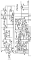
- Figure 2 is an electronic circuit schematic diagram of a siren detector constructed in accordance with the preferred embodiment of the invention.
- Emergency vehicle sirens commonly emit sounds which precess between about 400 Hz. and 1400 Hz. These sounds comprise a "wail” sound, which precesses from the low frequency (400 Hz.) to the high frequency (1400 Hz.) and then back to the low frequency at a nominal rate of 10 times per minute (the "wail warble rate”); a “yelp” sound, which precesses from the low frequency to the high frequency and then back to the low frequency at a nominal rate of 180 times per minute (the “yelp warble rate”); and, a "high-low” sound, which precesses between 400 Hz. and 600 Hz. at a nominal rate of once per second (the "high-low warble rate”).
- the siren detector of the present invention is thus designed to detect siren sounds which precess at the rates aforesaid within a 400 Hz.-1400 Hz. frequency band and to do so in a manner which maximizes the likelihood of reliably detecting such sounds, while minimizing the likelihood of interpreting non-siren sounds as though they were siren sounds and consequently generating false alarm signals.
- Figure 1 is a block diagram which illustrates the basic operation of a siren detector constructed in accordance with the invention. A brief overview of the invention will first be provided with reference to Figure 1. A detailed description of the preferred embodiment will then be provided with reference to Figure 2, which is an electronic circuit schematic diagram of the preferred siren detector.
- the siren detector utilizes a weatherproof microphone 8 which is placed in a suitable location at an intersection having traffic lights which are to be controlled upon detection of sounds emitted by emergency vehicle sirens.
- Microphone 8 constitutes a "transducer means" for detecting siren sounds and for producing an electrical output signal representative of those sounds.
- Input preamplifier 9 serves as a "sensitivity selector means" for adjusting the sensitivity of the siren detector to reject sounds below a selected sound intensity level.
- the gain of input preamplifier 9 is typically adjusted to limit the preamplifier's response to sounds emitted by emergency vehicle sirens originating within approximately a one half block radius of the intersection which is to be controlled.
- Band pass filter 10 serves as a "first filter means" for filtering the output of preamplifier 9 to reject signal frequencies which lie outside the 400 Hz. to 1400 Hz. sweep frequency range characteristic of emergency vehicle sirens.
- An automatic gain control circuit or "signal amplitude control means" comprising A.G.C. controller 11, A.G.C. amplifier 12 and A.G.C. rectifier 13 limits the amplitude of signals output by band pass filter 10.
- Preempt enable control 14 monitors the A.G.C. control voltage, enables the circuit via the "reset" inputs of each of output flip-flops 26 and 27 when the A.G.C. control voltage rises above a threshold indicative of the detection of signal frequencies in the 400-1400 Hz.
- Preempt enable control 14 normally holds the circuit in the disabled state by supplying, reset signals to flip-flops 26 and 27 and enables the circuit in the circumstances aforesaid by removing those reset signals.
- the "precession signal” output by low pass filter 16 is converted to a varying D.C. voltage by detector 18 and is then fed to each of wail low pass filter 20 and yelp low pass filter 21 which serve, respectively, as “third” and “fourth filter means” for detecting signals which vary at the wail and yelp warble rates aforesaid and for outputting wail and yelp rate signals respectively in response thereto.
- a "fifth filter means”, namely high-low low pass filter 15 detects the low frequency of the high-low signal (i.e. 400 Hz.).
- the signal output by filter 15 is converted to a varying D.C. voltage by detector 17 and is then fed through a "sixth filter means", namely low pass filter 19 which is optimally configured for detecting signals which vary at the high-low warble rate aforesaid and for outputting a high-low rate signal in response thereto.
- the filter outputs are level switched and wail and high-low signals are differentiated and OR'd together by OR gate 22.
- the signals output by filters 20 and 19 are level switched and then fed to clock generator 23.
- the signals output by filter 21 are level switched and fed to yelp clock generator 24.
- the two clock generators are each positive edge triggered one-shot multivibrators.
- Clock generator 23 outputs a "don't walk" clock pulse whenever the signal levels output by either of filters 19 or 20 drop from high to low.
- yelp clock generator 24 outputs a yelp clock pulse whenever the signal level output by filter 21 drops from high to low.
- don't walk clock pulse output by clock generator 23 sets don't walk output flip-flop 26 high, thereby enabling that flip-flop.
- Don't walk output flip-flop 26 is disabled either by the reset signal supplied by preempt enable control 14; or, on automatic time-out if another don't walk clock pulse is not applied to don't walk output flip-flop 26 within about 1.5 cycles of the wail warble rate.
- the output of don't walk flip-flop 26 is coupled, via opto coupler 29, to the don't walk preempt input terminals of a conventional traffic light controller (assuming that the controller in question is equipped with don't walk capability).
- the yelp clock pulse output by yelp clock generator 24 is delayed for about nine tenths of one yelp period by a "seventh filter means", or yelp delay gate generator 25.
- the delayed gating pulse enables the "D" input of red light output flip-flop 27 and ensures that the flip-flop can be enabled only for an interval representing two tenths of one yelp period, beginning with the period after the yelp clock pulse, and remains disabled during the remaining eight tenths yelp period.
- the yelp clock pulse output by yelp clock generator 24 is also applied directly to the "C" input of red light output flip-flop 27.
- Flip-flop 27 is also disabled by the reset signal supplied by preempt enable control 14. Because the yelp delay period is determined by yelp clock pulses produced during the immediately preceding period, flip-flop 27 is enabled only during receipt of a continuous string of yelp clock pulses having the appropriate period ⁇ 10% and is disabled in all other situations.
- red light output flip-flop 27 is coupled, via opto coupler 30, to the "all red" preempt input terminals of the traffic light controller.
- flip-flops 26 and 27 are normally held in the "reset" state by preempt enable control 14 and therefore no output signals are supplied to the traffic light controller.
- Either flip-flop may be set as aforesaid by the application of a don't walk or yelp clock pulse to the appropriate flip-flop "C” input and by prior sustained removal of the flip-flop reset signals by preempt enable control 14.
- Power requlator 28 provides +12 volt D.C. power for the circuit from an input voltage varying from eighteen to forty volts or from an external 18 volt D.C. power supply.
- Audio detected by microphone MIC 1 are converted by the microphone transducer into representative electrical signals.
- Operational amplifier U1a and its associated components i.e. matchin, transformer T1, resistors R1-R4, capacitors C1-C3 and C11, and variable resistor RV1 constitute input preamplifier 9, the gain of which may be adjusted with the aid of variable resistor RV1, thereby adjusting the sensitivity of the circuit to reject sounds below a selected sound intensity level.
- the preamplifier gain is adjusted to detect sounds emitted by emergency vehicle sirens within a radius of about one half block of the traffic intersection which is to be controlled.
- RV1 is also adjusted so that the wail detector circuitry has time to stabilize (about four seconds) before the A.G.C. control voltage reaches the threshold at which preempt enable control 14 enables the circuit.
- Operational amplifier U1b and its associated resistors and capacitors (R5-R8 and C4-C5) comprise a high pass filter tuned to reject signal frequencies below 400 Hz.
- Operational amplifier U1c and its associated resistors and capacitors (R9-R12 and C6-C7) comprise a low pass filter tuned to reject signal frequencies above 1400 Hz.
- These two filters together comprise the "first filter means" aforesaid; namely, band pass filter 10.
- A.G.C. control 11 is formed by electronic attenuator U2, together with capacitors C8 and C9.
- Operational amplifier U1d, together with its associated resistors and capacitors (R13, R15 and C10A & C10B) form A.G.C. amplifier 12.
- Operational amplifier U3b together with resistor R14, capacitors C12-C13 and diodes D1-D2 form A.G.C. rectifier 13. More particularly, the components which make up A.G.C. rectifier 13 comprise an output level detector, the output of which is fed back to the control input of electronic attenuator U2 to hold the signal amplitude output by attenuator U2 to a constant level over the entire 400 Hz.-1400 Hz. bandwidth of the siren detector.
- Operational amplifier U3a together with resistors R16, R17 and variable resistors RV2 and RV3 form preempt enable control 14. These components comprise a level detector for determining when the siren detector enable and disable threshold levels have been met. The enable threshold level is adjusted with the aid of variable resistor RV2 and the disable threshold level is adjusted with the aid of variable resistor RV3.
- High-low low pass filter 15 consists of two filter stages, namely operational amplifier U4a together with its associated resistors and capacitors (R22, R24, R25, R28, R32 and C16, C17) followed by operational amplifier U4c together with its associated resistors and capacitors (R30, R34, R35, R37, R51 and C21, C22).
- Resistors R20, R21 and capacitor C15 serve as a bias source for the dual stage filter.
- Detector 17 consists of resistors R40, capacitors C25, C26 and diodes D5, D6.
- High-low low pass filter 19 is formed by resistor R39 and capacitor C24, with level detection provided by operational amplifier U4d and its associated resistors (i.e. R31, R36, R38 and variable resistor RV4).
- OR gate 22 consists of the differentiators formed by C30-R48 and C29-R47 and diodes D7 and D8 together with R49.
- Operational amplifier U4b together with its associated resistors and capacitors i.e. R23, R26, R27, R29, R50 and C18, C19
- low pass filter 16 R18, R19 and C14 serve as a bias source for U4b.
- Detector 18 consists of capacitors C20 and C23, resistor R33 and diodes D3-D4.
- Wail low pass filter 20 is made up of RC network R42, C27 plus operational amplifier U5a in combination with resistors R41, R43, R45 and RV5.
- Yelp low pass filter 21 is made up of RC network R71, C28 plus operational amplifier U5b in combination with resistors R41, R44, R46 and RV5.
- Requlator U6 in combination with capacitors C31 and C32 serves as power regulator 28.
- Monostable multivibrator U7a together with resistor R52 and capacitor C33 make up don't walk clock generator 23.
- Monostable multivibrator U7b together with resistor R53 and capacitor C34 make up yelp clock generator 24.
- Yelp delay gate generator 25 is made up of delay generation oscillator/counter U8 in combination with resistors R54, R55, variable resistor RV6 and capacitor C35, together with control flip-flop U9a.
- Gate generator U9b is configured as a one shot monostable multivibrator (with the aid of resistor R56, variable resistor RV7, capacitor C36 and diode D11) triggered from U9a to provide a delayed gating pulse as aforesaid.
- Don't walk clock pulses output by flip-flop U7a directly set don't walk output flip-flop U10a.
- Diodes D9 and D10 in combination with capacitor C37 and resistor R57 reset the circuit after about 20 seconds if the wail signal disappears even though the signal amplitude may remain high enough (due to background noise) to activate pre-empt enable control 14.
- Pre-empt enable control 14 disables the circuit by supplying a reset signal to don't walk flip-flop U10a through diode D14 and resistor R59.
- Diode D16 resets U10a when U10b's enabled, thereby preventing simultaneous output of "don't walk” and "all red” preempts, when the all red preempt is present.
- Yelp clock pulses output by yelp monostable U7b during the delay interval established by yelp delay gate generator 25 set red light flip-flop U10b.
- Preempt enable control 14 disables the circuit by supplying a reset signal to flip-flop U10b through diode D15 and resistor R60.
- Resistors R61 and R62 in combination with transistor Q1 form a wired OR buffer driver coupled via light emitting diode DS1 and resistor R65 to opto coupler U11 which may in turn be coupled to the traffic controller don't walk preempt input terminals.
- DS1 provides a visual indication of circuit detection of siren high-low or wail signals sufficient to result in preemption of the pedestrian don't walk signal.
- resistors R63, R64 in combination with transistor Q2 form a wired OR buffer driver coupled via light emitting diode DS2 and resistor R66 to opto coupler U12 which may in turn be coupled to the traffic controller's "all red” preempt input terminals.
- DS2 provides a visual indication of circuit detection of siren yelp sounds sufficient to result in preemption of the traffic "red" lights.
- the following table provides component values suitable for construction of a siren detector for detecting sounds emitted by emergency vehicle sirens.
- the detector will detect the high-low or wail sounds produced by the siren and then preempt the pedestrian don't walk signals at the intersection (assuming that the intersection in question is configured with pedestrian don't walk signals). Thereafter, the emergency vehicle personnel may switch the vehicle siren to produce yelp sounds which are in turn detected by the siren detector to result in preemption of the traffic controller "all red” input, causing the controller to switch all traffic lights at the intersection to red, thereby maximizing the likelihood that the emergency vehicle may pass safely through the intersection. As the emergency vehicle moves away from the intersection, the sounds produced by its siren fall below the siren detector's preset threshold level, causing the detector to disable itself and thereby allowing the traffic controller to revert to normal control of the pedestrian and traffic lights at the intersection.
- K and M in the values of resistors in the table on pages 14 through 16 mean kiloohm and megohm, respectively, ufd means microfarad.
Landscapes
- Business, Economics & Management (AREA)
- Emergency Management (AREA)
- Physics & Mathematics (AREA)
- General Physics & Mathematics (AREA)
- Alarm Systems (AREA)
- Amplifiers (AREA)
- Traffic Control Systems (AREA)
- Measurement Of Mechanical Vibrations Or Ultrasonic Waves (AREA)
Description
- This application pertains to a siren detector for detecting siren sounds which precess within a selected frequency band. By detecting siren sounds emitted by an emergency vehicle, the detector facilitates pre-emptable control of traffic lights to enable the vehicle to pass through a traffic intersection on a priority basis.
- A sound detection sensing and selective monitoring system is known in the art from EP-A-0 091 276. This publication discloses a sound detection system comprising a sound detector to produce sound detected signals, means for shaping and amplifying as well as clipping these signals, a low pass filter cutoff to truncate high frequency signals due to noise and other unwanted sources, and a parallel system of four band pass filters with center frequencies at 800 Hz, 1000 Hz, 1200 Hz and 1400 Hz. The signals passed by the parallel array of band pass filters are time-analyzed to produce information intended to recognize time-dependent frequency changes in the original signal.
- US patent US 3,992,656 discloses an audio range siren detector utilizing an automatic gain control amplifier and a plurality of active filters having closely spaced resonant frequencies, the outputs of the filters being time-analyzed to produce information denoting a valid siren signal and relay means for setting traffic lights to emergency conditions.
- The prior art has evolved various ways of controlling or "pre-empting" vehicle traffic light to stop traffic at an intersection so that an emergency vehicle may pass unimpeded through the intersection on a priority basis. One technique involves the placement of a special transmitter in each emergency vehicle which is to be allowed priority passage through intersections. The traffic light controllers at each pre-emptable intersection are equipped with a receiver which receives signals transmitted by the transmitter and thereupon actuates the traffic lights to stop the normal flow of traffic. However, this technique is relatively expensive and is cumbersome in that personnel in the emergency vehicle must manually actuate the transmitter in order to control the traffic lights.
- Traffic light controllers at pre-emptable intersections have also been equipped with detectors capable of detecting flashing lights (normally special strobe lights) mounted on each emergency vehicle which is to be allowed priority passage through the pre-emptable intersections. In essence, this is similar to the system mentioned in the preceding paragraph, in that the emergency vehicle light replaces the special transmitter. The system does however enjoy something of a cost and utility advantage over the system mentioned in the preceding paragraph, since emergency vehicles are normally equipped with flashing lights which are actuated in emergency situations. However, the cost advantage diminishes if special lights must be provided in order to actuate the detector circuitry which interfaces with the traffic signal controller. Moreover, the inventors believe that such systems are susceptible to false alarm triggering because, so far as the inventors are aware, there are no regulations prohibiting the use of flashing lights on non-emergency vehicles. Accordingly, private individuals driving non-emergency vehicles may disrupt such systems by equipping their vehicles with flashing lights for the express purpose of actuating the detectors which interface with the traffic light controllers.
- In the inventors' view a better solution is to devise circuitry capable of detecting the sounds produced by emergency vehicle sirens. There is a clear cost advantage to this approach, in that emergency vehicles are conventionally equipped with sirens (i.e. the emergency vehicles do not need to be equipped with additional special purpose equipment) and a utility advantage in that such sirens are normally activated in emergency situations (i.e. no separate manual actuation of additional special purpose equipment is required). A further advantage is that regulations do exist which prohibit the use of sirens on non-emergency vehicles.
- The prior art has evolved a number of circuits for detecting siren sounds. However, the inventors consider these to be problematic in that they are susceptible to false alarm triggering by sounds emanating from sources other than emergency vehicle sirens. The present invention provides a siren detector for detecting siren sounds within a selected frequency band and having superior immunity to false alarm triggering by sounds emanating from sources other than emergency vehicle sirens.
- The invention provides a siren detector for detecting siren sounds which precess at known wail and yelp warble rates within a selected frequency band, said detector comprising transducer means for detecting said sounds and for producing an electrical output signal representative thereof, first filter means for filtering said signal to reject signal frequencies outside said selected band, and signal amplitude control means for varying the gain of said filtered signals to produce a constant amplitude output signal, second filter means for filtering said constant amplitude output signal and for converting said signal into a voltage, fourth filter means for filtering said voltage for detection therein of signals which vary at said yelp rate and for producing a yelp rate signal in response thereto, whereby said signal amplitude control means is adapted to limit and monitor the amplitude of filtered signals output by said first filter means, said second filter means comprises low pass filter means tuned to a mean frequency of the siren sweep frequency range and detector means to convert the signal output of said low pass filter means into a varying D.C. voltage, and third filter means are provided for filtering said varying D.C. voltage for detection therein of signals which vary at said wail rate and for producing a wail rate signal in response thereto.
- Preferably, the siren detector is also capable of detecting siren sounds which precess between known frequencies at a known high-low warble rate. In such case, the detector may further comprise a fifth filter means for low pass filtering the aforementioned constant amplitude output signal for detection therein of signals characteristic of a low frequency component of a siren high-low sound; and, sixth filter means for further low pass filtering the constant amplitude output signal for detection therein of signals which vary at the high-low warble rate and for producing a high-low rate signal in response thereto.
- Don't walk clock means are provided for producing a don't walk timing signal in synchronization with the wail rate signal output by the third filter means; and, yelp clock means are provided for producing a red light timing signal in synchronization with the yelp rate signal output by the fourth filter means. If the siren detector has high-low sound detection capability as aforesaid, then the don't walk timing signal is also produced in synchronization with the high-low rate signal output by the sixth filter means. A seventh filter means is provided for delaying the red light timing signal to produce a gate signal for synchronization of the red light timing signal within the period of the yelp rate signal.
- A sensitivity selector means may be provided for adjusting the sensitivity of the siren detector to reject sounds below a selected threshold intensity level.
- Preempt control means are provided for activating the siren detector as the siren sounds increase in intensity and for deactivating the siren detector as those sounds fade.
- Don't walk output means controllable by the don't walk clock means and by the preempt control means are also provided. The don't walk output means is for producing a don't walk preempt output signal in response to the don't walk timing signal while the preempt control means activates the detector. A red light output means is similarly provided. The red light output means is controllable by the yelp clock means and also by the preempt control means. The red light output means is for producing a red light preempt signal in response to the red light timing signal while the preempt control means activates the detector.
- Figure 1 is a block diagram illustrating the basic operation of a siren detector according to the invention.
- Figure 2 is an electronic circuit schematic diagram of a siren detector constructed in accordance with the preferred embodiment of the invention.
- Emergency vehicle sirens commonly emit sounds which precess between about 400 Hz. and 1400 Hz. These sounds comprise a "wail" sound, which precesses from the low frequency (400 Hz.) to the high frequency (1400 Hz.) and then back to the low frequency at a nominal rate of 10 times per minute (the "wail warble rate"); a "yelp" sound, which precesses from the low frequency to the high frequency and then back to the low frequency at a nominal rate of 180 times per minute (the "yelp warble rate"); and, a "high-low" sound, which precesses between 400 Hz. and 600 Hz. at a nominal rate of once per second (the "high-low warble rate"). The siren detector of the present invention is thus designed to detect siren sounds which precess at the rates aforesaid within a 400 Hz.-1400 Hz. frequency band and to do so in a manner which maximizes the likelihood of reliably detecting such sounds, while minimizing the likelihood of interpreting non-siren sounds as though they were siren sounds and consequently generating false alarm signals.
- Figure 1 is a block diagram which illustrates the basic operation of a siren detector constructed in accordance with the invention. A brief overview of the invention will first be provided with reference to Figure 1. A detailed description of the preferred embodiment will then be provided with reference to Figure 2, which is an electronic circuit schematic diagram of the preferred siren detector.
- With reference to Figure 1, the siren detector utilizes a
weatherproof microphone 8 which is placed in a suitable location at an intersection having traffic lights which are to be controlled upon detection of sounds emitted by emergency vehicle sirens. Microphone 8 constitutes a "transducer means" for detecting siren sounds and for producing an electrical output signal representative of those sounds. -
Input preamplifier 9 serves as a "sensitivity selector means" for adjusting the sensitivity of the siren detector to reject sounds below a selected sound intensity level. The gain ofinput preamplifier 9 is typically adjusted to limit the preamplifier's response to sounds emitted by emergency vehicle sirens originating within approximately a one half block radius of the intersection which is to be controlled. - Band pass filter 10 serves as a "first filter means" for filtering the output of
preamplifier 9 to reject signal frequencies which lie outside the 400 Hz. to 1400 Hz. sweep frequency range characteristic of emergency vehicle sirens. An automatic gain control circuit or "signal amplitude control means" comprising A.G.C. controller 11, A.G.C. amplifier 12 and A.G.C.rectifier 13 limits the amplitude of signals output by band pass filter 10. Preempt enable control 14 monitors the A.G.C. control voltage, enables the circuit via the "reset" inputs of each of output flip-flops 26 and 27 when the A.G.C. control voltage rises above a threshold indicative of the detection of signal frequencies in the 400-1400 Hz. range, and disables the circuit via the same reset inputs when the A.G.C. control voltage falls below the threshold aforesaid. Preempt enable control 14 normally holds the circuit in the disabled state by supplying, reset signals to flip-flops 26 and 27 and enables the circuit in the circumstances aforesaid by removing those reset signals. - A "second filter means", namely
low pass filter 16 tuned to the geometric mean frequency of the siren sweep frequency range (i.e. about 850 Hz.) detects cyclic precession, through the aforementioned mean frequency, of the constant amplitude full bandwidth signal output by A.G.C. amplifier 12. The "precession signal" output bylow pass filter 16 is converted to a varying D.C. voltage bydetector 18 and is then fed to each of waillow pass filter 20 and yelplow pass filter 21 which serve, respectively, as "third" and "fourth filter means" for detecting signals which vary at the wail and yelp warble rates aforesaid and for outputting wail and yelp rate signals respectively in response thereto. - A "fifth filter means", namely high-low
low pass filter 15 detects the low frequency of the high-low signal (i.e. 400 Hz.). The signal output byfilter 15 is converted to a varying D.C. voltage bydetector 17 and is then fed through a "sixth filter means", namelylow pass filter 19 which is optimally configured for detecting signals which vary at the high-low warble rate aforesaid and for outputting a high-low rate signal in response thereto. The filter outputs are level switched and wail and high-low signals are differentiated and OR'd together byOR gate 22. - The signals output by
filters clock generator 23. Similarly, the signals output byfilter 21 are level switched and fed to yelp clock generator 24. The two clock generators are each positive edge triggered one-shot multivibrators.Clock generator 23 outputs a "don't walk" clock pulse whenever the signal levels output by either offilters filter 21 drops from high to low. - The don't walk clock pulse output by
clock generator 23 sets don't walk output flip-flop 26 high, thereby enabling that flip-flop. Don't walk output flip-flop 26 is disabled either by the reset signal supplied by preempt enable control 14; or, on automatic time-out if another don't walk clock pulse is not applied to don't walk output flip-flop 26 within about 1.5 cycles of the wail warble rate. The output of don't walk flip-flop 26 is coupled, viaopto coupler 29, to the don't walk preempt input terminals of a conventional traffic light controller (assuming that the controller in question is equipped with don't walk capability). - The yelp clock pulse output by yelp clock generator 24 is delayed for about nine tenths of one yelp period by a "seventh filter means", or yelp delay gate generator 25. The delayed gating pulse enables the "D" input of red light output flip-
flop 27 and ensures that the flip-flop can be enabled only for an interval representing two tenths of one yelp period, beginning with the period after the yelp clock pulse, and remains disabled during the remaining eight tenths yelp period. The yelp clock pulse output by yelp clock generator 24 is also applied directly to the "C" input of red light output flip-flop 27. Pulses applied to the "C" input of red light output flip-flop 27 within the flip-flop enable interval aforesaid set red light output flip-flop 27 high, thereby enabling that flip-flop. Pulses applied to the "C" input of red light output flip-flop 27 outside the flip-flop enable interval aforesaid set flip-flop 27 low, thereby disabling that flip-flop. Flip-flop 27 is also disabled by the reset signal supplied by preempt enable control 14. Because the yelp delay period is determined by yelp clock pulses produced during the immediately preceding period, flip-flop 27 is enabled only during receipt of a continuous string of yelp clock pulses having the appropriate period ± 10% and is disabled in all other situations. This ensures accurate tracking of siren yelp sounds, while allowing for ± 10% variation between individual sirens. The output of red light output flip-flop 27 is coupled, viaopto coupler 30, to the "all red" preempt input terminals of the traffic light controller. - It will thus be understood that flip-
flops 26 and 27 are normally held in the "reset" state by preempt enable control 14 and therefore no output signals are supplied to the traffic light controller. Either flip-flop may be set as aforesaid by the application of a don't walk or yelp clock pulse to the appropriate flip-flop "C" input and by prior sustained removal of the flip-flop reset signals by preempt enable control 14. Power requlator 28 provides +12 volt D.C. power for the circuit from an input voltage varying from eighteen to forty volts or from an external 18 volt D.C. power supply. - A detailed description of the preferred embodiment is now provided with reference to Figure 2. Sounds detected by microphone MIC 1 are converted by the microphone transducer into representative electrical signals. Operational amplifier U1a and its associated components (i.e. matchin, transformer T1, resistors R1-R4, capacitors C1-C3 and C11, and variable resistor RV1) constitute
input preamplifier 9, the gain of which may be adjusted with the aid of variable resistor RV1, thereby adjusting the sensitivity of the circuit to reject sounds below a selected sound intensity level. In the preferred embodiment, the preamplifier gain is adjusted to detect sounds emitted by emergency vehicle sirens within a radius of about one half block of the traffic intersection which is to be controlled. RV1 is also adjusted so that the wail detector circuitry has time to stabilize (about four seconds) before the A.G.C. control voltage reaches the threshold at which preempt enable control 14 enables the circuit. - Operational amplifier U1b and its associated resistors and capacitors (R5-R8 and C4-C5) comprise a high pass filter tuned to reject signal frequencies below 400 Hz. Operational amplifier U1c and its associated resistors and capacitors (R9-R12 and C6-C7) comprise a low pass filter tuned to reject signal frequencies above 1400 Hz. These two filters together comprise the "first filter means" aforesaid; namely, band pass filter 10.
- A.G.C. control 11 is formed by electronic attenuator U2, together with capacitors C8 and C9. Operational amplifier U1d, together with its associated resistors and capacitors (R13, R15 and C10A & C10B) form A.G.C. amplifier 12. Operational amplifier U3b together with resistor R14, capacitors C12-C13 and diodes D1-D2 form A.G.C.
rectifier 13. More particularly, the components which make up A.G.C.rectifier 13 comprise an output level detector, the output of which is fed back to the control input of electronic attenuator U2 to hold the signal amplitude output by attenuator U2 to a constant level over the entire 400 Hz.-1400 Hz. bandwidth of the siren detector. - Operational amplifier U3a together with resistors R16, R17 and variable resistors RV2 and RV3 form preempt enable control 14. These components comprise a level detector for determining when the siren detector enable and disable threshold levels have been met. The enable threshold level is adjusted with the aid of variable resistor RV2 and the disable threshold level is adjusted with the aid of variable resistor RV3.
- High-low
low pass filter 15 consists of two filter stages, namely operational amplifier U4a together with its associated resistors and capacitors (R22, R24, R25, R28, R32 and C16, C17) followed by operational amplifier U4c together with its associated resistors and capacitors (R30, R34, R35, R37, R51 and C21, C22). Resistors R20, R21 and capacitor C15 serve as a bias source for the dual stage filter.Detector 17 consists of resistors R40, capacitors C25, C26 and diodes D5, D6. High-lowlow pass filter 19 is formed by resistor R39 and capacitor C24, with level detection provided by operational amplifier U4d and its associated resistors (i.e. R31, R36, R38 and variable resistor RV4). ORgate 22 consists of the differentiators formed by C30-R48 and C29-R47 and diodes D7 and D8 together with R49. - Operational amplifier U4b together with its associated resistors and capacitors (i.e. R23, R26, R27, R29, R50 and C18, C19) together comprise low pass filter 16 (R18, R19 and C14 serve as a bias source for U4b).
Detector 18 consists of capacitors C20 and C23, resistor R33 and diodes D3-D4. Waillow pass filter 20 is made up of RC network R42, C27 plus operational amplifier U5a in combination with resistors R41, R43, R45 and RV5. Yelplow pass filter 21 is made up of RC network R71, C28 plus operational amplifier U5b in combination with resistors R41, R44, R46 and RV5. Requlator U6 in combination with capacitors C31 and C32 serves as power regulator 28. - Monostable multivibrator U7a together with resistor R52 and capacitor C33 make up don't walk
clock generator 23. Monostable multivibrator U7b together with resistor R53 and capacitor C34 make up yelp clock generator 24. Yelp delay gate generator 25 is made up of delay generation oscillator/counter U8 in combination with resistors R54, R55, variable resistor RV6 and capacitor C35, together with control flip-flop U9a. Gate generator U9b is configured as a one shot monostable multivibrator (with the aid of resistor R56, variable resistor RV7, capacitor C36 and diode D11) triggered from U9a to provide a delayed gating pulse as aforesaid. - Don't walk clock pulses output by flip-flop U7a directly set don't walk output flip-flop U10a. Diodes D9 and D10 in combination with capacitor C37 and resistor R57 reset the circuit after about 20 seconds if the wail signal disappears even though the signal amplitude may remain high enough (due to background noise) to activate pre-empt enable control 14. Pre-empt enable control 14 disables the circuit by supplying a reset signal to don't walk flip-flop U10a through diode D14 and resistor R59. Diode D16 resets U10a when U10b's enabled, thereby preventing simultaneous output of "don't walk" and "all red" preempts, when the all red preempt is present.
- Yelp clock pulses output by yelp monostable U7b during the delay interval established by yelp delay gate generator 25 set red light flip-flop U10b. Diodes D12, D13 in combination with capacitor C38 and resistor R58 reset red light flip-flop U10b in the manner described above with reference to don't walk flip-flop U10a. Preempt enable control 14 disables the circuit by supplying a reset signal to flip-flop U10b through diode D15 and resistor R60.
- Resistors R61 and R62 in combination with transistor Q1 form a wired OR buffer driver coupled via light emitting diode DS1 and resistor R65 to opto coupler U11 which may in turn be coupled to the traffic controller don't walk preempt input terminals. DS1 provides a visual indication of circuit detection of siren high-low or wail signals sufficient to result in preemption of the pedestrian don't walk signal. Similarly, resistors R63, R64 in combination with transistor Q2 form a wired OR buffer driver coupled via light emitting diode DS2 and resistor R66 to opto coupler U12 which may in turn be coupled to the traffic controller's "all red" preempt input terminals. DS2 provides a visual indication of circuit detection of siren yelp sounds sufficient to result in preemption of the traffic "red" lights.
- The following table provides component values suitable for construction of a siren detector for detecting sounds emitted by emergency vehicle sirens.


- Unless otherwise indicated all resistors are 5%, 1/4 watt.


- In accordance with the foregoing description, it will be understood that as an emergency vehicle with an operating siren approaches an intersection having traffic lights controlled by a controller equipped with the preferred siren detector, the detector will detect the high-low or wail sounds produced by the siren and then preempt the pedestrian don't walk signals at the intersection (assuming that the intersection in question is configured with pedestrian don't walk signals). Thereafter, the emergency vehicle personnel may switch the vehicle siren to produce yelp sounds which are in turn detected by the siren detector to result in preemption of the traffic controller "all red" input, causing the controller to switch all traffic lights at the intersection to red, thereby maximizing the likelihood that the emergency vehicle may pass safely through the intersection. As the emergency vehicle moves away from the intersection, the sounds produced by its siren fall below the siren detector's preset threshold level, causing the detector to disable itself and thereby allowing the traffic controller to revert to normal control of the pedestrian and traffic lights at the intersection.
- As will be apparent to those skilled in the art in the light of the foregoing disclosure, many alterations and modifications are possible in the practice of this invention without departing from the scope thereof. Accordingly, the scope of the invention is to be construed as defined by the following claims.
- The terms K and M in the values of resistors in the table on pages 14 through 16 mean kiloohm and megohm, respectively, ufd means microfarad.
Claims (13)
- A siren detector for detecting siren sounds which precess at known wail and yelp warble rates within a selected frequency band, said detector comprising transducer means (8) for detecting said sounds and for producing an electrical output signal representative thereof, first filter means (9, 10) for filtering said signal to reject signal frequencies outside said selected band, and signal amplitude control means (11, 12, 13) for varying the gain of said filtered signals to produce a constant amplitude output signal, second filter means (16, 18) for filtering said constant amplitude output signal and for converting said signal into a voltage, fourth filter means (21) for filtering said voltage for detection therein of signals which vary at said yelp rate and for producing a yelp rate signal in response thereto, characterized in that said signal amplitude control means (11, 12, 13) is adapted to limit and monitor the amplitude of filtered signals output by said first filter means, said second filter means (16, 18) comprises low pass filter means (16) tuned to a mean frequency of the siren sweep frequency range and detector means (18) to convert the signal output of said low pass filter means (16) into a varying D.C. voltage, and third filter means (20) are provided for filtering said varying D.C. voltage for detection therein of signals which vary at said wail rate and for producing a wail rate signal in response thereto.
- A siren detector as defined in claim 1, wherein said siren detector detects siren sounds which further precess at a known high-low warble rate, said detector further comprising fifth filter means (15, 17) for low pass filtering said constant amplitude output signal for detection therein of signals characteristic of a low frequency component of a siren high-low sound.
- A siren detector as defined in claim 1, wherein said siren detector detects siren sounds which further precess at a known high low warble rate, said detector further comprising sixth filter means (19) for low pass filtering said constant amplitude output signal for detection therein of signals which vary at said high-low warble rate and for producing a high-low rate signal in response thereto.
- A siren detector as defined in claim 2, wherein said siren detector detects siren sounds which further precess at a known high low warble rate, said detector further comprising sixth filter means (19) for low pass filtering said constant amplitude output signal for detection therein of signals which vary at said high-low warble rate and for producing a high-low rate signal in response thereto.
- A siren detector as defined in claim 1, further comprising:a) don't walk clock means (23) for producing a don't walk timing signal in synchronization with said wail rate signal output by said third filter means (20); andb) yelp clock means (24) for producing a red light timing signal in synchronization with said yelp rate signal output by said fourth filter means (21).
- A siren detector as defined in claim 5, further comprising yelp gate means (25) for delaying said red light timing signal to produce a red light gate signal during said yelp signal period.
- A siren detector as defined in claim 1 or 4, further comprising sensitivity selector means for adjusting the sensitivity of said siren detector to reject sounds below a selected sound intensity level.
- A siren detector as defined in claim 6, further comprising preempt control means (14) for activating the siren detector as the siren sounds increase in intensity and for deactivating the siren detector as said sounds fade.
- A siren detector as defined in claim 8, further comprising:a) don't walk output means (29) controllable by don't walk clock means (23) and by said preempt control means (14), said don't walk output means (29) for producing a don't walk preempt output signal in response to said don't walk timing signal, while said preempt control means (14) activates said detector; and,b) red light output means (30) controllable by said yelp clock means (24), said red light gate means (25), and by said preempt control means (14); said red light output means (30) for producing a red light preempt output signal in response to said red light timing and red light gate signals while said preempt control means (14) activates said detector.
- A siren detector as defined in claim 4, further comprising:a) don't walk clock means (23) for producing a don't walk timing signal in synchronization with either:(i) said wail rate signal output by said third filter means (20); or(ii) said high-flow rate signal output by said sixth filter means (19); and,b) yelp clock means (24) for producing a red light timing signal in synchronization with said yelp rate signal output by said fourth filter means (21).
- A siren detector as defined in claim 10, further comprising yelp gate means (25) for delaying said red light timing signal to produce a red light gate signal during said yelp signal period.
- A siren detector as defined in claim 10, further comprising preempt control means (14) for activating the siren detector as the siren sounds increase in intensity and for deactivating the siren detector as said sounds fade.
- A siren detector as defined in claim 12, further comprising:a) don't walk output means (29) controllable by said don't walk clock means (23) and by said preempt control means (14), said don't walk output means (29) for producing a don't walk preempt output signal in response to said don't walk timing signal, while said preempt control means (14) activates said detector; and,b) red light output means (30) controllable by said yelp clock means (24), said red light gate means (25), and by said preempt control means (14); said red light output means (30) for producing a red light preempt output signal in response to said red light timing and red light gate signals while said preempt control means (14) activates said detector.
Applications Claiming Priority (2)
| Application Number | Priority Date | Filing Date | Title |
|---|---|---|---|
| US07/108,807 US4864297A (en) | 1987-10-14 | 1987-10-14 | Siren detector |
| US108807 | 1987-10-14 |
Publications (3)
| Publication Number | Publication Date |
|---|---|
| EP0318668A2 EP0318668A2 (en) | 1989-06-07 |
| EP0318668A3 EP0318668A3 (en) | 1990-12-27 |
| EP0318668B1 true EP0318668B1 (en) | 1997-01-08 |
Family
ID=22324156
Family Applications (1)
| Application Number | Title | Priority Date | Filing Date |
|---|---|---|---|
| EP88116287A Expired - Lifetime EP0318668B1 (en) | 1987-10-14 | 1988-10-01 | Siren detector |
Country Status (5)
| Country | Link |
|---|---|
| US (1) | US4864297A (en) |
| EP (1) | EP0318668B1 (en) |
| CA (1) | CA1322586C (en) |
| DE (2) | DE3855744T2 (en) |
| ES (1) | ES2011597T3 (en) |
Families Citing this family (21)
| Publication number | Priority date | Publication date | Assignee | Title |
|---|---|---|---|---|
| WO1993007603A1 (en) * | 1991-10-04 | 1993-04-15 | Cornett Robert H | Approaching emergency vehicle warning system |
| NO941999L (en) * | 1993-06-15 | 1994-12-16 | Ontario Hydro | Automated intelligent monitoring system |
| US5710555A (en) * | 1994-03-01 | 1998-01-20 | Sonic Systems Corporation | Siren detector |
| NZ262083A (en) * | 1994-03-04 | 1998-05-27 | Sonic Systems Corp | Siren detector comprises a limiter-discriminator which processes signal from transducer to facilitate control of traffic light control system |
| US5572201A (en) * | 1994-08-05 | 1996-11-05 | Federal Signal Corporation | Alerting device and system for abnormal situations |
| US5784007A (en) * | 1994-09-27 | 1998-07-21 | Pepper; Jeffrey W. | Traffic signal sound monitor |
| US6133849A (en) * | 1996-02-20 | 2000-10-17 | Unity Wireless Systems Corporation | Control signal coding and detection in the audible and inaudible ranges |
| US5677684A (en) * | 1996-08-26 | 1997-10-14 | Mcarthur; Evan B. | Emergency vehicle sound-actuated traffic controller |
| JP3069529B2 (en) * | 1996-11-13 | 2000-07-24 | 三菱電機エンジニアリング株式会社 | Accident sound detection circuit |
| US6087960A (en) * | 1998-06-24 | 2000-07-11 | Mitsubishi Electric Engineering Company, Limited | Accident sound detection circuit |
| US6362749B1 (en) * | 2001-06-18 | 2002-03-26 | William E. Brill | Emergency vehicle detection system |
| US7161485B2 (en) * | 2003-10-02 | 2007-01-09 | Emanuel Melman | Emergency vehicle transmitter and receiver alert system |
| US7061402B1 (en) * | 2003-10-09 | 2006-06-13 | Robert Lawson | Emergency vehicle warning system |
| US20060289700A1 (en) * | 2005-06-27 | 2006-12-28 | Monget Jesse Jr | Railroad crossing safety device |
| US20070008175A1 (en) * | 2005-07-06 | 2007-01-11 | Duane Johnson | Siren detection notification alarm |
| US8094040B1 (en) * | 2005-11-02 | 2012-01-10 | Cornett Robertt H | Methods and apparatus for electronically detecting siren sounds for controlling traffic control lights for signalling the right of way to emergency vehicles at intersections or to warn motor vehicle operators of an approaching emergency vehicle |
| US8461986B2 (en) * | 2007-12-14 | 2013-06-11 | Wayne Harvey Snyder | Audible event detector and analyzer for annunciating to the hearing impaired |
| US8068025B2 (en) * | 2009-05-28 | 2011-11-29 | Simon Paul Devenyi | Personal alerting device and method |
| US20130049985A1 (en) * | 2011-08-24 | 2013-02-28 | Henry Eisenson | Device and system to alert vehicles and pedestrians of approaching emergency vehicles and emergency situations |
| CN105070071A (en) * | 2015-08-27 | 2015-11-18 | 烟台大学 | Traffic signal lamp control system and method |
| US11990039B2 (en) * | 2022-03-23 | 2024-05-21 | James Fesler | Emergency vehicle detection device |
Family Cites Families (26)
| Publication number | Priority date | Publication date | Assignee | Title |
|---|---|---|---|---|
| US28100A (en) * | 1860-05-01 | Improvement | ||
| US2355607A (en) * | 1940-03-25 | 1944-08-15 | Shepherd Judson O'd | Control system |
| US3014199A (en) * | 1960-04-11 | 1961-12-19 | Leslie G Dill | Siren actuated warning device for automobiles |
| US3638179A (en) * | 1968-04-16 | 1972-01-25 | Martha H Egly | Emergency vehicle control of traffic signals |
| US3784970A (en) * | 1971-02-17 | 1974-01-08 | W Simpkin | Emergency warning system with range control |
| US3735342A (en) * | 1971-03-10 | 1973-05-22 | Borge Inc | Alerting system responsive to a plural tone signal |
| US3867719A (en) * | 1972-03-24 | 1975-02-18 | John W Perrin | Relative movement responsive siren alert |
| US3873963A (en) * | 1973-01-05 | 1975-03-25 | Joe L Neal | Emergency vehicle warning system |
| US3881169A (en) * | 1973-06-01 | 1975-04-29 | Traffic Control Products Inc | Emergency vehicle traffic controller |
| USRE28100E (en) | 1973-07-13 | 1974-08-06 | Traffic signal remote control system | |
| US3992656A (en) * | 1975-09-11 | 1976-11-16 | Joy Ivan L | Siren detector |
| US4212085A (en) * | 1976-12-08 | 1980-07-08 | Mary C. Vaillancour | Frequency activated direction indicator |
| DE2725009A1 (en) * | 1977-06-02 | 1978-12-07 | Wandel & Goltermann | SIGNALING PROCEDURES FOR VEHICLES GIVING THE RIGHT OF WAY AND ARRANGEMENT FOR THEIR IMPLEMENTATION |
| US4162477A (en) * | 1977-06-03 | 1979-07-24 | Minnesota Mining And Manufacturing Company | Remote control system for traffic signal control system |
| US4158190A (en) * | 1977-11-04 | 1979-06-12 | Boris Stefanov | Wailing siren detecting circuit |
| GB2027243B (en) * | 1978-07-27 | 1982-10-13 | Marconi Co Ltd | Priority vehicle control of traffic signalling system |
| US4209769A (en) * | 1978-10-16 | 1980-06-24 | Chronerberry Jack E | System for producing warning signals perceivable by an automobile driver in response to remote warning sounds |
| US4223295A (en) * | 1978-10-18 | 1980-09-16 | Nelson A. Faerber | Emergency control system for traffic signals |
| US4321589A (en) * | 1980-07-07 | 1982-03-23 | King Frederick N | Detection system for emergency vehicles with signal preemption means |
| US4443783A (en) * | 1981-02-25 | 1984-04-17 | Mitchell Wilbur L | Traffic light control for emergency vehicles |
| US4380004A (en) * | 1981-03-19 | 1983-04-12 | Coats Montgomery R | Emergency sound detector device |
| EP0091276A3 (en) * | 1982-04-05 | 1985-03-06 | Marten C. Jensen | Sound pattern discrimination system |
| US4625206A (en) * | 1982-04-05 | 1986-11-25 | Richard W. Clark | Sound pattern discrimination system |
| US4587522A (en) * | 1984-01-27 | 1986-05-06 | Warren Bob E | Vehicle warning system |
| JPS60179348A (en) * | 1984-02-28 | 1985-09-13 | Aisin Warner Ltd | Warning device of emergency vehicle |
| US4759069A (en) * | 1987-03-25 | 1988-07-19 | Sy/Lert System | Emergency signal warning system |
-
1987
- 1987-10-14 US US07/108,807 patent/US4864297A/en not_active Expired - Lifetime
-
1988
- 1988-08-26 CA CA000575871A patent/CA1322586C/en not_active Expired - Lifetime
- 1988-10-01 DE DE3855744T patent/DE3855744T2/en not_active Expired - Fee Related
- 1988-10-01 ES ES88116287T patent/ES2011597T3/en not_active Expired - Lifetime
- 1988-10-01 EP EP88116287A patent/EP0318668B1/en not_active Expired - Lifetime
- 1988-10-01 DE DE198888116287T patent/DE318668T1/en active Pending
Also Published As
| Publication number | Publication date |
|---|---|
| DE3855744D1 (en) | 1997-02-20 |
| US4864297A (en) | 1989-09-05 |
| ES2011597T3 (en) | 1997-06-16 |
| DE3855744T2 (en) | 1997-08-07 |
| EP0318668A2 (en) | 1989-06-07 |
| DE318668T1 (en) | 1990-03-01 |
| CA1322586C (en) | 1993-09-28 |
| EP0318668A3 (en) | 1990-12-27 |
| ES2011597A4 (en) | 1990-02-01 |
Similar Documents
| Publication | Publication Date | Title |
|---|---|---|
| EP0318668B1 (en) | Siren detector | |
| US5164703A (en) | Audio intrusion detection system | |
| US4759069A (en) | Emergency signal warning system | |
| US4099168A (en) | Intrusion alarm and emergency illumination apparatus and method | |
| US5710555A (en) | Siren detector | |
| EP0090853B1 (en) | Electronic security system with noise rejection | |
| US4897862A (en) | Acoustic alarm detection system for telephone activation | |
| CA2197365A1 (en) | Method and Apparatus for Detecting Railway Activity | |
| WO1996010242A1 (en) | Traffic signal sound monitor | |
| US5181010A (en) | Automotive security system with discrimination between tampering and attack | |
| US3866198A (en) | Ultrasonic intrusion detection systems employing turbulence discrimination | |
| GB1573618A (en) | Intruder alarm systems | |
| US3885234A (en) | Ultrasonic wave type alarm device for depicting a moving object | |
| US5790050A (en) | Method and apparatus for a signal translator | |
| US20040090325A1 (en) | Adverse condition detector having modulated test signal | |
| US5319351A (en) | Stolen vehicle alarm system and method | |
| RU2005114908A (en) | SYSTEM AND METHOD OF AUTHENTICATION OF DIRECT FEED FROM THE MONITORING SYSTEM | |
| US3364477A (en) | Vault alarm system | |
| US4129856A (en) | Filter system and method for intrusion alarm | |
| JPH0698045A (en) | Alarm detector | |
| US5274354A (en) | Security device | |
| EP0748494B1 (en) | Siren detector | |
| JP3091590B2 (en) | Alarm device | |
| EP0403245A2 (en) | Smoke alarm systems | |
| JPS62170868A (en) | Monitoring device for periphery of vehicle |
Legal Events
| Date | Code | Title | Description |
|---|---|---|---|
| PUAI | Public reference made under article 153(3) epc to a published international application that has entered the european phase |
Free format text: ORIGINAL CODE: 0009012 |
|
| AK | Designated contracting states |
Kind code of ref document: A2 Designated state(s): DE ES FR GB IT NL SE |
|
| ITCL | It: translation for ep claims filed |
Representative=s name: BUGNION S.P.A. |
|
| TCNL | Nl: translation of patent claims filed | ||
| EL | Fr: translation of claims filed | ||
| DET | De: translation of patent claims | ||
| PUAL | Search report despatched |
Free format text: ORIGINAL CODE: 0009013 |
|
| AK | Designated contracting states |
Kind code of ref document: A3 Designated state(s): DE ES FR GB IT NL SE |
|
| 17P | Request for examination filed |
Effective date: 19910911 |
|
| 17Q | First examination report despatched |
Effective date: 19930311 |
|
| GRAG | Despatch of communication of intention to grant |
Free format text: ORIGINAL CODE: EPIDOS AGRA |
|
| RAP1 | Party data changed (applicant data changed or rights of an application transferred) |
Owner name: SONIC SYSTEMS CORPORATION |
|
| GRAH | Despatch of communication of intention to grant a patent |
Free format text: ORIGINAL CODE: EPIDOS IGRA |
|
| GRAH | Despatch of communication of intention to grant a patent |
Free format text: ORIGINAL CODE: EPIDOS IGRA |
|
| GRAA | (expected) grant |
Free format text: ORIGINAL CODE: 0009210 |
|
| AK | Designated contracting states |
Kind code of ref document: B1 Designated state(s): DE ES FR GB IT NL SE |
|
| PG25 | Lapsed in a contracting state [announced via postgrant information from national office to epo] |
Ref country code: NL Free format text: LAPSE BECAUSE OF FAILURE TO SUBMIT A TRANSLATION OF THE DESCRIPTION OR TO PAY THE FEE WITHIN THE PRESCRIBED TIME-LIMIT Effective date: 19970108 |
|
| REF | Corresponds to: |
Ref document number: 3855744 Country of ref document: DE Date of ref document: 19970220 |
|
| ITF | It: translation for a ep patent filed | ||
| PG25 | Lapsed in a contracting state [announced via postgrant information from national office to epo] |
Ref country code: SE Effective date: 19970408 |
|
| ET | Fr: translation filed | ||
| NLV1 | Nl: lapsed or annulled due to failure to fulfill the requirements of art. 29p and 29m of the patents act | ||
| REG | Reference to a national code |
Ref country code: ES Ref legal event code: FG2A Ref document number: 2011597 Country of ref document: ES Kind code of ref document: T3 |
|
| PLBE | No opposition filed within time limit |
Free format text: ORIGINAL CODE: 0009261 |
|
| STAA | Information on the status of an ep patent application or granted ep patent |
Free format text: STATUS: NO OPPOSITION FILED WITHIN TIME LIMIT |
|
| 26N | No opposition filed | ||
| REG | Reference to a national code |
Ref country code: GB Ref legal event code: IF02 |
|
| PGFP | Annual fee paid to national office [announced via postgrant information from national office to epo] |
Ref country code: GB Payment date: 20040922 Year of fee payment: 17 |
|
| PGFP | Annual fee paid to national office [announced via postgrant information from national office to epo] |
Ref country code: FR Payment date: 20041020 Year of fee payment: 17 |
|
| PGFP | Annual fee paid to national office [announced via postgrant information from national office to epo] |
Ref country code: ES Payment date: 20041110 Year of fee payment: 17 |
|
| PGFP | Annual fee paid to national office [announced via postgrant information from national office to epo] |
Ref country code: DE Payment date: 20041130 Year of fee payment: 17 |
|
| PG25 | Lapsed in a contracting state [announced via postgrant information from national office to epo] |
Ref country code: IT Free format text: LAPSE BECAUSE OF NON-PAYMENT OF DUE FEES;WARNING: LAPSES OF ITALIAN PATENTS WITH EFFECTIVE DATE BEFORE 2007 MAY HAVE OCCURRED AT ANY TIME BEFORE 2007. THE CORRECT EFFECTIVE DATE MAY BE DIFFERENT FROM THE ONE RECORDED. Effective date: 20051001 Ref country code: GB Free format text: LAPSE BECAUSE OF NON-PAYMENT OF DUE FEES Effective date: 20051001 |
|
| PG25 | Lapsed in a contracting state [announced via postgrant information from national office to epo] |
Ref country code: ES Free format text: LAPSE BECAUSE OF NON-PAYMENT OF DUE FEES Effective date: 20051003 |
|
| PG25 | Lapsed in a contracting state [announced via postgrant information from national office to epo] |
Ref country code: DE Free format text: LAPSE BECAUSE OF NON-PAYMENT OF DUE FEES Effective date: 20060503 |
|
| GBPC | Gb: european patent ceased through non-payment of renewal fee |
Effective date: 20051001 |
|
| PG25 | Lapsed in a contracting state [announced via postgrant information from national office to epo] |
Ref country code: FR Free format text: LAPSE BECAUSE OF NON-PAYMENT OF DUE FEES Effective date: 20060630 |
|
| REG | Reference to a national code |
Ref country code: FR Ref legal event code: ST Effective date: 20060630 |
|
| REG | Reference to a national code |
Ref country code: ES Ref legal event code: FD2A Effective date: 20051003 |