EP0318015A2 - Video camera - Google Patents
Video camera Download PDFInfo
- Publication number
- EP0318015A2 EP0318015A2 EP88119618A EP88119618A EP0318015A2 EP 0318015 A2 EP0318015 A2 EP 0318015A2 EP 88119618 A EP88119618 A EP 88119618A EP 88119618 A EP88119618 A EP 88119618A EP 0318015 A2 EP0318015 A2 EP 0318015A2
- Authority
- EP
- European Patent Office
- Prior art keywords
- video camera
- handgrip
- camera
- portable video
- camera body
- Prior art date
- Legal status (The legal status is an assumption and is not a legal conclusion. Google has not performed a legal analysis and makes no representation as to the accuracy of the status listed.)
- Granted
Links
Images


Classifications
-
- H—ELECTRICITY
- H04—ELECTRIC COMMUNICATION TECHNIQUE
- H04N—PICTORIAL COMMUNICATION, e.g. TELEVISION
- H04N23/00—Cameras or camera modules comprising electronic image sensors; Control thereof
- H04N23/50—Constructional details
- H04N23/53—Constructional details of electronic viewfinders, e.g. rotatable or detachable
- H04N23/531—Constructional details of electronic viewfinders, e.g. rotatable or detachable being rotatable or detachable
Definitions
- the present invention relates to a video camera, and more particularly to a portable video camera with a handgrip having a built-in action finder.
- Recent tendency of portable video cameras is to provide a grip changeable in angle relative the the camera body for easy handling.
- a problem in association with such a portable video camera is an difficulty of sighting a subject through a view finder of the portable video camera at a low angle camera position. This is due to the view finder built in or mounted on the camera body.
- such video cameras of this type it is troublesome to change the camera angle or position between a high angle and low angle camera positions because it is necessary to bend backward the wrist of hand of an operator when shifting the camera in particular from a high angle camera position to a low angle camera position. Additionally, in some of such video cameras of this type two actions are necessary; adjusting the view finder, and thereafter the grip, in angular position. This leads to bring the video camera to a standstill.
- an object of the present invention to provide a portable video camera which is easily handled at any camera position.
- the portable video camera according to the present invention is provided with a view finder which is structurally integral with the handgrip turnable relative to the camera body.
- the view finder preferably an action finder, is oriented in cooperation with the handgrip swung to easily hold the video camera according to camera positions, so that the action finder can be brought into alignment with an eye of the operator at any shooting camera position. This leads not only to shifting the video camera with a single action while continuing video photography but also to an easy observation of a subject through the action finder.
- a portable video camera 1 according to a preferred embodiment of the present invention.
- the portable video camera 1 is provided with a zoom lens 3 having the optical axis 3a thereof as a taking lens and a turnable handgrip assembly 10 mounted on one side wall of the camera body 2.
- the zoom lens 3 is automatically focused by an automatic focusing device which is well known in the art and therefore no need be explained in detail herein, and is changeable in focal length by means of a zooming button 11 in the form of an externally operable double-throw button.
- an image pick-up unit 25 comprising an image sensing device and an image recording device is disposed, which image sensing device and image recording device are well known to those skilled in the art.
- the image sensing device, on which an image of a subject is formed by the zoom lens 3, outputs video signals which in turn are recorded in a magnetic recording medium by means of a magnetic recording head in the image recording device after having been properly processed.
- the handgrip assembly 10 is integrally formed with a connecting shaft 12 with threads at its end which is received in the center hole 4b and is held with a nut 14 through a spring washer 13. Owing to the provision of the spring washer 13 the handgrip assembly 10 supported by the camera body 2 can be turned with a certain friction relative to the camera body 2 and held at a desired angular position relative to the camera body 2.
- the arcuate groove 4a which is engaged by a pin 15 formed on the inside wall of the handgrip assembly 10, defines the extremities of swing of the handgrip assembly 10. It is preferred to provide the center hole 4b at the center of gravity of the camera for balancing the video camera on the handgrip assembly 10 held by a hand.
- the handgrip assembly 10 is further provided with an action finder 20 having a view axis 20a integrally connected thereto and an externally operable video recording button 16.
- the action finder 20 is of the electronic type including a small size CRT monitor 21 which displays an image taken by the zoom lens 3 thereon. The image on the CRT monitor 21 is viewed through an eye piece 21a.
- the externally operable buttons 11 and 16 and the CRT monitor 21 are connected to their associated electrical elements in the camera body 2 by means of flexible wires 23 passing through a bore formed in the connecting shaft 12.
- Denoted by numerals 16, 17 and 22 are video camera start/stop button, a hand strap and an eye cup, respectively.
- a top door 5 of the camera body 1 is opened and a video tape cassette is loaded in the portable video camera 1.
- the handgrip assembly 10 is grasped by the right hand of the operator passed through the strap 17 to hold the portable video camera 1.
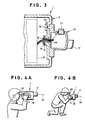
- the zooming button 11 and the video camera start/stop button 16 can be operated with fingers of the hand by which the handgrip is held while viewing and framing a subject on the CRT monitor 21 as is shown in Fig. 4(A) illustrating the portable video camera held at an eye level or high angle camera position. In this way, it is allowed to shift the camera position even from a high angle to a low angle camera position, or from a low angle to a high angle camera position, while continuously shooting scenes.
- the portable video camera 1 can be held at a low angle camera position by glasping the handgrip assembly 10 turned through an appropriate angle.
- the handgrip assembly 10 turned orients the action finder 21 to the eye of the operator in a stooping position. This allows the operator to view the action finder 20 at a relatively high position with holding the portable video camera 1 firmly and to thereby take a easy posture for shooting scenes.
- the action finder 20 is integrally connected to the handgrip assembly 10 turnable according to camera positions, the monitor CRT 21 of the action finder 20 can be brought into alignment with an eye of the operator in any shooting angle, resulting in an easy observation of the monitor CRT 21 of the action finder 20.
- the integral connection of the action finder 20 to the handgrip assembly 10 avoids the provision of a mechanism for moving the action finder 20 according to eye positions or camera angles or positions rather than the mechanism allowing the turning of the handgrip assembly 10.
- the action finder 20, in particular the monitor CRT 21, can be directed downward by extending the groove 4a and accordingly the portable video camera can be used at a high angle camera position.
- a portable video camera 31 according to a another preferred embodiment of the present invention.
- the portable video camera 31 which is basically similar to that of Figure 1, is provided with a zoom lens 33 having the optical axis 33a thereof as a taking lens and a turnable handgrip assembly 40 mounted on one side wall of the camera body 32.
- the zoom lens 33 is automatically focused by an automatic focusing device which is well known in the art and therefor need not be explained in detail herein, and is changeable in focal length by operating a zooming button 34 which is in the form of an externally operable double-throw button and is provided on the top wall of the handgrip assembly 40.
- the handgrip assembly 40 is further provided with an action finder 60 having a view axis 60a integrally connected thereto and an externally operable video camera start/stop button 35.
- the action finder 60 is of an electronic type having a small size CRT monitor 61 which displays an image taken by the zoom lens 33 thereon and an eye piece 62 through which an virtual image of the CRT monitor screen can be viewed at an eye point up to approximately 50 cm.
- Denoted by numerals 67 and 68 in Fig. 5 are an eye cup and a hand strap, respectively.
- the handgrip assembly 40 is, as shown in detail in Fig. 6, rotatably mounted on a mount 37 with an annular rim 37a provided on the side wall of the camera body 32.
- a housing 41 of the handgrip assembly 40 is integrally formed with a mount cap 42 having an opening 43 defined by an annular rim 44.
- the mount 37 is received in the opening 44 of the housing 41 so as to support the handgrip assembly 40 thereon.
- the mount 37 is attached with a supporting disk 45 having a center opening 46 with a set of set screws 47 in such a way as to allow the housing 41 to rotate relative to the camera body 32.
- the supporting disk 45 is provided with a ring 48 such as a rubber ring.
- a half-round of spring band 50 is pivotally mounted on a boss 52 extending from the mount cap 42 so as to surround a half of the periphery of the rubber ring 48.
- the spring band 50 is formed with a plurality of projections 51 on the inner surface thereof and is provided a block 53 fixed to its free end.
- a externally operable knob 54 passing through a generally reversed L-shaped slot 46 comprising arm and stem sections formed in the housing 45.
- the spring band 50 is loosened to allow the handgrip assembly 40 to turn to any possible position relative to the camera body 32.
- the spring band 50 is further provided with a click stop mechanism comprising a resilient lug 50a having a locking member 50b in the form of a hemisphere.
- This lock member 50b is engageable with a locking recess 49 shaped in the form of a hemisphere in the supporting disk 45 so as to lock the handgrip assembly 40 at a position to hold the optical axis 60a of the action finder 60 in parallel with the optical axis 33a of the zoom lens 33.
- a stopper member 38 which is engageable with stepped portions 42a and 42b of the mount cap 42 to limit upward and downward turn of the handgrip assembly 40. It is desirable to dimension the stopper member 38 and the stepped portions 42a and 42b so as to allow the handgrip assembly 40 to turn approximately 80 degrees upwardly and approximately 45 degrees downwardly. It is desirable to form the stopper member 38 as a part of a shassis to which various circuits are attached, the part projecting out of the video camera body 32.
- the zooming button 34 and the video camera start/stop button 35 are connected to a circuitry (not shown) inside the video camera body 32 through wire-bundles 56a and 56b, respectively.
- These wire-bandles 56a and 56b are tied up in a single wire-baundle 56c outside the mount cap 42 and passes through the opening 43 of the mount.
- the single wire-bundle 56c is trained around half the rim 37a of the mount 37 and enters inside the video camera body 32 through an opening 37b formed in the mount 37.
- a top door 35 of the camera body 1 is opened and a video tape cassette is loaded in the portable video camera 31.
- the handgrip assembly 40 is grasped by the right hand of the operator passed through the strap 67 to hold the portable video camera 31.
- the zooming button 31 and the video camera start/stop button 46 can be operated with fingers of the right hand while viewing and framing an image of a subject displayed the CRT monitor 61 through the eye piece 62.
- the locking knob 54 is shifted aside toward right as viewed in Fig. 5 so as to loosen the spring band 50a in order to allow the handgrip assembly 40 to turn.
- the hemispherical ball tip member 50b is received in the recess 49 to stop the handgrip assembly 40 and hold it in parallel with the optical axis 33a of the zoom lens 33.
- the video camera 31 is thereby held at an eye level camera position.
- the locking knob 54 is brought into engagement with the arm section of the L-shaped slot 46 of the housing 41 so as to tighten the spring band 50 against the rubber ring 48 of the supporting disk 45.
- the locking knob 54 When turning the handgrip assembly 40 upward or downward, the locking knob 54 is disengaged from the arm section of the slot 46 and allowed to enter into the stem section of the slot 46 to loosen the spring band 50, allowing the handgrip assembly 40 to be turnable.
- the handgrip assembly 40 can be turn up or down to be tilted at any desired angle.
- the spring band 50 By re-engaging the locking knob 54 with the arm section of the slot 46, the spring band 50 is tightened against the rubber ring 48 of the supporting disk 45 so as to hold the handgrip assembly 40 at a desired turned position, thereby allowing the video camera to be held at a high or low angle camera position.
- the action finder 60 is integrally connected to the handgrip assembly 40 turnable according to camera positions, the monitor CRT 61 of the action finder 60 can be brought into alignment with an eye of the operator in any shooting angle, resulting in an easy observation of the monitor CRT 61 of the action finder 40.
- the integral connection of the action finder 60 to the handgrip assembly 40 avoids the provision of a mechanism for moving the action finder 60 independently from the handgrip assembly 40 according to eye positions or camera angles rather than the mechanism for allowing the turning of the handgrip assembly 10.
- the camera body 71 of the portable camera is provided with a handgrip assembly 74 mounted on a side wall thereof.
- An electronic action finder 77 including a monitor CRT is incorporated in the handgrip assembly 74.
- Electrical elements of the action finder and operating members such as a zooming button, a video recording button and so on are connected to their associated electrical elements inside the camera body 72 by means of flexible wires 83 passing through a bellows 73 connecting the camera body 71 and the handgrip assembly 34.
- the present invention can be applied to video cameras of the type having optical finders.
Abstract
Description
- The present invention relates to a video camera, and more particularly to a portable video camera with a handgrip having a built-in action finder.
- There are well known in the art various portable video cameras having a handgrip attached to the bottom of the camera body and a view finder mounted on the top of the camera body which is adjustable in angular position.
- Recent tendency of portable video cameras is to provide a grip changeable in angle relative the the camera body for easy handling. A problem in association with such a portable video camera is an difficulty of sighting a subject through a view finder of the portable video camera at a low angle camera position. This is due to the view finder built in or mounted on the camera body. There are some large video cameras provided with adjustable view finders. Although the provision of such an adjustable view finder, it is still difficult to handle the large video camera when using it at low angle camera positions because a grip of the large video camera is generally structurally integral with the camera body thereof.
- In some instances, such video cameras of this type it is troublesome to change the camera angle or position between a high angle and low angle camera positions because it is necessary to bend backward the wrist of hand of an operator when shifting the camera in particular from a high angle camera position to a low angle camera position. Additionally, in some of such video cameras of this type two actions are necessary; adjusting the view finder, and thereafter the grip, in angular position. This leads to bring the video camera to a standstill.
- It is, therefore, an object of the present invention to provide a portable video camera which is easily handled at any camera position.
- It is another object of the present invention to provide a portable video camera which is easy to sight a subject through an action finder at any camera position.
- It is still another object of the present invention to provide a portable video camera which is smoothly shiftable between a high angle and a low angle camera position even with a single action and without bring the video camera to a standstill.
- The portable video camera according to the present invention is provided with a view finder which is structurally integral with the handgrip turnable relative to the camera body. The view finder, preferably an action finder, is oriented in cooperation with the handgrip swung to easily hold the video camera according to camera positions, so that the action finder can be brought into alignment with an eye of the operator at any shooting camera position. This leads not only to shifting the video camera with a single action while continuing video photography but also to an easy observation of a subject through the action finder.
- The description refers to th accompanying drawings in which:
- Figure 1 is a perspective view of a portable video camera according to a preferred embodiment of the present invention in which a handgrip is swung up;
- Figure 2 is a perspective exploded view of the portable video camera of Figure 1 in which the handgrip is demounted;
- Figure 3 is a cross sectional view of an essential part of the portable video camera of Figure 1;
- Figure 4(A) is an illustration showing that the portable video camera is used at an eye level camera position;
- Figure 4(B) is an illustration showing that the portable video camera is used at a low angle camera position;
- Figure 5 is a perspective view of a portable video camera according to another preferred embodiment of the present invention;
- Figure 6 is an exploded perspective exploded view of the portable video camera of Figure 5;
- Figure 7 is an explanatory plane view showing of an essential part of a handgrip mounting mechanism of the video camera of Figure 5; and
- Figure 8 is a perspective view of a portable video camera according to still another preferred embodiment of the present invention.
- Referring now to Fig. 1 there is shown a
portable video camera 1 according to a preferred embodiment of the present invention. As shown, theportable video camera 1 is provided with azoom lens 3 having theoptical axis 3a thereof as a taking lens and aturnable handgrip assembly 10 mounted on one side wall of thecamera body 2. Thezoom lens 3 is automatically focused by an automatic focusing device which is well known in the art and therefore no need be explained in detail herein, and is changeable in focal length by means of azooming button 11 in the form of an externally operable double-throw button. In thecamera body 2 an image pick-up unit 25 comprising an image sensing device and an image recording device is disposed, which image sensing device and image recording device are well known to those skilled in the art. The image sensing device, on which an image of a subject is formed by thezoom lens 3, outputs video signals which in turn are recorded in a magnetic recording medium by means of a magnetic recording head in the image recording device after having been properly processed. - In the side wall there is formed a
circular recess 4 with a circulararcuate groove 4a and acenter hole 4b as is best seen in Figs. 2 and 3. Thehandgrip assembly 10 is integrally formed with a connecting shaft 12 with threads at its end which is received in thecenter hole 4b and is held with anut 14 through aspring washer 13. Owing to the provision of thespring washer 13 thehandgrip assembly 10 supported by thecamera body 2 can be turned with a certain friction relative to thecamera body 2 and held at a desired angular position relative to thecamera body 2. Thearcuate groove 4a, which is engaged by apin 15 formed on the inside wall of thehandgrip assembly 10, defines the extremities of swing of thehandgrip assembly 10. It is preferred to provide thecenter hole 4b at the center of gravity of the camera for balancing the video camera on thehandgrip assembly 10 held by a hand. - The
handgrip assembly 10 is further provided with anaction finder 20 having aview axis 20a integrally connected thereto and an externally operablevideo recording button 16. Theaction finder 20 is of the electronic type including a smallsize CRT monitor 21 which displays an image taken by thezoom lens 3 thereon. The image on theCRT monitor 21 is viewed through aneye piece 21a. The externallyoperable buttons CRT monitor 21 are connected to their associated electrical elements in thecamera body 2 by means offlexible wires 23 passing through a bore formed in the connecting shaft 12. Denoted bynumerals - When using the
portable video camera 1, atop door 5 of thecamera body 1 is opened and a video tape cassette is loaded in theportable video camera 1. Thehandgrip assembly 10 is grasped by the right hand of the operator passed through thestrap 17 to hold theportable video camera 1. By thus grasping thehandgrip assembly 1, thezooming button 11 and the video camera start/stop button 16 can be operated with fingers of the hand by which the handgrip is held while viewing and framing a subject on theCRT monitor 21 as is shown in Fig. 4(A) illustrating the portable video camera held at an eye level or high angle camera position. In this way, it is allowed to shift the camera position even from a high angle to a low angle camera position, or from a low angle to a high angle camera position, while continuously shooting scenes. - As illustrated in Fig. 4(B), the
portable video camera 1 can be held at a low angle camera position by glasping thehandgrip assembly 10 turned through an appropriate angle. Thehandgrip assembly 10 turned orients theaction finder 21 to the eye of the operator in a stooping position. This allows the operator to view theaction finder 20 at a relatively high position with holding theportable video camera 1 firmly and to thereby take a easy posture for shooting scenes. - As apparent from the above description, since the
action finder 20 is integrally connected to thehandgrip assembly 10 turnable according to camera positions, themonitor CRT 21 of theaction finder 20 can be brought into alignment with an eye of the operator in any shooting angle, resulting in an easy observation of themonitor CRT 21 of theaction finder 20. The integral connection of the action finder 20 to thehandgrip assembly 10 avoids the provision of a mechanism for moving theaction finder 20 according to eye positions or camera angles or positions rather than the mechanism allowing the turning of thehandgrip assembly 10. - The action finder 20, in particular the monitor CRT 21, can be directed downward by extending the
groove 4a and accordingly the portable video camera can be used at a high angle camera position. - Referring now to Figs. 5 to 7 there is shown a
portable video camera 31 according to a another preferred embodiment of the present invention. As shown, theportable video camera 31, which is basically similar to that of Figure 1, is provided with azoom lens 33 having theoptical axis 33a thereof as a taking lens and aturnable handgrip assembly 40 mounted on one side wall of thecamera body 32. Thezoom lens 33 is automatically focused by an automatic focusing device which is well known in the art and therefor need not be explained in detail herein, and is changeable in focal length by operating azooming button 34 which is in the form of an externally operable double-throw button and is provided on the top wall of thehandgrip assembly 40. Internal mechanisms of thevideo camera 31 are substantially the same as those of the video camera of Figure 1 and need not be explained again. Thehandgrip assembly 40 is further provided with anaction finder 60 having aview axis 60a integrally connected thereto and an externally operable video camera start/stop button 35. Theaction finder 60 is of an electronic type having a smallsize CRT monitor 61 which displays an image taken by thezoom lens 33 thereon and aneye piece 62 through which an virtual image of the CRT monitor screen can be viewed at an eye point up to approximately 50 cm. Denoted bynumerals - The
handgrip assembly 40 is, as shown in detail in Fig. 6, rotatably mounted on amount 37 with anannular rim 37a provided on the side wall of thecamera body 32. Ahousing 41 of thehandgrip assembly 40 is integrally formed with amount cap 42 having anopening 43 defined by anannular rim 44. Themount 37 is received in theopening 44 of thehousing 41 so as to support thehandgrip assembly 40 thereon. In order to prevent thehousing 41 from slipping out from themount 37, themount 37 is attached with a supportingdisk 45 having acenter opening 46 with a set ofset screws 47 in such a way as to allow thehousing 41 to rotate relative to thecamera body 32. The supportingdisk 45 is provided with aring 48 such as a rubber ring. - A half-round of
spring band 50 is pivotally mounted on aboss 52 extending from themount cap 42 so as to surround a half of the periphery of therubber ring 48. Thespring band 50 is formed with a plurality ofprojections 51 on the inner surface thereof and is provided ablock 53 fixed to its free end. Connected to theblock 53 is a externallyoperable knob 54 passing through a generally reversed L-shapedslot 46 comprising arm and stem sections formed in thehousing 45. When a connecting piece of theknob 54 is in the arm section of theslot 46, thespring band 50 is firmly pressed against the outer surface of therubber ring 48 so as to lock thehandgrip assembly 40 at any desired turned position relative to thecamera body 32. However, when the connecting piece of theknob 54 is in the stem section of theslot 46, thespring band 50 is loosened to allow thehandgrip assembly 40 to turn to any possible position relative to thecamera body 32. Thespring band 50 is further provided with a click stop mechanism comprising aresilient lug 50a having a lockingmember 50b in the form of a hemisphere. Thislock member 50b is engageable with a lockingrecess 49 shaped in the form of a hemisphere in the supportingdisk 45 so as to lock thehandgrip assembly 40 at a position to hold theoptical axis 60a of theaction finder 60 in parallel with theoptical axis 33a of thezoom lens 33. - As shown in Fig. 7, on the side wall of the
video camera body 32 there is provided with astopper member 38 which is engageable with steppedportions mount cap 42 to limit upward and downward turn of thehandgrip assembly 40. It is desirable to dimension thestopper member 38 and the steppedportions handgrip assembly 40 to turn approximately 80 degrees upwardly and approximately 45 degrees downwardly. It is desirable to form thestopper member 38 as a part of a shassis to which various circuits are attached, the part projecting out of thevideo camera body 32. - The
zooming button 34 and the video camera start/stop button 35 are connected to a circuitry (not shown) inside thevideo camera body 32 through wire-bundles bandles baundle 56c outside themount cap 42 and passes through theopening 43 of the mount. The single wire-bundle 56c is trained around half therim 37a of themount 37 and enters inside thevideo camera body 32 through anopening 37b formed in themount 37. - When using the
portable video camera 31, atop door 35 of thecamera body 1 is opened and a video tape cassette is loaded in theportable video camera 31. Thehandgrip assembly 40 is grasped by the right hand of the operator passed through thestrap 67 to hold theportable video camera 31. By thus grasping thehandgrip assembly 40, thezooming button 31 and the video camera start/stop button 46 can be operated with fingers of the right hand while viewing and framing an image of a subject displayed the CRT monitor 61 through theeye piece 62. When it is desired to hold the portable video camera and to shoot a subject at an eye level camera position, the lockingknob 54 is shifted aside toward right as viewed in Fig. 5 so as to loosen thespring band 50a in order to allow thehandgrip assembly 40 to turn. By turning thehandgrip assembly 40 in the clockwise direction as viewed in fig. 5, the hemisphericalball tip member 50b is received in therecess 49 to stop thehandgrip assembly 40 and hold it in parallel with theoptical axis 33a of thezoom lens 33. Thevideo camera 31 is thereby held at an eye level camera position. For maintaining thehandgrip assembly 40 at the position, the lockingknob 54 is brought into engagement with the arm section of the L-shapedslot 46 of thehousing 41 so as to tighten thespring band 50 against therubber ring 48 of the supportingdisk 45. - When turning the
handgrip assembly 40 upward or downward, the lockingknob 54 is disengaged from the arm section of theslot 46 and allowed to enter into the stem section of theslot 46 to loosen thespring band 50, allowing thehandgrip assembly 40 to be turnable. Thehandgrip assembly 40 can be turn up or down to be tilted at any desired angle. By re-engaging the lockingknob 54 with the arm section of theslot 46, thespring band 50 is tightened against therubber ring 48 of the supportingdisk 45 so as to hold thehandgrip assembly 40 at a desired turned position, thereby allowing the video camera to be held at a high or low angle camera position. - As apparent from the above description, since the
action finder 60 is integrally connected to thehandgrip assembly 40 turnable according to camera positions, themonitor CRT 61 of theaction finder 60 can be brought into alignment with an eye of the operator in any shooting angle, resulting in an easy observation of themonitor CRT 61 of theaction finder 40. The integral connection of theaction finder 60 to thehandgrip assembly 40 avoids the provision of a mechanism for moving theaction finder 60 independently from thehandgrip assembly 40 according to eye positions or camera angles rather than the mechanism for allowing the turning of thehandgrip assembly 10. - Referring now to Fig. 8 showing a portable video camera according to another preferred embodiment of the present invention, the
camera body 71 of the portable camera is provided with ahandgrip assembly 74 mounted on a side wall thereof. Anelectronic action finder 77 including a monitor CRT is incorporated in thehandgrip assembly 74. Electrical elements of the action finder and operating members such as a zooming button, a video recording button and so on are connected to their associated electrical elements inside the camera body 72 by means of flexible wires 83 passing through abellows 73 connecting thecamera body 71 and thehandgrip assembly 34. - It is to be noted that the present invention can be applied to video cameras of the type having optical finders.
- The present invention has been shown and described with reference to specific embodiments. However, it should be noted that the invention is in no way limited to the details of the illustrated embodiments, and changes and modifications may be made without departing from the scope of the apended claims.
Claims (23)
a camera body having a lens and a device for producing a video image;
a handgrip to be grasped by a hand to hold said video camera body which is turnably mounted on one side wall of said camera body; and
a view finder structurally integral with said handgrip for viewing an object.
a camera body having a lens and a device for producing a video image;
a handgrip to be grasped by a hand to hold said camera body which is turnably mounted on one side wall of said camera body;
a camera position changing mechanism operationally interconnecting said camera body and said handgrip for allowing said handgrip to be turned relative to said camera body through a desired angle, thereby changing a camera position of said video camera between a high and a low angle camera position; and
an electronic view finder structurally integral with said handgrip for viewing an image of an object.
a camera body having a lens and a device for producing a video image;
a mount formed on one side wall of said camera body;
a handgrip to be grasped by a hand to hold said camera body, said handgrip being mounted on said mount for up and down turn;
a camera position changing mechanism operationally interconnecting said camera body and said handgrip for allowing said handgrip to be turned to said camera body through a desired angle, thereby changing a camera position of said video camera between a high and a low camera position,
an electronic view finder structurally integral with said handgrip for viewing an image of an object; and
an externally operable video camera control button provided on a housing of said handgrip, said video camera control button being connected to circuitry in said camera body by means of a wire bundle.
Applications Claiming Priority (2)
| Application Number | Priority Date | Filing Date | Title |
|---|---|---|---|
| JP17946187 | 1987-11-25 | ||
| JP179461/87U | 1987-11-25 |
Publications (3)
| Publication Number | Publication Date |
|---|---|
| EP0318015A2 true EP0318015A2 (en) | 1989-05-31 |
| EP0318015A3 EP0318015A3 (en) | 1990-08-22 |
| EP0318015B1 EP0318015B1 (en) | 1995-02-01 |
Family
ID=16066256
Family Applications (1)
| Application Number | Title | Priority Date | Filing Date |
|---|---|---|---|
| EP88119618A Expired - Lifetime EP0318015B1 (en) | 1987-11-25 | 1988-11-24 | Video camera |
Country Status (3)
| Country | Link |
|---|---|
| US (1) | US4959729A (en) |
| EP (1) | EP0318015B1 (en) |
| DE (1) | DE3852926T2 (en) |
Cited By (3)
| Publication number | Priority date | Publication date | Assignee | Title |
|---|---|---|---|---|
| EP0400944A2 (en) * | 1989-05-30 | 1990-12-05 | Sony Corporation | Unified compact video camera and VCR |
| GB2236032B (en) * | 1989-06-27 | 1994-04-06 | Minolta Camera Kk | Infrared image pick-up apparatus |
| EP1901548A3 (en) * | 2006-09-12 | 2011-05-04 | Samsung Electronics Co., Ltd. | Photography apparatus |
Families Citing this family (27)
| Publication number | Priority date | Publication date | Assignee | Title |
|---|---|---|---|---|
| JPH02260771A (en) * | 1989-03-30 | 1990-10-23 | Canon Inc | Video recorder device united with camera |
| US5034822A (en) * | 1989-09-13 | 1991-07-23 | Stevens William M | Video camera adaptor for film cameras |
| US5548334A (en) * | 1990-01-11 | 1996-08-20 | Canon Kabushiki Kaisha | Video camera having viewfinder rotatably mounted on camera body |
| JPH03273769A (en) * | 1990-01-16 | 1991-12-04 | Hitachi Ltd | Camera integrated with vtr |
| US5657083A (en) * | 1991-09-05 | 1997-08-12 | Canon Kabushiki Kaisha | Video camera having parts arranged to reduce affects of shake |
| JPH04144368A (en) * | 1990-10-04 | 1992-05-18 | Fuji Photo Film Co Ltd | Camera |
| JPH04287574A (en) * | 1991-03-18 | 1992-10-13 | Fuji Photo Film Co Ltd | Video camera provided with liquid crystal finder |
| US5343263A (en) * | 1991-05-10 | 1994-08-30 | Fuji Photo Optical Co., Ltd. | Lens grip coupling and positioning mechanism |
| CA2101040C (en) * | 1992-07-30 | 1998-08-04 | Minori Takagi | Video tape recorder with a monitor-equipped built-in camera |
| JP3183056B2 (en) * | 1994-08-26 | 2001-07-03 | 株式会社日立製作所 | Imaging device |
| KR0113218Y1 (en) * | 1994-11-25 | 1998-04-13 | 이헌조 | Handgrip unified l.c.d. for camcordr |
| US5946512A (en) * | 1998-03-11 | 1999-08-31 | Eastman Kodak Company | Compact camera with variable position handgrip |
| JP4387546B2 (en) * | 2000-03-22 | 2009-12-16 | 株式会社リコー | CAMERA, IMAGE INPUT DEVICE, MOBILE TERMINAL DEVICE, AND CAMERA FORM CHANGE METHOD |
| US6927797B2 (en) * | 2001-04-19 | 2005-08-09 | Panavision Inc. | Viewfinder for high definition video camera |
| JP2004147233A (en) * | 2002-10-25 | 2004-05-20 | Sony Corp | Video camera |
| JP4426804B2 (en) * | 2003-09-19 | 2010-03-03 | 株式会社日立製作所 | Video camera |
| CN100342256C (en) * | 2003-12-23 | 2007-10-10 | 明基电通股份有限公司 | Rotating mechanism |
| JP4391882B2 (en) * | 2004-05-12 | 2009-12-24 | Hoya株式会社 | Rotating shaft structure and camera grip rotating shaft structure |
| TWI239425B (en) * | 2004-07-21 | 2005-09-11 | Benq Corp | Image capturing device |
| JP4148198B2 (en) * | 2004-07-30 | 2008-09-10 | フジノン株式会社 | Auto focus system |
| EP1762889A1 (en) * | 2005-09-07 | 2007-03-14 | Thomson Licensing | Camera body of a video system with a handgrip and video system therewith |
| US7878718B2 (en) * | 2006-09-12 | 2011-02-01 | Samsung Electronics Co., Ltd. | Image photographing apparatus and rotatable gripping unit of same |
| KR101475412B1 (en) * | 2007-06-27 | 2014-12-22 | 삼성전자주식회사 | Grip device and image photography apparatus having the same |
| DE102008059175A1 (en) * | 2008-11-25 | 2010-05-27 | Stefan Guder | Electronic vision aid for assisting visually-impaired persons suffering from age-related macular degeneration, has batteries charged by charging device, and handy device provided for user and either held in hand or hanged by shoulder strap |
| US8628257B2 (en) * | 2011-10-26 | 2014-01-14 | Canon Kabushiki Kaisha | Image-pickup apparatus, camera grip, and image-pickup system |
| JP6289190B2 (en) * | 2014-03-19 | 2018-03-07 | キヤノン株式会社 | Imaging device |
| US10732491B2 (en) * | 2017-03-24 | 2020-08-04 | Canon Kabushiki Kaisha | Image pickup apparatus to which accessory is removably attached, and image pickup system |
Citations (3)
| Publication number | Priority date | Publication date | Assignee | Title |
|---|---|---|---|---|
| JPS59158175A (en) * | 1983-02-28 | 1984-09-07 | Nippon Kogaku Kk <Nikon> | Video camera |
| US4494147A (en) * | 1981-04-16 | 1985-01-15 | Canon Kabushiki Kaisha | Video camera |
| JPS61177870A (en) * | 1985-02-01 | 1986-08-09 | Matsushita Electric Ind Co Ltd | Photographing device |
Family Cites Families (6)
| Publication number | Priority date | Publication date | Assignee | Title |
|---|---|---|---|---|
| JPS56147436U (en) * | 1980-04-05 | 1981-11-06 | ||
| JPS5995336U (en) * | 1982-12-17 | 1984-06-28 | ソニー株式会社 | Video camera |
| JPS6019269U (en) * | 1983-07-15 | 1985-02-09 | オリンパス光学工業株式会社 | Video camera |
| US4591254A (en) * | 1984-10-26 | 1986-05-27 | Bronislaw Sokolowski | Adaptor for T.V. camera |
| KR910001707Y1 (en) * | 1986-06-05 | 1991-03-18 | 니뽕 빅터 가부시끼가이샤 | Camcorder |
| US4705374A (en) * | 1986-09-11 | 1987-11-10 | Clairmont Camera, Inc. | Tilting viewfinder and video door accessory for motion-picture camera |
-
1988
- 1988-11-24 DE DE3852926T patent/DE3852926T2/en not_active Expired - Lifetime
- 1988-11-24 EP EP88119618A patent/EP0318015B1/en not_active Expired - Lifetime
- 1988-11-25 US US07/275,889 patent/US4959729A/en not_active Expired - Lifetime
Patent Citations (3)
| Publication number | Priority date | Publication date | Assignee | Title |
|---|---|---|---|---|
| US4494147A (en) * | 1981-04-16 | 1985-01-15 | Canon Kabushiki Kaisha | Video camera |
| JPS59158175A (en) * | 1983-02-28 | 1984-09-07 | Nippon Kogaku Kk <Nikon> | Video camera |
| JPS61177870A (en) * | 1985-02-01 | 1986-08-09 | Matsushita Electric Ind Co Ltd | Photographing device |
Non-Patent Citations (2)
| Title |
|---|
| PATENT ABSTRACTS OF JAPAN, vol. 10, no. 386 (E-467), 24th December 1986; & JP-A-61 177 870 (MATSUSHITA ELECTRIC IND. CO. LTD) 09-08-1986 * |
| PATENT ABSTRACTS OF JAPAN, vol. 9, no. 8 (E-289)[1731], 12th January 1985; & JP-A-59 158 175 (NIHON KOUGAKU KOGYO K.K.) 07-09-1984 * |
Cited By (7)
| Publication number | Priority date | Publication date | Assignee | Title |
|---|---|---|---|---|
| EP0400944A2 (en) * | 1989-05-30 | 1990-12-05 | Sony Corporation | Unified compact video camera and VCR |
| EP0400944A3 (en) * | 1989-05-30 | 1992-08-26 | Sony Corporation | Unified compact video camera and vcr |
| TR25434A (en) * | 1989-05-30 | 1993-03-01 | Sony Corp | UNITED COMPACT VIDEO CAMERA AND VCR. |
| EP0702486A2 (en) * | 1989-05-30 | 1996-03-20 | Sony Corporation | Unified compact video camera and VCR |
| EP0702486A3 (en) * | 1989-05-30 | 1997-10-01 | Sony Corp | Unified compact video camera and VCR |
| GB2236032B (en) * | 1989-06-27 | 1994-04-06 | Minolta Camera Kk | Infrared image pick-up apparatus |
| EP1901548A3 (en) * | 2006-09-12 | 2011-05-04 | Samsung Electronics Co., Ltd. | Photography apparatus |
Also Published As
| Publication number | Publication date |
|---|---|
| EP0318015A3 (en) | 1990-08-22 |
| US4959729A (en) | 1990-09-25 |
| EP0318015B1 (en) | 1995-02-01 |
| DE3852926T2 (en) | 1995-05-24 |
| DE3852926D1 (en) | 1995-03-16 |
Similar Documents
| Publication | Publication Date | Title |
|---|---|---|
| US4959729A (en) | Video camera having rotatable viewfinder | |
| EP0622663B1 (en) | Camera grip with gear mechanism | |
| US6226448B1 (en) | Video tape recorder with a monitor-equipped built-in camera | |
| US8328359B2 (en) | Camera stabilizer | |
| US4439030A (en) | Connecting device for an endoscopic television camera | |
| JPH089204A (en) | Video camera | |
| JP4380475B2 (en) | Imaging device | |
| US4736217A (en) | Camera platform for tripod mounting | |
| JPH0742894A (en) | Extension grip with built-in tripod | |
| US4409619A (en) | Television camera with an electronic view finder | |
| US6686967B1 (en) | Low-angle grip device for an ENG camera | |
| CN110290294A (en) | It will be used for picture pick-up device of the connector arrangement in optimum position of external device (ED) | |
| JPH0512901B2 (en) | ||
| JPWO2007077759A1 (en) | Imaging device | |
| JPH0360101B2 (en) | ||
| WO1997008888A1 (en) | Recorder equipped with video camera | |
| JPH0628860Y2 (en) | Video camera | |
| JPH11289482A (en) | Electronic camera | |
| US11886100B2 (en) | Support apparatus for electronic device, and electronic device | |
| JP2006074695A (en) | Imaging apparatus and shoe adapter | |
| JPH062368Y2 (en) | Video camera | |
| JP4133542B2 (en) | Video camera | |
| JPH02311089A (en) | Video camera | |
| JPS63311876A (en) | Video camera supporter | |
| JPH0418297Y2 (en) |
Legal Events
| Date | Code | Title | Description |
|---|---|---|---|
| PUAI | Public reference made under article 153(3) epc to a published international application that has entered the european phase |
Free format text: ORIGINAL CODE: 0009012 |
|
| AK | Designated contracting states |
Kind code of ref document: A2 Designated state(s): DE FR GB |
|
| PUAL | Search report despatched |
Free format text: ORIGINAL CODE: 0009013 |
|
| AK | Designated contracting states |
Kind code of ref document: A3 Designated state(s): DE FR GB |
|
| 17P | Request for examination filed |
Effective date: 19901113 |
|
| 17Q | First examination report despatched |
Effective date: 19920810 |
|
| GRAA | (expected) grant |
Free format text: ORIGINAL CODE: 0009210 |
|
| AK | Designated contracting states |
Kind code of ref document: B1 Designated state(s): DE FR GB |
|
| REF | Corresponds to: |
Ref document number: 3852926 Country of ref document: DE Date of ref document: 19950316 |
|
| ET | Fr: translation filed | ||
| PLBE | No opposition filed within time limit |
Free format text: ORIGINAL CODE: 0009261 |
|
| STAA | Information on the status of an ep patent application or granted ep patent |
Free format text: STATUS: NO OPPOSITION FILED WITHIN TIME LIMIT |
|
| 26N | No opposition filed | ||
| REG | Reference to a national code |
Ref country code: GB Ref legal event code: IF02 |
|
| REG | Reference to a national code |
Ref country code: GB Ref legal event code: 732E |
|
| REG | Reference to a national code |
Ref country code: FR Ref legal event code: TP Ref country code: FR Ref legal event code: CD |
|
| PGFP | Annual fee paid to national office [announced via postgrant information from national office to epo] |
Ref country code: FR Payment date: 20071116 Year of fee payment: 20 Ref country code: GB Payment date: 20071122 Year of fee payment: 20 |
|
| PGFP | Annual fee paid to national office [announced via postgrant information from national office to epo] |
Ref country code: DE Payment date: 20071228 Year of fee payment: 20 |
|
| REG | Reference to a national code |
Ref country code: GB Ref legal event code: PE20 Expiry date: 20081123 |
|
| PG25 | Lapsed in a contracting state [announced via postgrant information from national office to epo] |
Ref country code: GB Free format text: LAPSE BECAUSE OF EXPIRATION OF PROTECTION Effective date: 20081123 |