EP0317771B1 - Effective diffuser/thickener screen backflushing - Google Patents
Effective diffuser/thickener screen backflushing Download PDFInfo
- Publication number
- EP0317771B1 EP0317771B1 EP88117659A EP88117659A EP0317771B1 EP 0317771 B1 EP0317771 B1 EP 0317771B1 EP 88117659 A EP88117659 A EP 88117659A EP 88117659 A EP88117659 A EP 88117659A EP 0317771 B1 EP0317771 B1 EP 0317771B1
- Authority
- EP
- European Patent Office
- Prior art keywords
- pulp
- vessel
- screens
- liquid
- cylinder
- Prior art date
- Legal status (The legal status is an assumption and is not a legal conclusion. Google has not performed a legal analysis and makes no representation as to the accuracy of the status listed.)
- Expired - Lifetime
Links
- 239000002562 thickening agent Substances 0.000 title description 2
- 239000007788 liquid Substances 0.000 claims abstract description 59
- 230000000694 effects Effects 0.000 claims abstract description 9
- 238000004891 communication Methods 0.000 claims abstract description 6
- 239000012530 fluid Substances 0.000 claims abstract description 5
- 238000000605 extraction Methods 0.000 claims description 17
- 238000000034 method Methods 0.000 claims description 16
- 239000007921 spray Substances 0.000 claims description 4
- 238000012216 screening Methods 0.000 claims description 2
- 229920001131 Pulp (paper) Polymers 0.000 abstract description 3
- 230000032258 transport Effects 0.000 abstract 1
- 238000009792 diffusion process Methods 0.000 description 10
- 238000005406 washing Methods 0.000 description 7
- 238000004061 bleaching Methods 0.000 description 6
- 239000000463 material Substances 0.000 description 6
- 238000006073 displacement reaction Methods 0.000 description 5
- 230000008719 thickening Effects 0.000 description 4
- 238000009434 installation Methods 0.000 description 3
- RTAQQCXQSZGOHL-UHFFFAOYSA-N Titanium Chemical compound [Ti] RTAQQCXQSZGOHL-UHFFFAOYSA-N 0.000 description 2
- 238000004140 cleaning Methods 0.000 description 2
- 229910052719 titanium Inorganic materials 0.000 description 2
- 239000010936 titanium Substances 0.000 description 2
- 239000007844 bleaching agent Substances 0.000 description 1
- 230000007423 decrease Effects 0.000 description 1
- 230000001934 delay Effects 0.000 description 1
- 239000000835 fiber Substances 0.000 description 1
- 230000000977 initiatory effect Effects 0.000 description 1
- 238000007689 inspection Methods 0.000 description 1
- 238000005086 pumping Methods 0.000 description 1
- 238000005096 rolling process Methods 0.000 description 1
- 239000000725 suspension Substances 0.000 description 1
Images

Classifications
-
- D—TEXTILES; PAPER
- D21—PAPER-MAKING; PRODUCTION OF CELLULOSE
- D21F—PAPER-MAKING MACHINES; METHODS OF PRODUCING PAPER THEREON
- D21F1/00—Wet end of machines for making continuous webs of paper
- D21F1/66—Pulp catching, de-watering, or recovering; Re-use of pulp-water
-
- B—PERFORMING OPERATIONS; TRANSPORTING
- B01—PHYSICAL OR CHEMICAL PROCESSES OR APPARATUS IN GENERAL
- B01D—SEPARATION
- B01D33/00—Filters with filtering elements which move during the filtering operation
- B01D33/01—Filters with filtering elements which move during the filtering operation with translationally moving filtering elements, e.g. pistons
- B01D33/03—Filters with filtering elements which move during the filtering operation with translationally moving filtering elements, e.g. pistons with vibrating filter elements
- B01D33/0307—Filters with filtering elements which move during the filtering operation with translationally moving filtering elements, e.g. pistons with vibrating filter elements with bag, cage, hose, tube, sleeve or the like filtering elements
- B01D33/0315—Filters with filtering elements which move during the filtering operation with translationally moving filtering elements, e.g. pistons with vibrating filter elements with bag, cage, hose, tube, sleeve or the like filtering elements arranged for inward flow filtration
-
- D—TEXTILES; PAPER
- D21—PAPER-MAKING; PRODUCTION OF CELLULOSE
- D21C—PRODUCTION OF CELLULOSE BY REMOVING NON-CELLULOSE SUBSTANCES FROM CELLULOSE-CONTAINING MATERIALS; REGENERATION OF PULPING LIQUORS; APPARATUS THEREFOR
- D21C9/00—After-treatment of cellulose pulp, e.g. of wood pulp, or cotton linters ; Treatment of dilute or dewatered pulp or process improvement taking place after obtaining the raw cellulosic material and not provided for elsewhere
- D21C9/02—Washing ; Displacing cooking or pulp-treating liquors contained in the pulp by fluids, e.g. wash water or other pulp-treating agents
- D21C9/04—Washing ; Displacing cooking or pulp-treating liquors contained in the pulp by fluids, e.g. wash water or other pulp-treating agents in diffusers ; Washing of pulp of fluid consistency without substantially thickening
-
- B—PERFORMING OPERATIONS; TRANSPORTING
- B01—PHYSICAL OR CHEMICAL PROCESSES OR APPARATUS IN GENERAL
- B01D—SEPARATION
- B01D33/00—Filters with filtering elements which move during the filtering operation
- B01D33/01—Filters with filtering elements which move during the filtering operation with translationally moving filtering elements, e.g. pistons
- B01D33/03—Filters with filtering elements which move during the filtering operation with translationally moving filtering elements, e.g. pistons with vibrating filter elements
- B01D33/0307—Filters with filtering elements which move during the filtering operation with translationally moving filtering elements, e.g. pistons with vibrating filter elements with bag, cage, hose, tube, sleeve or the like filtering elements
- B01D33/033—Filters with filtering elements which move during the filtering operation with translationally moving filtering elements, e.g. pistons with vibrating filter elements with bag, cage, hose, tube, sleeve or the like filtering elements arranged for outward flow filtration
-
- B—PERFORMING OPERATIONS; TRANSPORTING
- B01—PHYSICAL OR CHEMICAL PROCESSES OR APPARATUS IN GENERAL
- B01D—SEPARATION
- B01D33/00—Filters with filtering elements which move during the filtering operation
- B01D33/35—Filters with filtering elements which move during the filtering operation with multiple filtering elements characterised by their mutual disposition
- B01D33/37—Filters with filtering elements which move during the filtering operation with multiple filtering elements characterised by their mutual disposition in parallel connection
- B01D33/39—Filters with filtering elements which move during the filtering operation with multiple filtering elements characterised by their mutual disposition in parallel connection concentrically or coaxially
-
- B—PERFORMING OPERATIONS; TRANSPORTING
- B01—PHYSICAL OR CHEMICAL PROCESSES OR APPARATUS IN GENERAL
- B01D—SEPARATION
- B01D33/00—Filters with filtering elements which move during the filtering operation
- B01D33/44—Regenerating the filter material in the filter
- B01D33/48—Regenerating the filter material in the filter by flushing, e.g. counter-current air-bumps
-
- B—PERFORMING OPERATIONS; TRANSPORTING
- B01—PHYSICAL OR CHEMICAL PROCESSES OR APPARATUS IN GENERAL
- B01D—SEPARATION
- B01D33/00—Filters with filtering elements which move during the filtering operation
- B01D33/58—Handling the filter cake in the filter for purposes other than for regenerating the filter cake remaining on the filtering element
- B01D33/60—Handling the filter cake in the filter for purposes other than for regenerating the filter cake remaining on the filtering element for washing
-
- B—PERFORMING OPERATIONS; TRANSPORTING
- B01—PHYSICAL OR CHEMICAL PROCESSES OR APPARATUS IN GENERAL
- B01D—SEPARATION
- B01D33/00—Filters with filtering elements which move during the filtering operation
- B01D33/70—Filters with filtering elements which move during the filtering operation having feed or discharge devices
- B01D33/76—Filters with filtering elements which move during the filtering operation having feed or discharge devices for discharging the filter cake, e.g. chutes
- B01D33/763—Filters with filtering elements which move during the filtering operation having feed or discharge devices for discharging the filter cake, e.g. chutes for continuously discharging concentrated liquid
Definitions
- the backflushing liquid is supplied from within the vessel itself, rather than from the exterior of the vessel.
- the backflushing liquid is provided, according to the invention, from a cylinder which is mounted to the bottom of the screen supporting conduit.
- the cylinder has a first open end in communication with the interior of the screen support conduit, and a second open end in open communication with the pulp being treated within the vessel.
- a piston is mounted within the cylinder, and relative movement between the piston and cylinder is effected.
- Utilizing the invention not only is it possible to eliminate the accumulator, piping, and its other associated components as described above, but it is also possible to more efficiently treat a larger capacity of pulp. For example, according to the invention it is possible to increase capacity of pulp being treated by as much as about 15% in the case of diffusion washing, while increasing the efficiency of the diffusion washing by as much as 20 to 30%. Since the entire volume of backflushing liquid is provided from within the vessel itself, surge is eliminated thereby expanding the number of treatment techniques that can be practiced utilizing the invention.
- a method of effecting treatment of pulp with screens while minimizing screen clogging is provided, utilizing a generally upright vessel having a pulp inlet and a pulp outlet, the screens mounted to a supporting conduit within the vessel, and the screens having screening surfaces extending generally vertically.
- the method comprises the steps of: (a) Passing pulp generally vertically in the vessel from the inlet to the outlet. (b) Effecting substantially continuous extraction of liquid from the screens through the screen support conduit at a predetermined flow rate. (c) Effecting generally vertical movement of the screens and support conduit in the direction of pulp flow at a first speed, and in the direction opposite pulp flow at a second speed much higher than the first speed.
- a significant object according to the present invention is to effectively back flush screens in a pulp treatment vessel in a simple manner.
- FIGURE 1 illustrates a conventional diffusion washer which is used for washing paper pulp, and effects backflushing of the screens to keep them unclogged.
- This conventional apparatus indicated generally by reference numeral 10, includes a generally upright vessel 11 having a pulp inlet 12 and a pulp outlet 13 which are vertically spaced from each other. The pulp is introduced into the pulp inlet 12, which typically is at the bottom, and flows vertically within the vessel 11, being discharged through the conduit 13 adjacent the top.
- the basic operative components of the device 10 comprise a plurality of concentric cylindrical screens 14, having screen faces 15 which are generally vertical and are in contact with the pulp.
- the concentric screens 14 are supported on support conduits 16, which typically are in the shape of arms extending radially outwardly from a central hub section 17.
- the conduits 16 are hollow, and the interior may be divided into chambers if desirable.
- the screen arms 16 are mounted for reciprocation in the vertical directions by a reciprocating power structure or structures, preferably three or more hydraulic cylinders 18 which are equally spaced around the periphery of the device 10.
- the cylinders 18 reciprocate the screens 14 and support arms 16 so that they move very slowly in the direction of pulp movement (arrows A in FIGURE 1) until the end of the vertical stroke is reached, and then reverse and move opposite to the direction A. While the relative speeds in direction A and opposite to direction A can be varied, in many installations the movement in direction A is much slower than the movement in the direction opposite to A (i.e. downwardly in the exemplary embodiment illustrated). This serves to assist in keeping the screens 14 relatively clog-free.
- a significant difficulty is that when back flush liquid is being supplied to the vessel 11 from the accumulator 24, a "surge" takes place in the vessel 11 since the interior volume of fluent material increases.
- Another difficulty is associated with the constant switching on and switching off of the on/off valves 21, 23, with resultant time delays, the pulp treatment is not as efficient as desirable, and which capacity is limited.
- most accumulators typically discharge the liquid initially at a high pressure, and then at a lesser pressure as the gas driving the liquid out of the accumulator increases its volume.
- the on/off valves 21, 23, pump 25, and accumulator 24 (which must be made of expensive material such as titanium for some uses, such as displacement bleaching) are very expensive.
- FIGURES 2 through 5 One exemplary embodiment of the invention is illustrated in FIGURES 2 through 5, with portions of a second embodiment illustrated in FIGURE 6. According to the invention all of the above-mentioned problems associated with the prior art have been eliminated in a simple and effective manner. Utilizing the structures such as illustrated in FIGURES 2 through 5 for diffusion washing, for example, it is possible to increase capacity by as much as about 15%, and to increase washing efficiency by as much as about 20 to 30%, compared to the conventional diffusion washers illustrated in FIGURE 1.
- FIGURES 2 through 5 Component parts of the structure illustrated in FIGURES 2 through 5 that are comparable to those in FIGURE 1 are illustrated by the same reference numeral only preceded by a "1".
- the device 110 is very similar to the device 10, the major difference being the apparatus and manner for backflushing. Rather than periodically terminating extraction through conduit 120, in the device 110 extraction is essentially continuous.
- the control valve (as opposed to an off/off valve) 40 is controlled to regulate the rate at which liquid is being extracted from the pulp, which will depend upon whether or not the pulp is being thickened or diluted or retaining the same consistency, the treatment liquid, etc.
- the source of backflushing liquid is located interiorly of the vessel 111 rather than exteriorly thereof. What this means is that when backflushing occurs there is no surge within the vessel 111 since the volume of fluent material within the vessel 111 remains essentially the same.
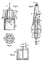
- the backflushing apparatus in the preferred embodiment illustrated in FIGURES 2 through 5, comprises a simple cylinder 42 which is open at both ends thereof.
- the first end 43 is open into the interior of the conduit 116, and the second end 44 is open to the volume of pulp within the vessel 111.
- Mounted within the cylinder 42 for relative reciprocation with respect to the cylinder 42 is a piston 46, which is connected to a piston rod 47.
- that piston rod 47 which may be composed of several sections as illustrated by the connector 48 (see FIGURES 2 and 5), is ultimately connected to a small hydraulic cylinder 49 mounted atop the entire device 110.
- the cylinder 49 effects movement of the piston 46 with respect to the cylinder 42.
- the cylinder 42 and piston 46 need not be made of any special materials, and no particular care is necessary to see that there is a tight seal therebetween. Small amounts of leakage between the piston 46 and cylinder 42 are inconsequential. It is only important to make sure that the piston 46 and cylinder 42 are of compatible material so that they do not harm each other.
- FIGURES 3 and 4 illustrate in somewhat more detail than FIGURE 2 one way in which the cylinder 42 can be attached to the hub section of the conduits 116. These exact details of attachment are not particularly significant as far as the invention is concerned, however, it being necessary only to make sure that the connection is secure and that there is a free flow of extraction/backflushing liquid through the hole 50 in the bottom of the hub section of conduits 116, and the open first end 43 of the cylinder 42.
- FIGURE 5 illustrates the details of the top portion of the device 110 and shows how the piston rod 47 passes through stuffing box 52, and through the conventional pipes 53, 54 which supply the treatment fluid to the arms 130.
- FIGURE 6 illustrates an embodiment in which the piston remains stationary.
- structures generally comparable to those in the FIGURES 2 through 5 embodiment are illustrated by the same reference numeral only preceded by a "2".
- the piston 246 is mounted stationary with respect to the vessel 111 since the rod 247 is connected to a support structure 60 at the top of the device 110 in a relatively rigid manner.
- cooperating nuts 61, 62 are shown which engage a threaded end of the piston rod 247 and therefore hold it in place.
- the relative movement between the piston 246 and the cylinder 242 takes place solely as a result of action by the cylinders 118, and the "zero" position of the components is as illustrated in FIGURE 6, with the piston 246 adjacent the bottom, or second open end 244, of the cylinder 242.
- the pulp flows into inlet 112 and upwardly in direction A in vessel 111, ultimately being discharged through discharge 113.
- Treatment liquid such as wash liquid or bleach liquid, is continuously added to the pulp via the rotating arms 130 and the vertical spray tubes 131 depending therefrom. Liquid is withdrawn from the pulp through the screens 114, into the support conduits 116, passing out the conduit 120 through the control valve 40.
- the cylinders 118 move the support conduits 116 and the screens 114 slowly upwardly in the direction of pulp movement until the end of the stroke is reached, and then move them quickly downwardly at the end of the upward stroke, to the bottommost position.
- the cylinder 49 is actuated to quickly move the piston 46 upwardly with respect to the cylinder 42.
- the exact speed of movement is not particularly critical, typically the system would be designed so that it took about two seconds for the piston 46 to move from its lowermost position (in which the volume within the cylinder 42 was filled with a maximum amount of backflushing/extraction liquid from the conduits 116 and with a minimum amount of pulp), to a more upward position (in which the cylinder 42 was filled with a minimum amount of back flush/extraction liquid and a maximum amount of pulp).
- the system is preferably designed so that the effective volume of the cylinder 42 (that is the amount of back flush/extraction liquid that it will contain at the start of the backflushing operation) is enough to effect efficient backflushing. Extraction continues during backflushing.
- the effective volume of the cylinder 42 will be between about 10,000-12,000 liters, or roughly twice the amount of liquid extracted in a minute.
- the cylinder 49 slowly moves the piston 46 downwardly. As it does this, liquid from conduits 116 passes into the cylinder 42 above the piston rod 46. This generally displaces the pulp from behind the piston 46, as the piston 46 moves slowly downwardly in the cylinder 42, and the cylinder 42 fills with liquid from conduits 116.
- FIGURE 6 embodiment is also effective in backflushing the screens, it may be considered to be slightly less effective than the embodiment of FIGURES 2 through 5 since the backflushing action will not start until there has been downward movement of the entire conduit/screen assembly 116, 114.
- the length of the cylinder 42, 242 be designed considering the stroke of the cylinders 118, and whether or not there will be an additional, separate stroke of the piston rod (the FIGURES 2 through 5 embodiment).
- the "backflushing" components used in the method can be considered to be a liquid pumping means in general, located within the vessel and including a chamber defining element (cylinder) and liquid engaging element (piston). While a piston and cylinder are the simplest and therefore the preferred form of such components, other equivalent fluid components, such as a rolling diaphragm in a cylinder, etc., can be utilized where specific requirements call for it.
Landscapes
- Life Sciences & Earth Sciences (AREA)
- Engineering & Computer Science (AREA)
- Wood Science & Technology (AREA)
- Chemical & Material Sciences (AREA)
- Chemical Kinetics & Catalysis (AREA)
- Paper (AREA)
- Pharmaceuticals Containing Other Organic And Inorganic Compounds (AREA)
- Superconductors And Manufacturing Methods Therefor (AREA)
- Battery Electrode And Active Subsutance (AREA)
- Extrusion Moulding Of Plastics Or The Like (AREA)
- Manipulator (AREA)
- Photoreceptors In Electrophotography (AREA)
- Filtration Of Liquid (AREA)
- Disintegrating Or Milling (AREA)
- Nitrogen And Oxygen Or Sulfur-Condensed Heterocyclic Ring Systems (AREA)
- Polysaccharides And Polysaccharide Derivatives (AREA)
- Bidet-Like Cleaning Device And Other Flush Toilet Accessories (AREA)
- Glass Compositions (AREA)
- Preparation Of Clay, And Manufacture Of Mixtures Containing Clay Or Cement (AREA)
- Networks Using Active Elements (AREA)
- Separation Of Suspended Particles By Flocculating Agents (AREA)
- Nitrogen Condensed Heterocyclic Rings (AREA)
- Prostheses (AREA)
- Diaphragms For Electromechanical Transducers (AREA)
- Centrifugal Separators (AREA)
- Cyclones (AREA)
- Aeration Devices For Treatment Of Activated Polluted Sludge (AREA)
- External Artificial Organs (AREA)
Abstract
Description
- There are a number of paper pulp treating operations in which screens mounted on a reciprocal supporting conduit are disposed in a vessel. Thickening, displacement bleaching, and diffusion washing are three typical types of operations which are accomplished utilizing apparatus as typified by US-A-3,704,603, US-A-3,760,948, and US-A-4,172,037. While such techniques are imminently effective for treating pulp, they are not without their drawbacks.
- One drawback that limits the versatility of such techniques is the fact that in many installations, in order to prevent the screens from clogging a volume of backflushing liquid is periodically introduced into the vessels. This causes a surge in the vessel volume which is unacceptable in multi-stage treatment techniques. Further, the equipment necessary to effectively perform the backflushing is expensive and complicated. Typically, an accumulator (which would be of titanium and thus very expensive, in the case of displacement bleaching), small pump for filling the accumulator, two on-off valves, and a controller for the valves, are necessarily provided in prior art systems. Even so, the backflushing liquid is supplied to the vessel at less than optimum conditions since the accumulator typically supplies the backflushing liquid at a velocity that decreases from the start of application to the completion. Further, the constant opening and closing of the extraction and backflushing valve, and the resulting disruption on the treatment process, restricts the efficiency and capacity of the treatment.
- On the other hand, a method and apparatus for the thickening of a suspension of comminuted fibre material and liquid with backflushing of the screen without relying on accessory liquid from outside sources is disclosed in US-A-4,041,560.
- According to the present invention, the above-mentioned drawbacks of the apparatus of the type described in said three first-mentioned patents are overcome in a simple yet effective manner with a pulp treating apparatus as defined in claim 1. According to the present invention, the backflushing liquid is supplied from within the vessel itself, rather than from the exterior of the vessel. The backflushing liquid is provided, according to the invention, from a cylinder which is mounted to the bottom of the screen supporting conduit. The cylinder has a first open end in communication with the interior of the screen support conduit, and a second open end in open communication with the pulp being treated within the vessel. A piston is mounted within the cylinder, and relative movement between the piston and cylinder is effected. Utilizing this apparatus, it is possible to entirely eliminate the accumulator and its associated pump, and to replace the two on/off valves and their associated controller with a simple control valve. Thus extraction can be continuous rather than intermittent, and the extraction volume is proportioned with respect to the effective volume of the cylinder so that efficient backflushing occurs.
- Utilizing the invention, not only is it possible to eliminate the accumulator, piping, and its other associated components as described above, but it is also possible to more efficiently treat a larger capacity of pulp. For example, according to the invention it is possible to increase capacity of pulp being treated by as much as about 15% in the case of diffusion washing, while increasing the efficiency of the diffusion washing by as much as 20 to 30%. Since the entire volume of backflushing liquid is provided from within the vessel itself, surge is eliminated thereby expanding the number of treatment techniques that can be practiced utilizing the invention.
- Also according to the invention, a method of effecting treatment of pulp with screens while minimizing screen clogging is provided, utilizing a generally upright vessel having a pulp inlet and a pulp outlet, the screens mounted to a supporting conduit within the vessel, and the screens having screening surfaces extending generally vertically. The method comprises the steps of: (a) Passing pulp generally vertically in the vessel from the inlet to the outlet. (b) Effecting substantially continuous extraction of liquid from the screens through the screen support conduit at a predetermined flow rate. (c) Effecting generally vertical movement of the screens and support conduit in the direction of pulp flow at a first speed, and in the direction opposite pulp flow at a second speed much higher than the first speed. (d) When moving the screens in the direction opposite pulp flow, supplying a known quantity of liquid to the conduit and screens from within the vessel to effect backflushing of the screens without a surge in the vessel volume. And, (e) controlling the continuous extraction flow rate with respect to the known quantity of backflushing liquid so that the known quantity of backflushing liquid is sufficient to effectively backflush the screens to prevent clogging thereof. The method according to the invention is particularly adapted to (although not restricted to) diffusion washing, thickening, and displacement bleaching.
- A significant object according to the present invention is to effectively back flush screens in a pulp treatment vessel in a simple manner. This and other objects of the invention will become clear from an inspection of the detailed description of the invention, and from the appended claims.
-
- FIGURE 1 is a side view, partly in cross-section and partly in elevation, of an exemplary prior art diffusion washer with backflushing;
- FIGURE 2 is a side view, partly in cross section and partly in elevation, of an exemplary diffusion washer according to the present invention;
- FIGURE 3 is a detail side cross-sectional view of the backflushing assembly of FIGURE 2;
- FIGURE 4 is a cross-sectional detail view taken along lines 4-4 of FIGURE 3;
- FIGURE 5 is an enlarged side view, partly in cross-section and partly in elevation, taken along lines 5-5 of FIGURE 2; and
- FIGURE 6 is a view like that of FIGURE 3 only showing the zero position of the piston when a stationary piston is utilized.
- FIGURE 1 illustrates a conventional diffusion washer which is used for washing paper pulp, and effects backflushing of the screens to keep them unclogged. This conventional apparatus, indicated generally by
reference numeral 10, includes a generally upright vessel 11 having apulp inlet 12 and apulp outlet 13 which are vertically spaced from each other. The pulp is introduced into thepulp inlet 12, which typically is at the bottom, and flows vertically within the vessel 11, being discharged through theconduit 13 adjacent the top. The basic operative components of thedevice 10 comprise a plurality of concentriccylindrical screens 14, having screen faces 15 which are generally vertical and are in contact with the pulp. Theconcentric screens 14 are supported onsupport conduits 16, which typically are in the shape of arms extending radially outwardly from acentral hub section 17. Theconduits 16 are hollow, and the interior may be divided into chambers if desirable. - The
screen arms 16 are mounted for reciprocation in the vertical directions by a reciprocating power structure or structures, preferably three or morehydraulic cylinders 18 which are equally spaced around the periphery of thedevice 10. Thecylinders 18 reciprocate thescreens 14 and supportarms 16 so that they move very slowly in the direction of pulp movement (arrows A in FIGURE 1) until the end of the vertical stroke is reached, and then reverse and move opposite to the direction A. While the relative speeds in direction A and opposite to direction A can be varied, in many installations the movement in direction A is much slower than the movement in the direction opposite to A (i.e. downwardly in the exemplary embodiment illustrated). This serves to assist in keeping thescreens 14 relatively clog-free. - To further alleviate the possibility of screen clogging, many commercial installations also utilize accessory backflushing liquid. Normally, at least through most of the length of the stroke in A, liquid which has been screened from the pulp and passed through
screens 14 intoarms 16, is extracted through conduit 20 (about 1 min), and on/off valve 21, and carried to a remote site. When screen cleaning is desiredcontroller 22 closes the on/off valve 21, and opens the on/offvalve 23. Thevalve 23 is connected to anaccumulator 24, which is recharged by apump 25. When thevalve 23 is opened and theaccumulator 24 is discharged (5-12 sec), liquid flows into thevessel 10 through theconduit 16 and moves from the interior of thescreens 14 through theperforated faces 15 thereof, cleaning the perforations in thefaces 15. - What has just been described above is utilizable for thickening operations. Where the pulp is to be treated with a liquid, too, such as a wash liquid or a bleaching liquid, then the rotating
arms 30 with dependingvertical spray nozzles 31 are utilized, thearms 30 being provided with treatment liquid through thehollow shaft 32. Shaft 32 is rotated while supplying wash or bleaching liquid, or the like, by amotor 33. - There are a number of undesirable features associated with the structures illustrated in FIGURE 1. A significant difficulty is that when back flush liquid is being supplied to the vessel 11 from the
accumulator 24, a "surge" takes place in the vessel 11 since the interior volume of fluent material increases. Another difficulty is associated with the constant switching on and switching off of the on/offvalves 21, 23, with resultant time delays, the pulp treatment is not as efficient as desirable, and which capacity is limited. Also, most accumulators typically discharge the liquid initially at a high pressure, and then at a lesser pressure as the gas driving the liquid out of the accumulator increases its volume. Also, the on/offvalves 21, 23,pump 25, and accumulator 24 (which must be made of expensive material such as titanium for some uses, such as displacement bleaching) are very expensive. - One exemplary embodiment of the invention is illustrated in FIGURES 2 through 5, with portions of a second embodiment illustrated in FIGURE 6. According to the invention all of the above-mentioned problems associated with the prior art have been eliminated in a simple and effective manner. Utilizing the structures such as illustrated in FIGURES 2 through 5 for diffusion washing, for example, it is possible to increase capacity by as much as about 15%, and to increase washing efficiency by as much as about 20 to 30%, compared to the conventional diffusion washers illustrated in FIGURE 1.
- Component parts of the structure illustrated in FIGURES 2 through 5 that are comparable to those in FIGURE 1 are illustrated by the same reference numeral only preceded by a "1".
- The
device 110 is very similar to thedevice 10, the major difference being the apparatus and manner for backflushing. Rather than periodically terminating extraction through conduit 120, in thedevice 110 extraction is essentially continuous. The control valve (as opposed to an off/off valve) 40 is controlled to regulate the rate at which liquid is being extracted from the pulp, which will depend upon whether or not the pulp is being thickened or diluted or retaining the same consistency, the treatment liquid, etc. For thedevice 110, the source of backflushing liquid is located interiorly of the vessel 111 rather than exteriorly thereof. What this means is that when backflushing occurs there is no surge within the vessel 111 since the volume of fluent material within the vessel 111 remains essentially the same. - The backflushing apparatus, in the preferred embodiment illustrated in FIGURES 2 through 5, comprises a
simple cylinder 42 which is open at both ends thereof. Thefirst end 43 is open into the interior of theconduit 116, and thesecond end 44 is open to the volume of pulp within the vessel 111. Mounted within thecylinder 42 for relative reciprocation with respect to thecylinder 42 is apiston 46, which is connected to apiston rod 47. In the FIGURES 2 through 5 embodiment, thatpiston rod 47, which may be composed of several sections as illustrated by the connector 48 (see FIGURES 2 and 5), is ultimately connected to a smallhydraulic cylinder 49 mounted atop theentire device 110. Thecylinder 49 effects movement of thepiston 46 with respect to thecylinder 42. - The
cylinder 42 andpiston 46 need not be made of any special materials, and no particular care is necessary to see that there is a tight seal therebetween. Small amounts of leakage between thepiston 46 andcylinder 42 are inconsequential. It is only important to make sure that thepiston 46 andcylinder 42 are of compatible material so that they do not harm each other. - FIGURES 3 and 4 illustrate in somewhat more detail than FIGURE 2 one way in which the
cylinder 42 can be attached to the hub section of theconduits 116. These exact details of attachment are not particularly significant as far as the invention is concerned, however, it being necessary only to make sure that the connection is secure and that there is a free flow of extraction/backflushing liquid through thehole 50 in the bottom of the hub section ofconduits 116, and the openfirst end 43 of thecylinder 42. Similarly, FIGURE 5 illustrates the details of the top portion of thedevice 110 and shows how thepiston rod 47 passes throughstuffing box 52, and through theconventional pipes arms 130. Again, the details of the connections are not particularly significant, only the fact that care be taken to minimize interruption of the flow of treatment liquid to thespray tubes 131 while still properly connecting thepiston rod 47 to thecylinder 49. Thecylinder 49 can be controlled from the same source of hydraulic fluid as thecylinders 118. - FIGURE 6 illustrates an embodiment in which the piston remains stationary. In this embodiment structures generally comparable to those in the FIGURES 2 through 5 embodiment are illustrated by the same reference numeral only preceded by a "2".
- As can be seen in FIGURE 6, the piston 246 is mounted stationary with respect to the vessel 111 since the
rod 247 is connected to asupport structure 60 at the top of thedevice 110 in a relatively rigid manner. For example, only, in FIGURE 6 cooperatingnuts piston rod 247 and therefore hold it in place. In this embodiment, the relative movement between the piston 246 and thecylinder 242 takes place solely as a result of action by thecylinders 118, and the "zero" position of the components is as illustrated in FIGURE 6, with the piston 246 adjacent the bottom, or second open end 244, of thecylinder 242. - With particular reference to FIGURES 3 through 4, an exemplary method of effecting backflushing during the treatment of the pulp will now be described.
- The pulp flows into
inlet 112 and upwardly in direction A in vessel 111, ultimately being discharged throughdischarge 113. Treatment liquid, such as wash liquid or bleach liquid, is continuously added to the pulp via the rotatingarms 130 and thevertical spray tubes 131 depending therefrom. Liquid is withdrawn from the pulp through the screens 114, into thesupport conduits 116, passing out the conduit 120 through the control valve 40. Thecylinders 118 move thesupport conduits 116 and the screens 114 slowly upwardly in the direction of pulp movement until the end of the stroke is reached, and then move them quickly downwardly at the end of the upward stroke, to the bottommost position. - Just prior to the initiation of the downward stroke of the
cylinders 118, thecylinder 49 is actuated to quickly move thepiston 46 upwardly with respect to thecylinder 42. Although the exact speed of movement is not particularly critical, typically the system would be designed so that it took about two seconds for thepiston 46 to move from its lowermost position (in which the volume within thecylinder 42 was filled with a maximum amount of backflushing/extraction liquid from theconduits 116 and with a minimum amount of pulp), to a more upward position (in which thecylinder 42 was filled with a minimum amount of back flush/extraction liquid and a maximum amount of pulp). - The system is preferably designed so that the effective volume of the cylinder 42 (that is the amount of back flush/extraction liquid that it will contain at the start of the backflushing operation) is enough to effect efficient backflushing.
Extraction continues during backflushing. In one typical utilization, for example, if the extraction flow rate through the conduit 120 controlled by the valve 40 is 6,000 liters per minute, the effective volume of thecylinder 42 will be between about 10,000-12,000 liters, or roughly twice the amount of liquid extracted in a minute. - Of course as the
piston 46 moves upwardly in thecylinder 42, the volume in thecylinder 42 behind thepiston 46 is filled with pulp. Liquid which has been expelled from thecylinder 42 throughopen end 43 andhole 50, flows intoconduit 116, through screens 114, and moves through the screen perforations, unclogging them. - After the backflushing operation, the
cylinder 49 slowly moves thepiston 46 downwardly. As it does this, liquid fromconduits 116 passes into thecylinder 42 above thepiston rod 46. This generally displaces the pulp from behind thepiston 46, as thepiston 46 moves slowly downwardly in thecylinder 42, and thecylinder 42 fills with liquid fromconduits 116. - While the FIGURE 6 embodiment is also effective in backflushing the screens, it may be considered to be slightly less effective than the embodiment of FIGURES 2 through 5 since the backflushing action will not start until there has been downward movement of the entire conduit/
screen assembly 116, 114. Of course it is important that the length of thecylinder cylinders 118, and whether or not there will be an additional, separate stroke of the piston rod (the FIGURES 2 through 5 embodiment). - While the invention has been specifically described above with respect to thickeners, diffusion washers, and displacement bleachers, it is to be understood that the invention also has other applications. Wherever no surge yet effective liquid movement within a pulp vessel is desired, the invention may be employed.
- Further, it will be seen that the "backflushing" components used in the method can be considered to be a liquid pumping means in general, located within the vessel and including a chamber defining element (cylinder) and liquid engaging element (piston). While a piston and cylinder are the simplest and therefore the preferred form of such components, other equivalent fluid components, such as a rolling diaphragm in a cylinder, etc., can be utilized where specific requirements call for it.
Claims (8)
- A pulp treating apparatus comprising: a generally upright vessel (111) defining an interior volume for containing pulp to be treated; a pulp inlet (112) to the vessel (111); a pulp outlet (113) from the vessel (111), the pulp flowing generally vertically between the inlet (112) and the outlet (113); a plurality of screens (114) mounted within the vessel (111) and connected to supporting liquid conduits (116); extraction means for withdrawing liquid from the pulp, through the screens (114), and through the conduits (116) to a point outside the vessel (111); and screen backflushing means, characterized in that said screen backflushing means is mounted within the vessel (111), and includes an open-ended cylinder (42; 242) having first and second ends (43, 44; 243, 244), the first end (43; 243) in open communication with liquid in the liquid conduits (116) and the second end (44; 244) in open communication with the pulp within the interior volume of the vessel (111); a piston (46; 246) mounted within the cylinder (42; 242) for relative reciprocal movement between the piston (46; 246) and the cylinder (42; 242); and means for effecting relative movement between the cylinder (42; 242) and piston (46; 246) to cause the piston (46; 246) to force liquid out of the cylinder (42; 242) in one direction of relative movement between the cylinder (42; 242) and piston (46; 246), to effect backflushing, and take liquid into the cylinder (42; 242) in another direction of relative movement therebetween, said means for effecting relative movement between the cylinder (42; 242) and the piston (46; 246) includes a piston rod (47; 247).
- Apparatus as recited in claim 1 further characterized by means (118) for effecting vertical movement of said screens (114) and supporting conduits (116) in the direction of pulp movement at a first speed, and in the direction opposite to pulp movement at a second speed much faster than said first speed.
- Apparatus as recited in claim 2 further characterized in that said means for effecting relative movement between said piston (246) and cylinder (242) consists essentially of said means (118) for effecting vertical movement of said screens (114) and supporting conduits (116), said piston rod (247), and means (60, 61, 62) for maintaining said piston rod (247) stationary with respect to said vessel (111).
- Apparatus as recited in claim 1, characterized by spray tubes (131) for introducing treatment fluid between said screens (114).
- A method of effecting treatment of pulp with screens (114) while minimizing screen clogging, utilizing a generally upright vessel (111) having a pulp inlet (112) and a pulp outlet (113), the screens (114) mounted to a supporting conduit (116) within the vessel (111), and the screens (114) having screening surfaces extending generally vertically, said method comprising the steps of: (a) passing pulp generally vertically in the vessel (111) from the inlet (112) to the outlet (113); (b) effecting substantially continuous extraction of liquid from the screens (114) through the screen support conduit (116) at a predetermined flow rate; and (c) effecting generally vertical movement of the screens (114) and support conduit (116) in the direction of pulp flow at a first speed, and in the direction opposite pulp flow at a second speed much higher than the first speed; characterized by:
(d) when moving the screens (114) in the direction opposite pulp flow, supplying a known quantity of liquid to the conduit (116) and screens (114) from within the vessel (111) to effect backflushing of the screens (114) without a surge in the vessel volume; and
(e) controlling the continuous extraction flow rate with respect to the known quantity of backflushing liquid so that the known quantity of backflushing liquid is sufficient to effectively back-flush the screens (114) to prevent clogging thereof. - A method as recited in claim 5 further characterized in that step (e) is practiced by controlling the extraction flow rate so that said rate, in liters per minute, corresponds to roughly one-half of the known quantity of backflushing liquid, in liters.
- A method as recited in claim 5 further characterized in that the step of supplying a known quantity of liquid to effect backflushing of the screens (114) is initiated while the screens (114) and conduit (116) are still moving in the direction of pulp flow, just prior to their movement opposite the direction of pulp flow.
- A method as recited in claim 5 characterized by the further step of introducing treatment liquid into the vessel (111) between the screens (114) so as to treat the pulp with the treatment liquid.
Priority Applications (1)
| Application Number | Priority Date | Filing Date | Title |
|---|---|---|---|
| AT88117659T ATE91517T1 (en) | 1987-11-27 | 1988-10-24 | EFFECTIVE BACKWASHING OF THE SCREEN OF A DIFFUSER/THICKENER. |
Applications Claiming Priority (2)
| Application Number | Priority Date | Filing Date | Title |
|---|---|---|---|
| US07/125,710 US4793161A (en) | 1987-11-27 | 1987-11-27 | Effective diffuser/thickener screen backflushing |
| US125710 | 1987-11-27 |
Publications (2)
| Publication Number | Publication Date |
|---|---|
| EP0317771A1 EP0317771A1 (en) | 1989-05-31 |
| EP0317771B1 true EP0317771B1 (en) | 1993-07-14 |
Family
ID=22421038
Family Applications (2)
| Application Number | Title | Priority Date | Filing Date |
|---|---|---|---|
| EP88117659A Expired - Lifetime EP0317771B1 (en) | 1987-11-27 | 1988-10-24 | Effective diffuser/thickener screen backflushing |
| EP89107565A Expired - Lifetime EP0343393B1 (en) | 1987-11-27 | 1989-04-26 | Multiscreen pressure diffuser |
Family Applications After (1)
| Application Number | Title | Priority Date | Filing Date |
|---|---|---|---|
| EP89107565A Expired - Lifetime EP0343393B1 (en) | 1987-11-27 | 1989-04-26 | Multiscreen pressure diffuser |
Country Status (9)
| Country | Link |
|---|---|
| US (2) | US4793161A (en) |
| EP (2) | EP0317771B1 (en) |
| JP (2) | JP2683259B2 (en) |
| AT (2) | ATE91517T1 (en) |
| BR (2) | BR8806004A (en) |
| CA (2) | CA1330543C (en) |
| DE (2) | DE3882338T2 (en) |
| FI (2) | FI91544C (en) |
| NO (2) | NO174592C (en) |
Families Citing this family (23)
| Publication number | Priority date | Publication date | Assignee | Title |
|---|---|---|---|---|
| US4908896A (en) * | 1987-11-27 | 1990-03-20 | Kamyr Ab | Backflushing pressure diffuser screens |
| US4944167A (en) * | 1987-11-27 | 1990-07-31 | Kamyr Ab | Backflushing pressure diffuser screens |
| US4793161A (en) * | 1987-11-27 | 1988-12-27 | Kamyr Ab | Effective diffuser/thickener screen backflushing |
| SE462435B (en) * | 1988-11-11 | 1990-06-25 | Kamyr Ab | MAKE STABILIZING THE PRESSURE AND LIQUIDIZATION COUNTRIES IN A SILVER AND SILVER DEVICE |
| US4975148A (en) * | 1988-12-06 | 1990-12-04 | Ahlstromforetagen Svenska Ab | Cold blow system for batch production of pulp |
| US4971694A (en) * | 1989-01-05 | 1990-11-20 | Kamyr Ab | Double diffuser with backflush pistons |
| US5114536A (en) * | 1989-05-15 | 1992-05-19 | Kangas Martti Y O | Method for cleaning fibers |
| US5027620A (en) * | 1990-02-26 | 1991-07-02 | Kamyr Ab | Diffuser with flexible bellows and internal actuator |
| US5203045A (en) * | 1991-10-15 | 1993-04-20 | Kamyr, Inc. | Nozzle mounting in atmospheric diffusers |
| SE469079B (en) * | 1992-03-17 | 1993-05-10 | Kamyr Ab | SILAN SYSTEM WITH BACKWIND ORGAN |
| SE9201477L (en) * | 1992-05-11 | 1993-06-28 | Kamyr Ab | SEATING WHITE PILLOW WITHOUT USING CHLORIC CHEMICALS |
| US5312544A (en) * | 1992-10-23 | 1994-05-17 | S. P. Kinney Engineers, Inc. | Continuous strainer |
| EP0615952B1 (en) * | 1993-03-16 | 1999-07-28 | Ykk Corporation | Method for preparing composite ultrafine particles of aluminum nitride and rare earth nitride |
| SE502064C2 (en) * | 1993-11-29 | 1995-07-31 | Kvaerner Pulping Tech | Method and apparatus for dispensing fiber pulp |
| WO1995024527A1 (en) * | 1994-03-07 | 1995-09-14 | Toivo Aremaa | Method and apparatus for treating solid, fluid or gaseous material of combinations thereof, especially pulp suspensions, on a screen or filter surface |
| US6272710B1 (en) | 1998-05-07 | 2001-08-14 | James R. Prough | Plate diffuser for treating comminuted cellulosic fibrous material |
| US6706189B2 (en) * | 1998-10-09 | 2004-03-16 | Zenon Environmental Inc. | Cyclic aeration system for submerged membrane modules |
| SE520622C2 (en) * | 2002-01-25 | 2003-08-05 | Btg Kaelle Inventing Ab | Method and apparatus for measuring concentrations |
| US8888958B2 (en) * | 2012-12-31 | 2014-11-18 | Andritz Inc. | Pressure diffuser with an annular baffle screen plate over water inlet |
| US10434683B2 (en) * | 2015-09-28 | 2019-10-08 | Converter Manufacturing, Llc | Apparatus for facilitating peeling of lined containers |
| CN107254837B (en) * | 2017-01-11 | 2019-03-01 | 宿州市鑫尧健康科技有限公司 | A kind of bridge filter device |
| US11053129B2 (en) * | 2017-02-21 | 2021-07-06 | China Petroleum & Chemical Corporation | Magnesium modified Y-type molecular sieve, preparation thereof and catalyst comprising the same |
| JP7037573B2 (en) * | 2017-02-21 | 2022-03-16 | 中国石油化工股▲ふん▼有限公司 | Modified Y-type molecular sieves, their production methods, and catalysts containing them. |
Family Cites Families (17)
| Publication number | Priority date | Publication date | Assignee | Title |
|---|---|---|---|---|
| US1601091A (en) * | 1925-10-12 | 1926-09-28 | Wayland Benjamin Bryan | Washing machine |
| US1605412A (en) * | 1926-02-16 | 1926-11-02 | Brodie M Williams | Washing machine |
| US1857026A (en) * | 1929-05-02 | 1932-05-03 | Robert A Ligon | Booster pump for windmills |
| SE306876B (en) * | 1967-05-05 | 1968-12-09 | Kamyr Ab | |
| FR1501962A (en) * | 1966-09-30 | 1967-11-18 | Automatic cleaning filter and its sludge recovery and evacuation device | |
| NO125495B (en) * | 1966-10-27 | 1972-09-18 | Kamyr Ab | |
| SE324950C (en) * | 1967-04-13 | 1977-02-28 | Sunds Ab | PROCEDURE AND DEVICE FOR LIQUID TREATMENT PREFERREDLY WASHING OF FIBER SUSPENSIONS OF CELLULOSA MASS |
| SE342270B (en) * | 1971-02-02 | 1972-01-31 | Kamyr Ab | |
| SE394821B (en) * | 1975-04-15 | 1977-07-11 | Kamyr Ab | METHOD AND DEVICE FOR DRAINING MOVEMENT SUSPENSIONS |
| US4172037A (en) * | 1975-10-10 | 1979-10-23 | Kamyr Inc. | Continuous process diffuser |
| US4529482A (en) * | 1979-04-25 | 1985-07-16 | Kamyr Aktiebolag | Apparatus for the treatment of pulp having oscillating distributing wiper blades |
| SE435400B (en) * | 1980-01-10 | 1984-09-24 | Kamyr Ab | SILAN SYSTEM FOR DEDUCTION OF LIQUID FROM SUSPENSIONS IN MOVEMENT |
| US4556494A (en) * | 1980-12-04 | 1985-12-03 | Kamyr Aktiebolag | Method of diffusion washing or thickening of pulp |
| CA1173603A (en) * | 1980-12-31 | 1984-09-04 | Kamyr, Ab | Pressure diffuser controlling |
| US4468319A (en) * | 1982-05-04 | 1984-08-28 | Laakso Oliver A | Stationary diffuser |
| GB2159725B (en) * | 1984-06-09 | 1988-06-02 | Klimatank Holdings Limited | Filter apparatus |
| US4793161A (en) * | 1987-11-27 | 1988-12-27 | Kamyr Ab | Effective diffuser/thickener screen backflushing |
-
1987
- 1987-11-27 US US07/125,710 patent/US4793161A/en not_active Expired - Fee Related
-
1988
- 1988-05-18 US US07/195,670 patent/US4840047A/en not_active Expired - Fee Related
- 1988-08-10 CA CA000574302A patent/CA1330543C/en not_active Expired - Fee Related
- 1988-08-10 CA CA000574303A patent/CA1317552C/en not_active Expired - Fee Related
- 1988-09-27 NO NO884268A patent/NO174592C/en unknown
- 1988-10-24 AT AT88117659T patent/ATE91517T1/en not_active IP Right Cessation
- 1988-10-24 DE DE88117659T patent/DE3882338T2/en not_active Expired - Fee Related
- 1988-10-24 EP EP88117659A patent/EP0317771B1/en not_active Expired - Lifetime
- 1988-11-01 FI FI885015A patent/FI91544C/en not_active IP Right Cessation
- 1988-11-17 BR BR888806004A patent/BR8806004A/en not_active Application Discontinuation
- 1988-11-22 JP JP63295859A patent/JP2683259B2/en not_active Expired - Lifetime
-
1989
- 1989-04-12 NO NO89891506A patent/NO891506L/en unknown
- 1989-04-24 FI FI891938A patent/FI891938A7/en not_active Application Discontinuation
- 1989-04-26 EP EP89107565A patent/EP0343393B1/en not_active Expired - Lifetime
- 1989-04-26 AT AT89107565T patent/ATE93911T1/en not_active IP Right Cessation
- 1989-04-26 DE DE89107565T patent/DE68908771T2/en not_active Expired - Fee Related
- 1989-05-02 JP JP1113517A patent/JPH0217910A/en active Pending
- 1989-05-15 BR BR898902249A patent/BR8902249A/en not_active Application Discontinuation
Also Published As
| Publication number | Publication date |
|---|---|
| NO891506D0 (en) | 1989-04-12 |
| FI891938A0 (en) | 1989-04-24 |
| US4840047A (en) | 1989-06-20 |
| NO174592B (en) | 1994-02-21 |
| ATE93911T1 (en) | 1993-09-15 |
| NO891506L (en) | 1989-11-20 |
| FI885015L (en) | 1989-05-28 |
| DE3882338D1 (en) | 1993-08-19 |
| ATE91517T1 (en) | 1993-07-15 |
| JPH0217910A (en) | 1990-01-22 |
| CA1317552C (en) | 1993-05-11 |
| DE68908771D1 (en) | 1993-10-07 |
| BR8806004A (en) | 1989-08-08 |
| FI91544C (en) | 1994-07-11 |
| NO884268D0 (en) | 1988-09-27 |
| JPH01162886A (en) | 1989-06-27 |
| NO174592C (en) | 1994-06-01 |
| EP0343393A3 (en) | 1991-07-10 |
| CA1330543C (en) | 1994-07-05 |
| US4793161A (en) | 1988-12-27 |
| EP0343393A2 (en) | 1989-11-29 |
| BR8902249A (en) | 1990-01-09 |
| JP2683259B2 (en) | 1997-11-26 |
| EP0317771A1 (en) | 1989-05-31 |
| DE3882338T2 (en) | 1993-12-16 |
| FI885015A0 (en) | 1988-11-01 |
| FI91544B (en) | 1994-03-31 |
| NO884268L (en) | 1989-05-29 |
| FI891938A7 (en) | 1989-11-19 |
| DE68908771T2 (en) | 1994-03-17 |
| EP0343393B1 (en) | 1993-09-01 |
Similar Documents
| Publication | Publication Date | Title |
|---|---|---|
| US4793161A (en) | Effective diffuser/thickener screen backflushing | |
| US4259150A (en) | Plural stage mixing and thickening oxygen bleaching process | |
| US4881286A (en) | Effective diffuser/thickener screen backflushing | |
| FI76130C (en) | ANORDNING FOER BEHANDLING AV EN SUSPENSION MED EN BEHANDLINGSVAETSKA. | |
| US4971694A (en) | Double diffuser with backflush pistons | |
| EP0356415B1 (en) | Backflushing pressure diffuser screens | |
| US5020178A (en) | Stabilizing pressure and flow conditions in a screening apparatus | |
| US4944167A (en) | Backflushing pressure diffuser screens | |
| US4029579A (en) | Method and device for dewatering of suspensions | |
| US4529482A (en) | Apparatus for the treatment of pulp having oscillating distributing wiper blades | |
| EP0300251B1 (en) | Method and apparatus for pumping high consistency pulp | |
| EP0444985B1 (en) | Double diffuser with flexible bellows and internal actuator | |
| US4375410A (en) | Reciprocating diffuser arrangements in an elongated vessel | |
| EP0056859B1 (en) | Diffuser arrangements | |
| JP4707293B2 (en) | System for oxygen delignification of pulp made of lignocellulose-containing material | |
| US5187956A (en) | Preventing clogging in pressure diffusers | |
| US5250198A (en) | Method for separating solid particles from a liquid | |
| CA1308290C (en) | Backflushing pressure diffuser screens | |
| SU1594235A1 (en) | Installation for continuous extraction of liquid from fibrous suspension | |
| US4564144A (en) | Stationary diffuser | |
| SE444469B (en) | DEVICE FOR SYNCHRONIZED HYDRAULIC FLUID SUPPLY OF TWO OR MULTIPLE HYDRAULIC ENGINES |
Legal Events
| Date | Code | Title | Description |
|---|---|---|---|
| PUAI | Public reference made under article 153(3) epc to a published international application that has entered the european phase |
Free format text: ORIGINAL CODE: 0009012 |
|
| AK | Designated contracting states |
Kind code of ref document: A1 Designated state(s): AT DE FR SE |
|
| 17P | Request for examination filed |
Effective date: 19891107 |
|
| 17Q | First examination report despatched |
Effective date: 19920121 |
|
| GRAA | (expected) grant |
Free format text: ORIGINAL CODE: 0009210 |
|
| AK | Designated contracting states |
Kind code of ref document: B1 Designated state(s): AT DE FR SE |
|
| REF | Corresponds to: |
Ref document number: 91517 Country of ref document: AT Date of ref document: 19930715 Kind code of ref document: T |
|
| REF | Corresponds to: |
Ref document number: 3882338 Country of ref document: DE Date of ref document: 19930819 |
|
| ET | Fr: translation filed | ||
| PLBE | No opposition filed within time limit |
Free format text: ORIGINAL CODE: 0009261 |
|
| STAA | Information on the status of an ep patent application or granted ep patent |
Free format text: STATUS: NO OPPOSITION FILED WITHIN TIME LIMIT |
|
| 26N | No opposition filed | ||
| EAL | Se: european patent in force in sweden |
Ref document number: 88117659.8 |
|
| PGFP | Annual fee paid to national office [announced via postgrant information from national office to epo] |
Ref country code: FR Payment date: 19950927 Year of fee payment: 8 |
|
| PGFP | Annual fee paid to national office [announced via postgrant information from national office to epo] |
Ref country code: DE Payment date: 19951002 Year of fee payment: 8 |
|
| PGFP | Annual fee paid to national office [announced via postgrant information from national office to epo] |
Ref country code: AT Payment date: 19951023 Year of fee payment: 8 |
|
| PGFP | Annual fee paid to national office [announced via postgrant information from national office to epo] |
Ref country code: SE Payment date: 19961021 Year of fee payment: 9 |
|
| PG25 | Lapsed in a contracting state [announced via postgrant information from national office to epo] |
Ref country code: AT Effective date: 19961024 |
|
| PG25 | Lapsed in a contracting state [announced via postgrant information from national office to epo] |
Ref country code: FR Effective date: 19970630 |
|
| PG25 | Lapsed in a contracting state [announced via postgrant information from national office to epo] |
Ref country code: DE Effective date: 19970701 |
|
| REG | Reference to a national code |
Ref country code: FR Ref legal event code: ST |
|
| PG25 | Lapsed in a contracting state [announced via postgrant information from national office to epo] |
Ref country code: SE Free format text: LAPSE BECAUSE OF NON-PAYMENT OF DUE FEES Effective date: 19971025 |
|
| EUG | Se: european patent has lapsed |
Ref document number: 88117659.8 |