EP0317072B1 - Method and system for controlling power in a computer system - Google Patents
Method and system for controlling power in a computer system Download PDFInfo
- Publication number
- EP0317072B1 EP0317072B1 EP88309404A EP88309404A EP0317072B1 EP 0317072 B1 EP0317072 B1 EP 0317072B1 EP 88309404 A EP88309404 A EP 88309404A EP 88309404 A EP88309404 A EP 88309404A EP 0317072 B1 EP0317072 B1 EP 0317072B1
- Authority
- EP
- European Patent Office
- Prior art keywords
- computer system
- devices
- power source
- powered
- computer
- Prior art date
- Legal status (The legal status is an assumption and is not a legal conclusion. Google has not performed a legal analysis and makes no representation as to the accuracy of the status listed.)
- Expired - Lifetime
Links
Images


Classifications
-
- G—PHYSICS
- G06—COMPUTING OR CALCULATING; COUNTING
- G06F—ELECTRIC DIGITAL DATA PROCESSING
- G06F1/00—Details not covered by groups G06F3/00 - G06F13/00 and G06F21/00
- G06F1/26—Power supply means, e.g. regulation thereof
- G06F1/32—Means for saving power
- G06F1/3203—Power management, i.e. event-based initiation of a power-saving mode
- G06F1/3234—Power saving characterised by the action undertaken
- G06F1/325—Power saving in peripheral device
-
- G—PHYSICS
- G06—COMPUTING OR CALCULATING; COUNTING
- G06F—ELECTRIC DIGITAL DATA PROCESSING
- G06F1/00—Details not covered by groups G06F3/00 - G06F13/00 and G06F21/00
- G06F1/26—Power supply means, e.g. regulation thereof
- G06F1/32—Means for saving power
- G06F1/3203—Power management, i.e. event-based initiation of a power-saving mode
Definitions
- the present invention relates to a method of supplying electric power to one or more peripheral devices in a computer system driven by a battery, and to a computer system utilizing such a method.
- a personal computer In a personal computer system, a personal computer is generally connected to a plurality of peripheral devices, for example, a CRT display, a MODEM and the like.
- peripheral devices for example, a CRT display, a MODEM and the like.
- the conventional computer system is always supplied with electricity irrespective of the use of peripheral devices, since it is generally driven by the AC power source. Even in the computer system driven by the battery, the peripheral devices are always supplied with electricity after the system has been turned on, resulting disadvantageously in unnecessary consumption of the battery.
- EP-A-0 172 344 discloses an arrangement for interrupting the supply of power to devices of a computer system, by means of a user command (whose manner of generation is not specified) in the case of a floating point processor, and by means of an operating system in the case of an external storage device (floppy disc unit/controller) and a modem.
- the present invention has been developed with a view to substantially eliminating the above described disadvantage of unnecessary consumption of battery power, and therefore has for its object to provide a method of controlling device power in a computer system in which a battery power source accommodated within a computer body may be effectively used.
- the present invention provides a method of controlling device power in a computer system in which a plurality of peripheral devices connected thereto, externally with respect to the body of a central computer unit, are driven by virtue of a battery power source accommodated within said computer unit body, the method comprising: generating and displaying SET-UP menu information for setting operating conditions of said devices, said information including a user-operable device selection item; selecting any of said devices in accordance with said device selection item; and supplying electric power from said battery power source to the selected device or devices; said device selection being executed at the time of initial setting after the computer system has been powered ON, each of said devices being at that time powered OFF.
- the present invention provides a computer system in which a plurality of peripheral devices connected or connectable thereto, externally with respect to the body of a central computer unit, are adapted to receive power from a battery power source accommodated within said computer unit body, the computer system including means for causing power to be supplied from the battery power source selectively to the or any peripheral device, and means for generating and displaying on a display of the system a menu from which an instruction for selectively powering ON a desired peripheral device can be input by a user, the or each peripheral device being powered OFF when the computer system is initially powered ON.
- a computer system includes a portable personal computer body 1 to which several peripheral devices, for example, a CRT display 5, a printer 6 and a telephone circuit (not shown) are connected through respective connector cables.
- the computer body 1 is provided with a keyboard 2, a liquid crystal display unit 3 and a floppy disc 4 detachably mounted therein.
- the keyboard 2 is provided with a plurality of alphanumeric keys, a function key and the like.
- the peripheral devices can be selected by the keyboard 2 or through software processing so as to be out of operation unless occasion demands.
- the computer body 1 accommodates a control unit for controlling the peripheral devices and is driven by either an AC power source or the secondary battery.
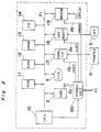
- Fig. 2 depicts a block diagram of the system of Fig. 1.
- a CPU 10 controls the system on the basis of a system program and an application program which are stored in a ROM 11 and a RAM 12, respectively.
- the RAM 12 is backed up at all times by the secondary battery.
- Reference numeral 13 is a VRAM (Video RAM) which develops into a dot pattern various data produced by the aforementioned programs and stores therein display data correspondingly to a display screen of the liquid crystal display unit 3.
- VRAM Video RAM
- Reference numeral 14 is a floppy disc drive unit.
- the keyboard 2 is further provided with a SET-UP key, a SPACE key and a CURSOR key as the keys related to the present invention for setting operating conditions for the computer system.
- the liquid crystal display unit 3 is a large-sized one of a large number of dot segments and is provided with a back light of an EL panel, a cold cathode ray tube or the like.
- Reference numeral 17 is a parallel interface unit, to which the printer 6 is connected, for performing interface control.
- the parallel interface unit 17 may be replaced by a serial interface as occasion demands.
- Reference numeral 18 is a CRT adapter unit which is capable of changing a coloured screen to a monochromatic one or the latter to the former by virtue of unit replacement.
- This adapter unit 18 is the unit for converting digital data produced by the computer system into video signals, for example, composite signals.
- Reference numeral 19 is a MODEM unit which is connected to a telephone circuit and may be replaced through unit replacement by an SIO (serial I/O) for connecting an external MODEM.
- SIO serial I/O
- Reference numeral 20 is a power unit containing therein a secondary battery circuit and a power supply circuit.
- the CPU 10 controls the switching of DC supply lines l3, l4 and l5 connecting the power unit 20 with the parallel interface unit 17, the CRT adapter unit 18 and the MODEM 19, respectively.
- the power unit 20 supplies the above described circuit units with DC power through a DC supply line l2.
- the RAM 12 is always supplied with the DC power irrespective of the condition of a power switch.
- l1 is a bus line for executing data interchange between the CPU 10 and the other units.
- Fig. 3 depicts a switching circuit provided in the power unit 20.
- a latch circuit 30 holds the condition of switching control signals PVCRT, PVMDM and PVPRT supplied from the CPU 10 and is reset by a reset signal at the time of initialization.
- Output terminals of the latch circuit 30 are connected to base terminals of switching transistors Tr1 to Tr3, which are further connected to base terminals of switching transistors Tr4 to Tr6. Upon turning on these transistors Tr4 to Tr6, the DC voltage is supplied to the CRT adapter 18, the MODEM 19 and the parallel interface 17, until the latch circuit 30 is reset or turned off.
- Reference numeral 31 is a power circuit provided with the secondary battery, which is charged by AC power source and outputs the DC voltage.
- the system When the computer body 1 is turned on, the system is set to the initial condition at step s100 on the basis of an initialization processing program previously stored in the ROM 11 and an OS (operating system) program is commenced. Such a condition enables the user program to start or to be formed. In this event, an operator operates the SET-UP key provided on the keyboard 2 to set the operating conditions of the computer body 1 and other devices (step s101).
- step s102 SET-UP menu data are produced on the basis of the system program of the ROM 11 and are developed into a certain dot pattern to be stored in the VRAM 13.
- the data stored in the VRAM 13 are displayed on the liquid crystal display unit 3.
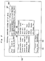
- Fig. 5 the names of the setting items are displayed on the left side and those of newly set condition are displayed on the right side. For example, when time is newly set, an item name "Time" is initially selected using the CURSOR key. The time is then newly set by inputting appropriate condition using the numeral keys and the like.
- the item names related to the present invention are designated by the reference numerals 51, 53, 55 and 57.
- a cursor counter provided in the RAM 12 is renewed at step s106 and the cursor is set on each of the item names.
- Display Mode 51 When the cursor is positioned at "Display Mode 51", the operator can set any one of a monochrome mode, a colour mode and an off mode in which the display 5 is not used.
- any one of a "Parallel” mode, a "Serial” mode and an off mode can be set.
- steps s110 to s112, steps s113 to s115 or steps s116 to s118 are processed so that each menu register may be renewed.
- the aforementioned messages 1 to 3 are then read out in compliance with the register, and are changed and displayed.
- the operator operates an "ENTER" key provided on the keyboard 2 at step s105.
- step s120 the contents of each register are stored in an area for condition establishment which has been determined in advance in the RAM 12.
- the signals PVCRT, PVMDM and PVPRT are supplied to the latch circuit 30 to reset it at step s121, thereby turning on or off the transistors Tr1 to Tr6 to switch the power supply to each control unit.
- the above processes are followed by a data processing routine in which these processes are again performed upon operation of the SET-UP key at step s122.
- the peripheral device or devices to be used are selected on the basis of the SET-UP menu at the time the computer system is powered on. This selection initiates the power supply to the desired devices, thus resulting in effective use of the battery power source.
Landscapes
- Engineering & Computer Science (AREA)
- Theoretical Computer Science (AREA)
- Physics & Mathematics (AREA)
- General Engineering & Computer Science (AREA)
- General Physics & Mathematics (AREA)
- Power Sources (AREA)
Description
- The present invention relates to a method of supplying electric power to one or more peripheral devices in a computer system driven by a battery, and to a computer system utilizing such a method.
- In a personal computer system, a personal computer is generally connected to a plurality of peripheral devices, for example, a CRT display, a MODEM and the like. When such a computer system is driven by an AC power source, there is no problem even if it is supplied with electricity at all times irrespective of its use. In recent years, the personal computer has tended to be formed into a compact size and become portable. Nowadays, there is an increased demand to use the personal computer anywhere, resulting in the necessity of driving the computer system with the use of a battery.
- The conventional computer system is always supplied with electricity irrespective of the use of peripheral devices, since it is generally driven by the AC power source. Even in the computer system driven by the battery, the peripheral devices are always supplied with electricity after the system has been turned on, resulting disadvantageously in unnecessary consumption of the battery.
- EP-A-0 172 344 discloses an arrangement for interrupting the supply of power to devices of a computer system, by means of a user command (whose manner of generation is not specified) in the case of a floating point processor, and by means of an operating system in the case of an external storage device (floppy disc unit/controller) and a modem.
- The present invention has been developed with a view to substantially eliminating the above described disadvantage of unnecessary consumption of battery power, and therefore has for its object to provide a method of controlling device power in a computer system in which a battery power source accommodated within a computer body may be effectively used.
- In one aspect the present invention provides a method of controlling device power in a computer system in which a plurality of peripheral devices connected thereto, externally with respect to the body of a central computer unit, are driven by virtue of a battery power source accommodated within said computer unit body, the method comprising:
generating and displaying SET-UP menu information for setting operating conditions of said devices, said information including a user-operable device selection item;
selecting any of said devices in accordance with said device selection item; and
supplying electric power from said battery power source to the selected device or devices;
said device selection being executed at the time of initial setting after the computer system has been powered ON, each of said devices being at that time powered OFF. - In another aspect, the present invention provides a computer system in which a plurality of peripheral devices connected or connectable thereto, externally with respect to the body of a central computer unit, are adapted to receive power from a battery power source accommodated within said computer unit body, the computer system including means for causing power to be supplied from the battery power source selectively to the or any peripheral device, and means for generating and displaying on a display of the system a menu from which an instruction for selectively powering ON a desired peripheral device can be input by a user, the or each peripheral device being powered OFF when the computer system is initially powered ON.
- According to the invention, since only the or each selected device is supplied with electric power, and since the or each device is powered OFF when the system is initially powered ON, unnecessary consumption of battery power is efficiently prevented.
- An embodiment of the present invention will now be described, by way of example only, with reference to the accompanying drawings, throughout which like parts are designated by like reference numerals, and in which:
- Fig. 1 is a perspective view of a computer system according to an embodiment of the present invention;
- Fig. 2 is a block diagram showing a circuit of the system of Fig. 1;
- Fig. 3 is a circuit diagram of a switching circuit provided in a power unit of the system of Fig. 1;
- Fig. 4 is a flow-chart showing the processing in the system of Fig. 1; and
- Fig. 5 is a view showing an example of the display of SET-UP menu information.
- Referring first to Fig. 1, a computer system according to one preferred embodiment of the present invention includes a portable
personal computer body 1 to which several peripheral devices, for example, aCRT display 5, aprinter 6 and a telephone circuit (not shown) are connected through respective connector cables. Thecomputer body 1 is provided with akeyboard 2, a liquidcrystal display unit 3 and a floppy disc 4 detachably mounted therein. Thekeyboard 2 is provided with a plurality of alphanumeric keys, a function key and the like. - The peripheral devices can be selected by the
keyboard 2 or through software processing so as to be out of operation unless occasion demands. - The
computer body 1 accommodates a control unit for controlling the peripheral devices and is driven by either an AC power source or the secondary battery. - Fig. 2 depicts a block diagram of the system of Fig. 1.
- In the block diagram of Fig. 2, a
CPU 10 controls the system on the basis of a system program and an application program which are stored in aROM 11 and aRAM 12, respectively. TheRAM 12 is backed up at all times by the secondary battery. -
Reference numeral 13 is a VRAM (Video RAM) which develops into a dot pattern various data produced by the aforementioned programs and stores therein display data correspondingly to a display screen of the liquidcrystal display unit 3. -
Reference numeral 14 is a floppy disc drive unit. Thekeyboard 2 is further provided with a SET-UP key, a SPACE key and a CURSOR key as the keys related to the present invention for setting operating conditions for the computer system. - The liquid
crystal display unit 3 is a large-sized one of a large number of dot segments and is provided with a back light of an EL panel, a cold cathode ray tube or the like. -
Reference numeral 17 is a parallel interface unit, to which theprinter 6 is connected, for performing interface control. Theparallel interface unit 17 may be replaced by a serial interface as occasion demands. -
Reference numeral 18 is a CRT adapter unit which is capable of changing a coloured screen to a monochromatic one or the latter to the former by virtue of unit replacement. Thisadapter unit 18 is the unit for converting digital data produced by the computer system into video signals, for example, composite signals. -
Reference numeral 19 is a MODEM unit which is connected to a telephone circuit and may be replaced through unit replacement by an SIO (serial I/O) for connecting an external MODEM. -
Reference numeral 20 is a power unit containing therein a secondary battery circuit and a power supply circuit. TheCPU 10 controls the switching of DC supply lines ℓ3, ℓ4 and ℓ5 connecting thepower unit 20 with theparallel interface unit 17, theCRT adapter unit 18 and theMODEM 19, respectively. Thepower unit 20 supplies the above described circuit units with DC power through a DC supply line ℓ2. TheRAM 12 is always supplied with the DC power irrespective of the condition of a power switch. - ℓ1 is a bus line for executing data interchange between the
CPU 10 and the other units. - Fig. 3 depicts a switching circuit provided in the
power unit 20. Alatch circuit 30 holds the condition of switching control signals PVCRT, PVMDM and PVPRT supplied from theCPU 10 and is reset by a reset signal at the time of initialization. Output terminals of thelatch circuit 30 are connected to base terminals of switching transistors Tr1 to Tr3, which are further connected to base terminals of switching transistors Tr4 to Tr6. Upon turning on these transistors Tr4 to Tr6, the DC voltage is supplied to theCRT adapter 18, theMODEM 19 and theparallel interface 17, until thelatch circuit 30 is reset or turned off. -
Reference numeral 31 is a power circuit provided with the secondary battery, which is charged by AC power source and outputs the DC voltage. - With reference to Fig. 3 and a flow-chart of Fig. 4, the system operation will be explained hereinafter.
- When the
computer body 1 is turned on, the system is set to the initial condition at step s100 on the basis of an initialization processing program previously stored in theROM 11 and an OS (operating system) program is commenced. Such a condition enables the user program to start or to be formed. In this event, an operator operates the SET-UP key provided on thekeyboard 2 to set the operating conditions of thecomputer body 1 and other devices (step s101). - When any key other than this key is operated, the system executes the processing corresponding to the key which has been operated. Upon operation of the SET-UP key, the procedure proceeds to step s102 at which SET-UP menu data are produced on the basis of the system program of the
ROM 11 and are developed into a certain dot pattern to be stored in theVRAM 13. The data stored in theVRAM 13 are displayed on the liquidcrystal display unit 3. - Setting items of each condition are stored in the
RAM 12. These items are decided definitely and displayed as shown in Fig. 5. - In Fig. 5, the names of the setting items are displayed on the left side and those of newly set condition are displayed on the right side. For example, when time is newly set, an item name "Time" is initially selected using the CURSOR key. The time is then newly set by inputting appropriate condition using the numeral keys and the like. The item names related to the present invention are designated by the
reference numerals - Whenever the CURSOR key is operated at step s103, a cursor counter provided in the
RAM 12 is renewed at step s106 and the cursor is set on each of the item names. - When the cursor is positioned at "
Display Mode 51", the operator can set any one of a monochrome mode, a colour mode and an off mode in which thedisplay 5 is not used. - When the cursor is set on "COM1 53" or "
COM2 55" related to the MODEM, the operator can select any one of an internal MODEM, an SIO for application of an external MODEM and an off mode. - Furthermore, when the cursor is set on "
Interface 57", any one of a "Parallel" mode, a "Serial" mode and an off mode can be set. - If each control unit is not accommodated in the
computer body 1, the aforementioned three items are automatically set. - Subsequent to such CURSOR key operations, upon operation of the SPACE key at step s104, the
conditions 1 to 3 are changed according to the number of key operations. - More specifically, steps s110 to s112, steps s113 to s115 or steps s116 to s118 are processed so that each menu register may be renewed. The
aforementioned messages 1 to 3 are then read out in compliance with the register, and are changed and displayed. At the time of completion of the condition establishment, the operator operates an "ENTER" key provided on thekeyboard 2 at step s105. - At step s120, the contents of each register are stored in an area for condition establishment which has been determined in advance in the
RAM 12. - If the setting condition is other than the off mode, the signals PVCRT, PVMDM and PVPRT are supplied to the
latch circuit 30 to reset it at step s121, thereby turning on or off the transistors Tr1 to Tr6 to switch the power supply to each control unit. The above processes are followed by a data processing routine in which these processes are again performed upon operation of the SET-UP key at step s122. - As described above, the peripheral device or devices to be used are selected on the basis of the SET-UP menu at the time the computer system is powered on. This selection initiates the power supply to the desired devices, thus resulting in effective use of the battery power source.
- Although the present invention has been fully described by way of example with reference to the accompanying drawings, it is to be noted here that various changes and modifications will be apparent to those skilled in the art within the scope of the present invention, as defined by the claims.
Claims (2)
- A method of controlling device power in a computer system in which a plurality of peripheral devices (5,6) connected thereto, externally with respect to the body (1) of a central computer unit, are driven by virtue of a battery power source (20) accommodated within said computer unit body (1), the method being characterized by comprising:
generating and displaying SET-UP menu information (50) for setting operating conditions of said devices, said information including a user-operable device selection item;
selecting any of said devices (5,6) in accordance with said device selection item; and
supplying electric power from said battery power source (20) to the selected device or devices (5,6);
said device selection being executed at the time of initial setting after the computer system has been powered ON, each of said devices (5,6) being at that time powered OFF. - A computer system in which a plurality of peripheral devices (5,6) connected thereto, externally with respect to the body (1) of a central computer unit, are adapted to receive power from a battery power source (20) accommodated within said computer unit body (1), the computer system including means (10,30,Tr1-Tr6) for causing power to be supplied from the battery power source (20) selectively to the or any peripheral device (5,6), the system being characterized by comprising means for generating and displaying on a display (3) of the system a SET-UP menu (50) including a user-operable device selection item, means for selecting any of said devices in accordance with said device selection item, and means for selectively powering ON said or each peripheral device selected by a user, the or each peripheral device (5,6) being powered OFF when the computer system is initially powered ON.
Applications Claiming Priority (2)
| Application Number | Priority Date | Filing Date | Title |
|---|---|---|---|
| JP62260192A JPH0650457B2 (en) | 1987-10-14 | 1987-10-14 | Computer system device power controller |
| JP260192/87 | 1987-10-14 |
Publications (3)
| Publication Number | Publication Date |
|---|---|
| EP0317072A2 EP0317072A2 (en) | 1989-05-24 |
| EP0317072A3 EP0317072A3 (en) | 1990-08-08 |
| EP0317072B1 true EP0317072B1 (en) | 1995-01-04 |
Family
ID=17344606
Family Applications (1)
| Application Number | Title | Priority Date | Filing Date |
|---|---|---|---|
| EP88309404A Expired - Lifetime EP0317072B1 (en) | 1987-10-14 | 1988-10-07 | Method and system for controlling power in a computer system |
Country Status (5)
| Country | Link |
|---|---|
| US (1) | US5163124A (en) |
| EP (1) | EP0317072B1 (en) |
| JP (1) | JPH0650457B2 (en) |
| DE (1) | DE3852697T2 (en) |
| HK (1) | HK51996A (en) |
Families Citing this family (46)
| Publication number | Priority date | Publication date | Assignee | Title |
|---|---|---|---|---|
| EP0429780B1 (en) * | 1989-11-29 | 1997-11-12 | Kabushiki Kaisha Toshiba | Computer system capable of connecting an expansion unit |
| JPH03231320A (en) * | 1990-02-06 | 1991-10-15 | Mitsubishi Electric Corp | Microcomputer system |
| EP0443876A3 (en) * | 1990-02-23 | 1992-01-02 | Kabushiki Kaisha Toshiba | Computer system capable of connecting expansion unit |
| US5404542A (en) * | 1990-10-19 | 1995-04-04 | Everex Systems, Inc. | Power line switching circuit with monitor |
| JPH04236682A (en) * | 1991-01-18 | 1992-08-25 | Mitsubishi Electric Corp | Microcomputer system |
| JPH05324139A (en) * | 1992-01-16 | 1993-12-07 | Intel Corp | MCU power-down control method |
| FI94571C (en) * | 1992-03-02 | 1995-09-25 | Icl Personal Systems Oy | Video Display Device |
| US5404543A (en) * | 1992-05-29 | 1995-04-04 | International Business Machines Corporation | Method and system for reducing an amount of power utilized by selecting a lowest power mode from a plurality of power modes |
| US5742514A (en) * | 1992-10-20 | 1998-04-21 | Compaq Computer Corporation | Integrated remote asynchronous power switch |
| US5483656A (en) * | 1993-01-14 | 1996-01-09 | Apple Computer, Inc. | System for managing power consumption of devices coupled to a common bus |
| KR950005216B1 (en) * | 1993-03-31 | 1995-05-22 | 삼성전자주식회사 | Power saving apparatus for pc |
| DE9309641U1 (en) * | 1993-07-02 | 1993-09-09 | Geiss, Andreas, 79669 Zell | Signal-controlled circuit arrangement |
| WO1995006385A1 (en) * | 1993-08-23 | 1995-03-02 | Macronix International Co., Ltd. | Input device interface |
| US5590339A (en) * | 1993-08-23 | 1996-12-31 | Macronix International Co., Ltd. | Input device interface with power connect state and serial data channel enabling power to the device from time to time |
| KR950010952B1 (en) * | 1993-09-08 | 1995-09-26 | 삼성전자주식회사 | Serial communication port and optical communication port transfer controller and method thereof |
| FR2712407B1 (en) * | 1993-11-10 | 1996-03-29 | Mario Garletti | Saving device for controlling the power supply of screens and printers of computer systems during periods of non-use. |
| EP1136907B1 (en) | 1993-12-09 | 2006-04-26 | Canon Kabushiki Kaisha | Information processing apparatus serving as a host unit, and method of controlling an information processing apparatus |
| US5481732A (en) * | 1993-12-14 | 1996-01-02 | Shahbazi; Horyeh D. | CRT monitor power control unit |
| EP0662652B1 (en) * | 1994-01-10 | 2000-07-05 | Sun Microsystems, Inc. | Method and apparatus for reducing power consumption in a computer system |
| KR0130621B1 (en) * | 1994-04-27 | 1998-04-09 | 김광호 | How to save power on electrophotographic printers |
| JP2856675B2 (en) * | 1994-06-27 | 1999-02-10 | 日本電気株式会社 | A wireless selective call receiver having an I/F with a portable information processing device |
| WO1996010781A1 (en) * | 1994-09-30 | 1996-04-11 | Apple Computer, Inc. | Method and apparatus for anticipatory power management for low power pda |
| US5752050A (en) * | 1994-10-04 | 1998-05-12 | Intel Corporation | Method and apparatus for managing power consumption of external devices for personal computers using a power management coordinator |
| US5463261A (en) * | 1994-10-19 | 1995-10-31 | Minnesota Mining And Manufacturing Company | Power conservation device for a peripheral interface module |
| EP0725330A3 (en) * | 1995-01-24 | 1997-03-12 | Hewlett Packard Co | Computer keyboard with power control key |
| KR960030631A (en) * | 1995-01-27 | 1996-08-17 | 김광호 | Energy-saving fax |
| US5596757A (en) * | 1995-02-16 | 1997-01-21 | Simple Technology, Inc. | System and method for selectively providing termination power to a SCSI bus terminator from a host device |
| KR0172003B1 (en) * | 1995-03-28 | 1999-03-30 | 김광호 | Computer system and its control method |
| KR0149263B1 (en) * | 1995-03-31 | 1998-10-15 | 김광호 | Personal computer unified with printer system |
| KR0167648B1 (en) * | 1995-10-10 | 1999-01-15 | 김광호 | Power supply device |
| KR0139545Y1 (en) * | 1995-12-06 | 1999-04-01 | 삼성전자주식회사 | Heater preheater of cathode ray tube |
| US5974552A (en) * | 1995-12-29 | 1999-10-26 | Samsung Electronics Co., Ltd. | Method and apparatus for executing a scheduled operation after wake up from power off state |
| KR100189781B1 (en) * | 1996-05-07 | 1999-06-01 | 윤종용 | Display device and its power supply control method |
| KR970073986A (en) * | 1996-05-15 | 1997-12-10 | 김광호 | Printer power control device and method |
| US5901067A (en) * | 1996-11-15 | 1999-05-04 | Kim Y. Kao | System for interactively selecting and activating groups of electrically powered devices |
| US7143204B1 (en) * | 1996-11-15 | 2006-11-28 | Logiclink Corporation | Method and apparatus for suspending or adjusting billing charge for usage of electrically powered devices if abnormal or halt condition detected |
| KR19980044732A (en) * | 1996-12-07 | 1998-09-05 | 김광호 | Display and Display Method of DPMS Mode in Computer System |
| KR100211801B1 (en) * | 1997-03-12 | 1999-08-02 | 윤종용 | Power control method and apparatus |
| KR100306697B1 (en) | 1998-07-23 | 2001-11-30 | 윤종용 | Portable computer system for controlling the power supply of the universal serial bus and its control method |
| US6735708B2 (en) * | 1999-10-08 | 2004-05-11 | Dell Usa, L.P. | Apparatus and method for a combination personal digital assistant and network portable device |
| JP2002197051A (en) * | 2000-12-11 | 2002-07-12 | Internatl Business Mach Corp <Ibm> | Method for selecting communication adapter for determining communication destination, method for setting communication adapter, computer device, portable information device, and storage medium |
| GB2389200A (en) * | 2002-05-29 | 2003-12-03 | Motorola Inc | Data communication device with user controllable power supply |
| US7069462B2 (en) * | 2003-05-30 | 2006-06-27 | Hewlett-Packard Development Company, L.P. | Operation mode scheduling |
| US20040250147A1 (en) * | 2003-06-03 | 2004-12-09 | Christopher Chang | Uninterrupted system operation |
| TWI266197B (en) * | 2005-04-11 | 2006-11-11 | Wistron Corp | Method for enabling or disabling a peripheral maintaining electrically connected to a computer system |
| TWI584227B (en) * | 2016-09-30 | 2017-05-21 | 晶睿通訊股份有限公司 | Image processing method, image processing device and image processing system |
Family Cites Families (16)
| Publication number | Priority date | Publication date | Assignee | Title |
|---|---|---|---|---|
| GB1536046A (en) * | 1976-06-30 | 1978-12-20 | Ibm | Data processing system power control |
| US4443861A (en) * | 1981-04-13 | 1984-04-17 | Forney Engineering Company | Combined mode supervisory program-panel controller method and apparatus for a process control system |
| US4403303A (en) * | 1981-05-15 | 1983-09-06 | Beehive International | Terminal configuration manager |
| JPS57204930A (en) * | 1981-06-10 | 1982-12-15 | Canon Inc | Electronic apparatus |
| JPS5914028A (en) * | 1982-07-15 | 1984-01-24 | Canon Inc | Method for controlling power supply |
| JPS5955526A (en) * | 1982-09-24 | 1984-03-30 | Sharp Corp | Interface circuit |
| JPS59212930A (en) * | 1983-05-18 | 1984-12-01 | Hitachi Ltd | Terminal-driven power-on control method and control device |
| US4747041A (en) * | 1983-06-27 | 1988-05-24 | Unisys Corporation | Automatic power control system which automatically activates and deactivates power to selected peripheral devices based upon system requirement |
| US4611289A (en) * | 1983-09-29 | 1986-09-09 | Coppola Anthony F | Computer power management system |
| JPS6152722A (en) * | 1984-08-22 | 1986-03-15 | Nippon Data General Kk | Power econimizing system |
| US4677566A (en) * | 1984-10-18 | 1987-06-30 | Burroughs Corporation | Power control network for multiple digital modules |
| US4663539A (en) * | 1984-11-29 | 1987-05-05 | Burroughs Corporation | Local power switching control subsystem |
| JPS61194547A (en) * | 1985-02-23 | 1986-08-28 | Nec Corp | Rewriting method for nonvolatile memory |
| US4674031A (en) * | 1985-10-25 | 1987-06-16 | Cara Corporation | Peripheral power sequencer based on peripheral susceptibility to AC transients |
| JPS62143518A (en) * | 1985-12-18 | 1987-06-26 | Hitachi Micro Comput Eng Ltd | power supply circuit |
| JPS63236113A (en) * | 1987-03-25 | 1988-10-03 | Toshiba Corp | Battery driven portable equipment |
-
1987
- 1987-10-14 JP JP62260192A patent/JPH0650457B2/en not_active Expired - Fee Related
-
1988
- 1988-10-07 DE DE3852697T patent/DE3852697T2/en not_active Expired - Lifetime
- 1988-10-07 EP EP88309404A patent/EP0317072B1/en not_active Expired - Lifetime
-
1991
- 1991-04-15 US US07/685,987 patent/US5163124A/en not_active Expired - Lifetime
-
1996
- 1996-03-21 HK HK51996A patent/HK51996A/en not_active IP Right Cessation
Also Published As
| Publication number | Publication date |
|---|---|
| EP0317072A3 (en) | 1990-08-08 |
| HK51996A (en) | 1996-03-29 |
| US5163124A (en) | 1992-11-10 |
| DE3852697T2 (en) | 1995-07-13 |
| JPH0650457B2 (en) | 1994-06-29 |
| JPH01102611A (en) | 1989-04-20 |
| DE3852697D1 (en) | 1995-02-16 |
| EP0317072A2 (en) | 1989-05-24 |
Similar Documents
| Publication | Publication Date | Title |
|---|---|---|
| US5163124A (en) | Method and apparatus for controlling power to device in a computer system | |
| US5705906A (en) | Robot teaching pendant | |
| US6006335A (en) | Power management system and method of displaying power management information in a computer | |
| JPH08241150A (en) | PMS level display device using hardware cursor in portable computer and method thereof | |
| EP0911799A2 (en) | Display control method and information processing apparatus | |
| US5583539A (en) | Item selection signal input apparatus that reduces the processing load of a host computer | |
| US5297286A (en) | Popup control system for portable computer having setup function and popup function | |
| JPH08272497A (en) | Keyboard device | |
| JPH10320085A (en) | Portable information terminal and method for starting the same | |
| EP0488384A1 (en) | Electric power saving device of a portable data terminal and its method | |
| US6163847A (en) | Computer with automatic power cut-off function and control method therefor | |
| US5428739A (en) | Display control system for setting gray scale levels using popup menu | |
| JP2716684B2 (en) | Multifunctional panel used for robots | |
| JPH0883143A (en) | Pen input device | |
| US5381161A (en) | Data processing apparatus | |
| JP2516347B2 (en) | Control method of word processor | |
| JPH10319920A (en) | Portable electronic devices | |
| JPH0745783Y2 (en) | Computer system start / stop control device | |
| JPH0991253A (en) | Information processing device | |
| JP2001320505A (en) | Communication terminal device | |
| JP2002152866A (en) | Remote control device | |
| JPH10230488A (en) | Robot control method and control device | |
| JPH08314602A (en) | Liquid crystal keyboard | |
| JP2000075966A (en) | Information processing device | |
| JPH054024Y2 (en) |
Legal Events
| Date | Code | Title | Description |
|---|---|---|---|
| PUAI | Public reference made under article 153(3) epc to a published international application that has entered the european phase |
Free format text: ORIGINAL CODE: 0009012 |
|
| AK | Designated contracting states |
Kind code of ref document: A2 Designated state(s): DE GB |
|
| PUAL | Search report despatched |
Free format text: ORIGINAL CODE: 0009013 |
|
| AK | Designated contracting states |
Kind code of ref document: A3 Designated state(s): DE GB |
|
| 17P | Request for examination filed |
Effective date: 19901119 |
|
| 17Q | First examination report despatched |
Effective date: 19930205 |
|
| GRAA | (expected) grant |
Free format text: ORIGINAL CODE: 0009210 |
|
| AK | Designated contracting states |
Kind code of ref document: B1 Designated state(s): DE GB |
|
| REF | Corresponds to: |
Ref document number: 3852697 Country of ref document: DE Date of ref document: 19950216 |
|
| PLBE | No opposition filed within time limit |
Free format text: ORIGINAL CODE: 0009261 |
|
| STAA | Information on the status of an ep patent application or granted ep patent |
Free format text: STATUS: NO OPPOSITION FILED WITHIN TIME LIMIT |
|
| 26N | No opposition filed | ||
| REG | Reference to a national code |
Ref country code: GB Ref legal event code: IF02 |
|
| PGFP | Annual fee paid to national office [announced via postgrant information from national office to epo] |
Ref country code: DE Payment date: 20071004 Year of fee payment: 20 |
|
| PGFP | Annual fee paid to national office [announced via postgrant information from national office to epo] |
Ref country code: GB Payment date: 20071003 Year of fee payment: 20 |
|
| REG | Reference to a national code |
Ref country code: GB Ref legal event code: PE20 Expiry date: 20081006 |
|
| PG25 | Lapsed in a contracting state [announced via postgrant information from national office to epo] |
Ref country code: GB Free format text: LAPSE BECAUSE OF EXPIRATION OF PROTECTION Effective date: 20081006 |