EP0317017A2 - High definition television augmentation channel - Google Patents
High definition television augmentation channel Download PDFInfo
- Publication number
- EP0317017A2 EP0317017A2 EP88202548A EP88202548A EP0317017A2 EP 0317017 A2 EP0317017 A2 EP 0317017A2 EP 88202548 A EP88202548 A EP 88202548A EP 88202548 A EP88202548 A EP 88202548A EP 0317017 A2 EP0317017 A2 EP 0317017A2
- Authority
- EP
- European Patent Office
- Prior art keywords
- digital data
- data streams
- signals
- coupled
- multiplicity
- Prior art date
- Legal status (The legal status is an assumption and is not a legal conclusion. Google has not performed a legal analysis and makes no representation as to the accuracy of the status listed.)
- Granted
Links
Images


Classifications
-
- H—ELECTRICITY
- H04—ELECTRIC COMMUNICATION TECHNIQUE
- H04N—PICTORIAL COMMUNICATION, e.g. TELEVISION
- H04N7/00—Television systems
- H04N7/015—High-definition television systems
-
- H—ELECTRICITY
- H04—ELECTRIC COMMUNICATION TECHNIQUE
- H04N—PICTORIAL COMMUNICATION, e.g. TELEVISION
- H04N21/00—Selective content distribution, e.g. interactive television or video on demand [VOD]
- H04N21/20—Servers specifically adapted for the distribution of content, e.g. VOD servers; Operations thereof
- H04N21/23—Processing of content or additional data; Elementary server operations; Server middleware
- H04N21/238—Interfacing the downstream path of the transmission network, e.g. adapting the transmission rate of a video stream to network bandwidth; Processing of multiplex streams
- H04N21/2383—Channel coding or modulation of digital bit-stream, e.g. QPSK modulation
-
- H—ELECTRICITY
- H04—ELECTRIC COMMUNICATION TECHNIQUE
- H04N—PICTORIAL COMMUNICATION, e.g. TELEVISION
- H04N11/00—Colour television systems
- H04N11/24—High-definition television systems
- H04N11/26—High-definition television systems involving two-channel transmission
-
- H—ELECTRICITY
- H04—ELECTRIC COMMUNICATION TECHNIQUE
- H04N—PICTORIAL COMMUNICATION, e.g. TELEVISION
- H04N19/00—Methods or arrangements for coding, decoding, compressing or decompressing digital video signals
-
- H—ELECTRICITY
- H04—ELECTRIC COMMUNICATION TECHNIQUE
- H04N—PICTORIAL COMMUNICATION, e.g. TELEVISION
- H04N21/00—Selective content distribution, e.g. interactive television or video on demand [VOD]
- H04N21/40—Client devices specifically adapted for the reception of or interaction with content, e.g. set-top-box [STB]; Operations thereof
- H04N21/43—Processing of content or additional data, e.g. demultiplexing additional data from a digital video stream; Elementary client operations, e.g. monitoring of home network or synchronising decoder's clock; Client middleware
- H04N21/438—Interfacing the downstream path of the transmission network originating from a server, e.g. retrieving MPEG packets from an IP network
- H04N21/4382—Demodulation or channel decoding, e.g. QPSK demodulation
-
- H—ELECTRICITY
- H04—ELECTRIC COMMUNICATION TECHNIQUE
- H04N—PICTORIAL COMMUNICATION, e.g. TELEVISION
- H04N7/00—Television systems
- H04N7/08—Systems for the simultaneous or sequential transmission of more than one television signal, e.g. additional information signals, the signals occupying wholly or partially the same frequency band, e.g. by time division
Landscapes
- Engineering & Computer Science (AREA)
- Multimedia (AREA)
- Signal Processing (AREA)
- Television Systems (AREA)
- Compression Or Coding Systems Of Tv Signals (AREA)
- Digital Transmission Methods That Use Modulated Carrier Waves (AREA)
- Transmission Systems Not Characterized By The Medium Used For Transmission (AREA)
Abstract
Description
- The invention pertains to television information transmission and reception and more particularly to the transmission and reception of high definition television information.
- Conventional color television systems transmit picture information at a rate of 59.94 picture fields per second, two constituting a frame, each frame consisting of 525 horizontal scan lines. To reduce the transmission and reception bandwidths required to reproduce the transmitted picture, these horizontal scan lines are interlaced from field-to-field with a ratio of two-to-one, that is only every other scan line is transmitted in each field. Scan lines omitted in one field are transmitted in the next succeeding field, thus all the odd numbered fields contain one set of scan lines and the even numbered fields contain the set of scan lines which interlace with the scan lines in the odd numbered fields. This arrangement permits the transmission, reception, and picture reproduction at bandwidths reduced from that required for every scan line to be transmitted in each field.
- Television pictures reproduced in these conventional systems have aspect ratio of four to three, i.e. for every four units of horizontal width there are three units of vertical height. Thus, a
picture tube 15 inches on the diagonal has a width of 12 inches and a height of 9 inches, while apicture tube 19 inches on the diagonal has a width of 15.2 inches and a height of 11.4 inches. - The above specifications provide television pictures of good commercial quality which, however, degrade as the size of the picture tube increases. The graininess of the picture produced by the 2:1 interlace ratio is acceptable for small screen receivers, but becomes more apparent as the size of the picture tube increases. Consequently, as the television screen continue to increase in size the graininess becomes increasingly more unacceptable. To counteract this and provide greater picture resolution high definition television systems having increased aspect ratios and 1:1 progressive scans are presently under consideration.
- In accordance with the principle of the present invention, digital data encoded from RGB high definition television signals are coupled to bit rate reducing circuitry wherein they are converted to digital signals at bit rates that are reduced from the bit rates of the input digital signals. The digital signals at the reduced bit rates are then coupled to a multiplexer which sequentially positions the input data and provides a multiplicity of digital data streams having equal bit rates. The equal bit rate data streams are then coupled to modulating circuitry, employing spread spectrum techniques, to modulate a carrier signal for transmission.
- At a receiver the modulated carrier is demodulated and the equal bit rate data streams are reestablished. The equal bit rate data streams are then coupled to a demultiplexer where they are sequentially positioned and rearranged to provide the bit rate reduced data streams which are then coupled to a decoder, wherefrom digital data streams emerge that are representative of the digital data streams coupled to the input terminal of the transmitter.
-
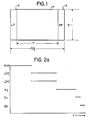
- Figure 1 is a representation of an augmented television picture screen showing thereon the left panel, the center panel, and the right panel.
- Figure 2 is a block diagram of a transmitter of a preferred embodiment of the invention.
- Figure 2a is a diagram showing the allocation of time to encoded signals over a four scan line interval.
- Figure 2b is a block diagram of the transmitter of Figure 2 showing various bit rates of signals in the transmitter.
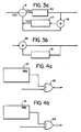
- Figure 3a is a diagram of a differential pulse code modulator encoder.
- Figure 3b is a block diagram of a differential pulse code modulator decoder.
- Figure 4a is a diagram of a direct sequence encoder.
- Figure 4b is a diagram of a direct sequence decoder.
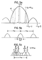
- Figures 5a, 5b, and 5c are spectral representations of finite pulse sequences useful in explaining the invention.
- Figure 6 is a block diagram of a receiver of a preferred embodiment of the invention.
- In a high definition television system there is a 1:1 sequential transmission of the scan lines in each frame and the frames are transmitted at a 59.94 Hz rate, in contrast to the 2:1 interlacing of fields which are transmitted at a 59.94 Hz rate on conventional television transmission. In addition, the aspect ratio of the picture is increased from 4:3 to 5.33:3 as shown in Figure 1, wherein the center panel 11 is representative of the conventional TV picture, while the left panel (LP) 12 and right panel (RP) 13 are added to increase the aspect ratio as shown in the Figure. The total scan time for each scan line remains constant from frame-to-frame, as does scan time allotted to the center panel, and the total scan time allotted to the left and right panels. Though the total scan time allotted to the left and right panels remains constant from frame-to-frame the distribution of this allotted time may vary from frame-to-frame depending upon the position of the center panel. The high definition television (HDTV) source signals provide the RGB color components with a 525 line progressive scan, a frame rate of 59.94 Hz, 16:9 aspect ratio, and a 16.8 MHz horizontal bandwidth for luminance. As shown in Figure 2, these source signals and a synchronisation signal S are coupled to a
HDTV encoder 15, which may be the encoder disclosed by Cavallerano, et al in co-pending U.S. Patent Application Serial Number 122,148, filed November 17, 1987, entitled "High Definition NTSC Compatible Television System with Increased Horizontal Bandwidth and Reduced Color Artifacts", (PHA 21,411). This application is hereby incorporated by reference into the present application. TheHDTV encoder 15 processes the source signals and provides a sum of the left panel data and the right panel data on anoutput 17, two line differential (LD) encoding signals, which are derived from every four source lines, onoutputs output 23, and the chrominance signals (Ih, Qh) onoutputs HDTV encoder 15. - Signals at the output terminals of the HDTV encoder are coupled to a bit
rate reduction unit 29 in the transmitter wherein each stream of digital data is converted to an analog signal in digital to analog (D/A) converters 31a through 31f. Analog signals established from the data streams atoutputs low pass filters 33a-c, while luminance and chrominance analog signals derived from the data streams atoutputs filters 33d-f as baseband signals after being down converted inmixers 35a-c operating at a local oscillator (LO) frequency, an internally generated frequency for conversion purposes, its frequency value depending on and varying with the channel to be received or transmitted. Thelow pass filters 33a-f remove extraneous frequencies and serve as anti-aliasing filters for the reconversion of the analog signals to digital signals by the analog to digital (A/D)converters 37a-f wherefrom digital signals emerge at bit rates reduced from that of the bit rates at the output terminals of theHDTV encoder 15. These bit rates, as well as reduced bit rates mentioned below can be found in Fig. 2b. Additional bit rate reduction is achieved by coupling the reduced bit rate data streams from the A/D converters to differentialpulse code modulators 39a-f (DPCM) wherefrom a digital signal representative of the difference between the actual digital data sample and a predicted sample for that data is provided. - Each input value V(i) to the DPCM is compared with a predicted value V(p) which is based on the history of the input data. This history is accumulated over many cycles of the highly redundant video image and may be provided in three dimensions; two spatial and one temporal. For example, pixel values in the horizontal and vertical directions and corresponding values from consecutive frames are combined to yield the initial value V(p). DPCM systems and the generation of predictive values are taught in the article "DPCM Picture Coding With Adaptive Prediction" IEEE Transactions on Communications, No. 11, Nov. 1977, by Wilmut Zschunke, predictors being discussed on page 1295. This article is incorporated by reference into the present application. The difference V(d) between V(i) and V(p) is provided by a
difference circuit 41 and coupled to anon-linear quantizer 43 shown in Figure 3a. Non-linearquantizer 43 has a non-linear input-output characteristic and a limited number of output values. This non-linear characteristic is based on the human eye's greater sensitivity to luminance/chrominance errors in fields exhibiting small or no changes in luminance/chrominance, than it is to errors in fields exhibiting large luminance/chrominance changes. The number and size of the quantitization steps are made functions of the value V(d), each increasing with the value of V(d). The output of thequantizer 43 is coupled to the output terminal of DPCM and to asum circuit 45 wherein it is added to the previous predicted value from an n-dimensional predictor 47 and the sum, so produced, provided to thepredictor 47 as a new prediction value. - Figure 3b is a diagram of a circuit for recovering the actual digital sample value from the differential value. DPCM data is coupled to a
sum circuit 49 wherein it is added to the previously determined predicted value in an n-dimensional predictor 51. Sums resulting from this addition are coupled to the output terminal of the decoder and to thepredictor 51 as an updated prediction. - Turning back now to Figure 2, six data streams with varying bit rates and mutually exclusive time intervals, with the exception of the data streams representative of the LD2 and the LD4 data from
HDTV encoder 15 are coupled from thebit rate reducer 29 to a multiplexer/buffer memory 53. After a suitable delay of either the LD2 or LD4 data stream to provide a totality of mutually exclusive time intervals the data bit streams are sequentially stored in the memory of the multiplexer/buffer memory 53 wherein they are divided into N data streams of equal length and equal bit rate which are respectively and simultaneously coupled to N direct sequence encoders (DSE) 55-1 to 55-N. - A modulo-2 addition is performed on the low bit-rate streams by the DSE to provide a code sequence at a predetermined increased bit rate for each of the data streams emanating from the multiplexer/
buffer memory 53. A circuit for accomplishing this bit rate conversion is shown in Figure 4a. A pseudo-noise sequence generator 57 (PNSG) having a sequence rating at the desired conversion bit rate is coupled to one terminal of an exclusive ORgate 59, the other terminal of which is coupled to receive the data stream. Exclusive ORgate 59 provides an encoded data stream at a bit rate determined by the bit rate of the pseudonoise sequence generator 59. Only a small percentage of the possible codes that may be generated by the PNSG are utilized to achieve a code repetition rate equal to the TV frame repetition rate. Each code has a defined start point synchronized to the TV frame start. Of all the possible codes available from thePNSG 57 only N codes are choses and their start points are defined such that each source bit to be transmitted is represented by a unique sequence within the repetition time of the code sequences. For a 200K bit/sec data rate, as in a preferred embodiment of the invention, a 6M bit/sec rate for the sequencing bits may, for example, be adopted thus establishing an appreciable overhead to allow for an optimum selection of sequences. - Extracting the initial data stream from the encoded data stream may be accomplished with the same circuitry, this time acting as a direct sequence decoder (DSD), as shown in Figure 4b. In this figure a PNSG 61 is coupled to one input terminal of an exclusive OR
gate 63, the other terminal of which is coupled to receive the encoded data stream.PNSG 61 is in synchronism with the encoded data stream thereby providing the original data stream at the output terminal of exclusive ORgate 63. - Turning back again to Figure 2, to provide minimum sidelobes for the transmitted signals the N coded data streams at the PNSG bit rate are combined in pairs and provided at an intermediate frequency (IF) spectrum by minimum shift key (MSK) modulators 65-1 through 65-N/2. These MSK modulators provide a sequence of pulses at the intermediate frequency which constitute the coded signals. These signals are not infinite sequences, existing only for a small fraction of a frame time. Signals of this type exhibit spectral lobes within a sin(x)/x envelope determined by the width of the pulses in the sequence. Such a spectrum is represented in Figures 5a and 5b. If the width of the pulses within the sequence is equal to T, the nulls of the sin(x)/x are at frequencies spaced from the center frequency equal to the reciprocal of the pulse width. Spectral lobes within the envelope have frequency spacing that are equal to the repetition rate of the pulses of the sequence, as shown in Figure 5b, which is an expanded view of the
area 67 in Figure 5a. The width of these lobes is a function of the number of pulses in the sequence and the repetition rate and is equal to twice the repetition rate divided by the number of pulses plus one. Though not shown in the Figure each spectral lobe has a number of side lobes associated therewith. - Each MSK modulator uses a different modulation carrier frequency. If the initial frequency is equal to K times the repetition frequency and each succeeding frequency is displaced from this initial frequency by i/(N+1) f(rep) is should be apparent that when i equals N the gap between two spectral lobes will be filled as illustrated in Figure 5c. A
summation network 69 is coupled to the output terminals of the MSK modulators to receive modulated signals and provide the summation thereof to amixer 71 wherein they are converted and coupled via abandpass filter 73 for transmission. - The combination of direct sequence encoding and minimum shift key modulation establishes a noise like spectral distribution for the radiated signal, spreading the signal energy over a relatively wide band of frequencies. This spread spectrum radiation has a very low power spectral density which would be deep in the noise of analog detectors operating in a finite band. Consequently these signals may radiate in the VHF and UHF taboo bands and not interfere with analog transmissions in these bands.
- Referring to Figure 6 the transmitted signal is received and heterodyned in
mixer 75 operating at a local oscillator (LO) frequency and passed throughband pass filter 77 to a bank of MSK demodulators 79-1 through 79-N/2. Each of these demodulators operates at a demodulation carrier frequency corresponding to a modulation carrier frequency used in the transmitter. As a result, N nearly identical baseband spectrum are generated. Each baseband signal is coupled to an associated comb filter in a bank of comb filters 81-1 through 81-N to suppress unwanted and unnecessary spectral components and improve interchannel isolation. These filtered signals are then coupled to N direct sequence decoders (DSD) 83-1 through 83-N to restore the original equal length equal bit rate data streams. A clock signal for the different DS decoders is provided byinput 82, and synchronization for this decoding is provided onsynchronisation signal connection 85 from the main channel TV signal. Each equal length, equal bit rate data stream is coupled to a demultiplexer/buffer memory 87 wherein the demultiplexing operation reestablishes the original six DPCM encoded signals. Decoding of the DPCM encoded signals is accomplished indecoders 89a through 89f as previously described with reference to Figure 3b. Reestablishment of the high definition TV coded signals continues with the digital to analog (D/A) conversion of the decoded DPCM signals in digital to analog converters 91a through 91f. The enhancement signals, in analog form, corresponding to LD2, LD4, and the left and right panel enhancement signals are coupled throughlow pass filters 93a-93c, converted to digital signals in analog to digital converters (A/D) 95a - 95c whereat the left and right panel encoded signals have been reestablished. The LD2 and LD4 are further processed by time compressing these digital signals by 4:3 incompressors 97a-97b. - The analog luminance and chrominance signals are frequency shifted in
mixers 99a - 99c, bandpass filtered in filters 101a - 101c, converted to digital signals in analog to digital (A/D)converters 95d - 95f wherefrom reestablished encoded luminance and chrominance signals are provided. - Finally, all signals are coupled to a
HDTV decoder 103 which provides RGB signals suitable for display on a display device (not shown). - While the invention has been described in its preferred embodiments it is to be understood that the words which have been used are words of description rather than of limitation and the changes within the purview of the appended claims may be made without departure from the true scope and spirit of the invention in its broader aspects.
Claims (10)
bit rate reducing means coupled to receive said digital data streams at predetermined bit rates for providing converted digital data streams at bit rates reduced from said predetermined bit rates;
means coupled to said bit rate reducing means for sequentially positioning said converted digital data streams and providing a multiplicity of converted digital data streams having equal bit rates; and
means coupled to said sequentially positioning means for modulating said multiplicity of converted digital data streams on a carrier signal for transmission.
means for receiving and demodulating said carrier signal to correspondingly provide said multiplicity of digital data streams at a multiplicity of output terminals;
means coupled to said demodulating means for sequentially positioning said digital data streams and providing a plurality of digital data signals at a plurality of bit rates; and
means coupled to said sequentially positioning means for processing said plurality of digital data signals to provide signals representative of said digital data signals coupled to said input terminals of said transmitter.
a multiplicity of direct sequence decoders coupled respectively to receive said demodulated signals and provide said multiplicity of digital data streams at output terminals thereof.
reducing said predetermined bit rates to provide data streams at reduced bit rates;
positioning said digital data streams at reduced bit rates to form a sequential arrangement of digital data streams;
forming a multiplicity of equal length, equal bit rate digital data streams from said sequential arrangement of digital data streams; and
modulating said equal length, equal bit rate digital streams on to a carrier for transmission.
Applications Claiming Priority (2)
| Application Number | Priority Date | Filing Date | Title |
|---|---|---|---|
| US123031 | 1987-11-19 | ||
| US07/123,031 US4890283A (en) | 1987-11-19 | 1987-11-19 | High definition television augmentation channel |
Publications (3)
| Publication Number | Publication Date |
|---|---|
| EP0317017A2 true EP0317017A2 (en) | 1989-05-24 |
| EP0317017A3 EP0317017A3 (en) | 1991-01-30 |
| EP0317017B1 EP0317017B1 (en) | 1994-03-09 |
Family
ID=22406339
Family Applications (1)
| Application Number | Title | Priority Date | Filing Date |
|---|---|---|---|
| EP88202548A Expired - Lifetime EP0317017B1 (en) | 1987-11-19 | 1988-11-15 | High definition television augmentation channel |
Country Status (8)
| Country | Link |
|---|---|
| US (1) | US4890283A (en) |
| EP (1) | EP0317017B1 (en) |
| JP (1) | JP2912959B2 (en) |
| KR (1) | KR970000760B1 (en) |
| CA (1) | CA1321014C (en) |
| DE (1) | DE3888292T2 (en) |
| HK (1) | HK62696A (en) |
| MX (1) | MX164815B (en) |
Cited By (3)
| Publication number | Priority date | Publication date | Assignee | Title |
|---|---|---|---|---|
| EP0400756A2 (en) * | 1989-06-02 | 1990-12-05 | Koninklijke Philips Electronics N.V. | Method and apparatus for digitally processing a high definition television augmentation signal |
| WO1992007442A1 (en) * | 1990-10-19 | 1992-04-30 | Zenith Electronics Corporation | Co-channel interference reduction system for digital high definition television |
| US5179442A (en) * | 1989-06-02 | 1993-01-12 | North American Philips Corporation | Method and apparatus for digitally processing a high definition television augmentation signal |
Families Citing this family (19)
| Publication number | Priority date | Publication date | Assignee | Title |
|---|---|---|---|---|
| IT1230235B (en) * | 1989-06-07 | 1991-10-18 | Telettra Spa | STRUCTURING AND PACKAGE TRANSMISSION OF THE INFORMATION GENERATED BY CODER FOR VIDEO SIGNALS. |
| US5270110A (en) * | 1990-07-19 | 1993-12-14 | Dow Corning Toray Silicon Co., Ltd. | Film-forming organopolysiloxane composition |
| JP2994699B2 (en) * | 1990-07-19 | 1999-12-27 | 東レ・ダウコーニング・シリコーン株式会社 | Film-forming organopolysiloxane composition |
| US5151783A (en) * | 1991-06-05 | 1992-09-29 | Faroudja Y C | Digital television with enhancement |
| US5127021A (en) * | 1991-07-12 | 1992-06-30 | Schreiber William F | Spread spectrum television transmission |
| US5243629A (en) * | 1991-09-03 | 1993-09-07 | At&T Bell Laboratories | Multi-subcarrier modulation for hdtv transmission |
| JPH0568243A (en) * | 1991-09-09 | 1993-03-19 | Hitachi Ltd | Variable length coding controlling system |
| US5425050A (en) * | 1992-10-23 | 1995-06-13 | Massachusetts Institute Of Technology | Television transmission system using spread spectrum and orthogonal frequency-division multiplex |
| US5311543A (en) * | 1992-10-23 | 1994-05-10 | Schreiber William F | Television transmission system using two stages of spead-spectrum processing |
| JPH06189345A (en) * | 1992-12-22 | 1994-07-08 | Matsushita Electric Ind Co Ltd | Hdtv signal transmitter |
| US5577042A (en) * | 1994-01-18 | 1996-11-19 | Mcgraw Broadcast | Broadcast and presentation system and method |
| US5729570A (en) * | 1994-12-08 | 1998-03-17 | Stanford Telecommunications, Inc. | Orthogonal code division multiple access communication system having multicarrier modulation |
| US5579341A (en) * | 1994-12-29 | 1996-11-26 | Motorola, Inc. | Multi-channel digital transceiver and method |
| US6678311B2 (en) | 1996-05-28 | 2004-01-13 | Qualcomm Incorporated | High data CDMA wireless communication system using variable sized channel codes |
| JP3745459B2 (en) * | 1996-07-18 | 2006-02-15 | 富士通株式会社 | Communication method and communication apparatus for wireless LAN system |
| US5859664A (en) * | 1997-01-31 | 1999-01-12 | Ericsson Inc. | Method and apparatus for line or frame-synchronous frequency hopping of video transmissions |
| US5894498A (en) * | 1997-02-26 | 1999-04-13 | Motorola, Inc. | Method and apparatus for analyzing a composite carrier signal |
| JP2000092461A (en) * | 1998-09-10 | 2000-03-31 | Sony Corp | Additional information superimposing method and video signal output device |
| CA2642666C (en) * | 2006-02-13 | 2019-09-10 | Vividas Technologies Pty Ltd | Method, system and software product for streaming content |
Citations (1)
| Publication number | Priority date | Publication date | Assignee | Title |
|---|---|---|---|---|
| US4613903A (en) * | 1984-04-06 | 1986-09-23 | North American Philips Corporation | High-resolution television transmission system |
Family Cites Families (4)
| Publication number | Priority date | Publication date | Assignee | Title |
|---|---|---|---|---|
| US2905756A (en) * | 1956-11-30 | 1959-09-22 | Bell Telephone Labor Inc | Method and apparatus for reducing television bandwidth |
| US3707680A (en) * | 1970-05-20 | 1972-12-26 | Communications Satellite Corp | Digital differential pulse code modulation system |
| DE3248687A1 (en) * | 1982-12-30 | 1984-07-05 | Siemens AG, 1000 Berlin und 8000 München | Switchable colour television signal coder/decoder |
| US4551867A (en) * | 1983-11-04 | 1985-11-12 | Joseph Gurevich | Toilet bowl which washes |
-
1987
- 1987-11-19 US US07/123,031 patent/US4890283A/en not_active Expired - Lifetime
-
1988
- 1988-11-09 MX MX13713A patent/MX164815B/en unknown
- 1988-11-15 DE DE3888292T patent/DE3888292T2/en not_active Expired - Fee Related
- 1988-11-15 EP EP88202548A patent/EP0317017B1/en not_active Expired - Lifetime
- 1988-11-16 KR KR1019880015050A patent/KR970000760B1/en not_active IP Right Cessation
- 1988-11-16 CA CA000583197A patent/CA1321014C/en not_active Expired - Fee Related
- 1988-11-18 JP JP63290301A patent/JP2912959B2/en not_active Expired - Lifetime
-
1996
- 1996-04-11 HK HK62696A patent/HK62696A/en not_active IP Right Cessation
Patent Citations (1)
| Publication number | Priority date | Publication date | Assignee | Title |
|---|---|---|---|---|
| US4613903A (en) * | 1984-04-06 | 1986-09-23 | North American Philips Corporation | High-resolution television transmission system |
Non-Patent Citations (1)
| Title |
|---|
| IEEE TRANSACTIONS ON COMMUNICATIONS. vol. 25, no. 11, November 1977, NEW YORK US pages 1295 - 1302; Willmut Zschunke: "DPCM Picture Coding With Adaptive Prediction" * |
Cited By (4)
| Publication number | Priority date | Publication date | Assignee | Title |
|---|---|---|---|---|
| EP0400756A2 (en) * | 1989-06-02 | 1990-12-05 | Koninklijke Philips Electronics N.V. | Method and apparatus for digitally processing a high definition television augmentation signal |
| EP0400756A3 (en) * | 1989-06-02 | 1992-01-22 | Koninklijke Philips Electronics N.V. | Method and apparatus for digitally processing a high definition television augmentation signal |
| US5179442A (en) * | 1989-06-02 | 1993-01-12 | North American Philips Corporation | Method and apparatus for digitally processing a high definition television augmentation signal |
| WO1992007442A1 (en) * | 1990-10-19 | 1992-04-30 | Zenith Electronics Corporation | Co-channel interference reduction system for digital high definition television |
Also Published As
| Publication number | Publication date |
|---|---|
| HK62696A (en) | 1996-04-19 |
| CA1321014C (en) | 1993-08-03 |
| KR890009185A (en) | 1989-07-15 |
| JP2912959B2 (en) | 1999-06-28 |
| US4890283A (en) | 1989-12-26 |
| EP0317017A3 (en) | 1991-01-30 |
| DE3888292T2 (en) | 1994-09-29 |
| MX164815B (en) | 1992-09-25 |
| EP0317017B1 (en) | 1994-03-09 |
| JPH01198840A (en) | 1989-08-10 |
| KR970000760B1 (en) | 1997-01-18 |
| DE3888292D1 (en) | 1994-04-14 |
Similar Documents
| Publication | Publication Date | Title |
|---|---|---|
| EP0317017B1 (en) | High definition television augmentation channel | |
| US5086340A (en) | Co-channel interference reduction system for digital high definition television | |
| RU2141173C1 (en) | Screen indication device for digital video signal processing system | |
| RU2146854C1 (en) | Screen indication device for digital video signal processing system | |
| US5543939A (en) | Video telephone systems | |
| US4661862A (en) | Differential PCM video transmission system employing horizontally offset five pixel groups and delta signals having plural non-linear encoding functions | |
| US4654696A (en) | Video signal format | |
| EP0499088B1 (en) | Method and apparatus for communicating compressed digital video signals using multiple processors | |
| US4931855A (en) | Method for generating and transmitting high-definition color television signals, compatible with current standards and process and apparatus for receiving said signals | |
| US4631574A (en) | Compatible high-definition television with extended aspect ratio | |
| US4989091A (en) | Scan converter for a high definition television system | |
| US5159453A (en) | Video processing method and apparatus | |
| US4967272A (en) | Bandwidth reduction and multiplexing of multiple component TV signals | |
| US6784917B1 (en) | Digital broadcasting system | |
| US4630099A (en) | Time multiplexing chrominance information for compatible high-definition television | |
| US4683490A (en) | Video signal processing apparatus | |
| Yamamoto et al. | 30 Mbit/s codec for the NTSC color TV signal using an interfield-intrafield adaptive prediction | |
| US5247351A (en) | High definition television system compatible with NTSC system | |
| CA1161158A (en) | Digital television transmission using chrominance inversion | |
| Sawada et al. | 32 Mbit/s transmission of NTSC color TV signals by composite DPCM coding | |
| US2860186A (en) | Television transmission channel sharing system | |
| US4661840A (en) | NTSC color television transmission | |
| GB2145610A (en) | Television transmission systems | |
| JPS59219083A (en) | Television picture signal transmission system | |
| JPH01302990A (en) | Method and apparatus for signal transmission |
Legal Events
| Date | Code | Title | Description |
|---|---|---|---|
| PUAI | Public reference made under article 153(3) epc to a published international application that has entered the european phase |
Free format text: ORIGINAL CODE: 0009012 |
|
| AK | Designated contracting states |
Kind code of ref document: A2 Designated state(s): DE FR GB |
|
| PUAL | Search report despatched |
Free format text: ORIGINAL CODE: 0009013 |
|
| AK | Designated contracting states |
Kind code of ref document: A3 Designated state(s): DE FR GB |
|
| 17P | Request for examination filed |
Effective date: 19910725 |
|
| 17Q | First examination report despatched |
Effective date: 19930505 |
|
| GRAA | (expected) grant |
Free format text: ORIGINAL CODE: 0009210 |
|
| AK | Designated contracting states |
Kind code of ref document: B1 Designated state(s): DE FR GB |
|
| REF | Corresponds to: |
Ref document number: 3888292 Country of ref document: DE Date of ref document: 19940414 |
|
| ET | Fr: translation filed | ||
| PLBE | No opposition filed within time limit |
Free format text: ORIGINAL CODE: 0009261 |
|
| STAA | Information on the status of an ep patent application or granted ep patent |
Free format text: STATUS: NO OPPOSITION FILED WITHIN TIME LIMIT |
|
| 26N | No opposition filed | ||
| REG | Reference to a national code |
Ref country code: FR Ref legal event code: CD |
|
| REG | Reference to a national code |
Ref country code: FR Ref legal event code: CD |
|
| REG | Reference to a national code |
Ref country code: GB Ref legal event code: IF02 |
|
| REG | Reference to a national code |
Ref country code: GB Ref legal event code: 746 Effective date: 20020917 |
|
| REG | Reference to a national code |
Ref country code: FR Ref legal event code: D6 |
|
| PGFP | Annual fee paid to national office [announced via postgrant information from national office to epo] |
Ref country code: GB Payment date: 20061127 Year of fee payment: 19 |
|
| PGFP | Annual fee paid to national office [announced via postgrant information from national office to epo] |
Ref country code: FR Payment date: 20061129 Year of fee payment: 19 |
|
| PGFP | Annual fee paid to national office [announced via postgrant information from national office to epo] |
Ref country code: DE Payment date: 20070110 Year of fee payment: 19 |
|
| GBPC | Gb: european patent ceased through non-payment of renewal fee |
Effective date: 20071115 |
|
| PG25 | Lapsed in a contracting state [announced via postgrant information from national office to epo] |
Ref country code: DE Free format text: LAPSE BECAUSE OF NON-PAYMENT OF DUE FEES Effective date: 20080603 |
|
| REG | Reference to a national code |
Ref country code: FR Ref legal event code: ST Effective date: 20080930 |
|
| PG25 | Lapsed in a contracting state [announced via postgrant information from national office to epo] |
Ref country code: GB Free format text: LAPSE BECAUSE OF NON-PAYMENT OF DUE FEES Effective date: 20071115 |
|
| PG25 | Lapsed in a contracting state [announced via postgrant information from national office to epo] |
Ref country code: FR Free format text: LAPSE BECAUSE OF NON-PAYMENT OF DUE FEES Effective date: 20071130 |