EP0316898B1 - Anpassung der Anhängekupplung - Google Patents
Anpassung der Anhängekupplung Download PDFInfo
- Publication number
- EP0316898B1 EP0316898B1 EP88119099A EP88119099A EP0316898B1 EP 0316898 B1 EP0316898 B1 EP 0316898B1 EP 88119099 A EP88119099 A EP 88119099A EP 88119099 A EP88119099 A EP 88119099A EP 0316898 B1 EP0316898 B1 EP 0316898B1
- Authority
- EP
- European Patent Office
- Prior art keywords
- end portions
- hitch
- aligned
- sets
- holes
- Prior art date
- Legal status (The legal status is an assumption and is not a legal conclusion. Google has not performed a legal analysis and makes no representation as to the accuracy of the status listed.)
- Expired - Lifetime
Links
- 230000005540 biological transmission Effects 0.000 description 3
- 230000000712 assembly Effects 0.000 description 1
- 238000000429 assembly Methods 0.000 description 1
- 238000006243 chemical reaction Methods 0.000 description 1
- 238000010276 construction Methods 0.000 description 1
- 230000000694 effects Effects 0.000 description 1
- 238000000034 method Methods 0.000 description 1
Images
Classifications
-
- B—PERFORMING OPERATIONS; TRANSPORTING
- B60—VEHICLES IN GENERAL
- B60K—ARRANGEMENT OR MOUNTING OF PROPULSION UNITS OR OF TRANSMISSIONS IN VEHICLES; ARRANGEMENT OR MOUNTING OF PLURAL DIVERSE PRIME-MOVERS IN VEHICLES; AUXILIARY DRIVES FOR VEHICLES; INSTRUMENTATION OR DASHBOARDS FOR VEHICLES; ARRANGEMENTS IN CONNECTION WITH COOLING, AIR INTAKE, GAS EXHAUST OR FUEL SUPPLY OF PROPULSION UNITS IN VEHICLES
- B60K17/00—Arrangement or mounting of transmissions in vehicles
- B60K17/28—Arrangement or mounting of transmissions in vehicles characterised by arrangement, location, or type of power take-off
-
- A—HUMAN NECESSITIES
- A01—AGRICULTURE; FORESTRY; ANIMAL HUSBANDRY; HUNTING; TRAPPING; FISHING
- A01B—SOIL WORKING IN AGRICULTURE OR FORESTRY; PARTS, DETAILS, OR ACCESSORIES OF AGRICULTURAL MACHINES OR IMPLEMENTS, IN GENERAL
- A01B71/00—Construction or arrangement of setting or adjusting mechanisms, of implement or tool drive or of power take-off; Means for protecting parts against dust, or the like; Adapting machine elements to or for agricultural purposes
- A01B71/06—Special adaptations of coupling means between power take-off and transmission shaft to the implement or machine
- A01B71/066—Special adaptations of coupling means between power take-off and transmission shaft to the implement or machine for enabling pitch, roll or yaw movements of trailed implements or machines
Definitions
- the present invention relates to a hitch adapter for the optional connection either directly to tractor three-point hitch links or to a quick coupler carried by the three-point hitch links comprising a mast structure defined by upper end portions, a pair of divergent central portions and spaced lower end portions parallel to the upper end portions wherein the upper end portions contain a connecting means and wherein the lower end portions contain aligned forward and rearward connecting means.
- This implement hitch (US-A-3 151 883) is intended for the connection of an implement to a tractor that can be provided with a variety of hitch systems including a three-point hitch or a three-point hitch together with a so called quick coupler. If the implement is not powered variations in the distance between the towing tractor and the implement which are the result of using or not using a quick coupler are not critical. However, when the implement needs to be powered by a power shaft coupled to a tractor power take-off shaft it is necessary to use different length power shafts to go from a tractor with a quick coupler (or long three-points hitch links) to a tractor without a quick coupler.
- the object of the present invention is to overcome or reduce the problem with a reasonably simple apparatus.
- the connecting means of the upper end portions and the rearward connecting means of the lower end portions are located in a transverse and upright plane, a central member arranged to be positionable between a first position and a second out-of-the-way position is connected in the first position to the connecting means of the upper end portions such that a portion of the central member is projecting forwardly and further means are provided to connect the forwardly projecting portion of the central member in the first position to the upper three-point hitch link.
- the hitch adapter connected to an implement remains always in its relative position to a tractor no matter whether the hitch structure of the tractor makes use of a quick coupler or not, as the lower end portions have sets of forward and rearward connection means in the form of pin receiving holes, of which appropriate ones may be respectively selected for attachment directly to lower three-point hitch links or to a quick coupler.
- the central member is projecting forwardly in its first position for an attachment directly to the three-point hitch upper link.
- the second position of the central member is an out-of-the-way position in which the central member projects rearwardly or is removed completely for permitting attachment of the upper end portions of the hitch adapter to the upper hook of the quick coupler.
- the forwardly and rearwardly located attachment points maintain constant the spacing of the hitch adapter from the tractor (no matter whether a quick coupler is mounted on the three-point hitch or not) and a single shaft can be used.
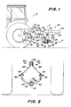
- the implement 20 includes a forwardly extending tongue 22 defined by a box beam 24 having a hitch member 26 depending therefrom and including, at its bottom end, a forwardly extending hitch structure 28 carrying a ball connector 30.
- An upper gearbox or housing 32 of a transmission assembly 34 is fixed to the forward end of the box beam 24 and supports a lower gearbox or housing 36 for rotation about an upright axis Y which passes through the ball connector 30 and is vertical when the implement tongue 22 is held in an elevated, normal working position by the three-point hitch 12.
- An input shaft 38 of the transmission assembly 34 is supported in the lower gearbox 36 and is coupled to the tractor power take-off shaft 18 by a telescopic drive or power shaft 40 having universal joints at its opposite ends for permitting relative movement between the tractor 10 and implement 20.
- a hitch adapter 42 includes a fore-and-aft extending drawbar 44 secured to a central portion of a bowed, downwardly and rearwardly extending cross member 45 and being located approximately at the same level as a tractor drawbar 46 when the tongue 22 is in its normal working position and including an upright stud 48 received in the ball connector 30.
- a storage stand 49 in the form of a bent plate is fixed to the bottom of the drawbar 44 and serves as a down stop, for preventing the three-point hitch 12 from being lowered to the extent that the U-joints embodied in the drive shaft 40 operate at undesirable angles, and serves to support the implement on the ground when the tractor hitch arrangement is disconnected from the hitch adapter 42.
- Fixed to the top of the drawbar 44 and to the rear of the cross member 45 and forming part of a steering assembly 50 is a guide member 52 having a cylindrical guide surface 54 arranged concentrically about an axis X passing through the ball connector 30 and intersecting the axis Y.
- the steering assembly 50 further includes a pair of steering arms 56 formed of angle members and fixed to opposite sides of the lower gearbox 36 so as to depend therefrom in vertical relationship to the axis X and with opposite inner faces thereof engaged with diametrically opposite surface portions of the cylindrical guide surface 54.
- the steering assembly 50 acts in response to turning movement of the hitch adapter 42 about the axis Y to turn correspondingly the lower gearbox 36 to maintain a desired parallel relationship between the input shaft 38 and PTO shaft 18 but does not act to effect any movement of the gearbox 36 when the tractor 10 rolls about the ball connector 30 relative to the implement 20.
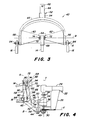
- the hitch adapter 42 is specially constructed so that the implement 20 may be coupled to tractors equipped with hitch arrangements including three-point hitch links of various lengths used either alone, as shown in Figs. 1-3, or together with a quick coupler 58, as shown in Fig. 4, without requiring different lengths of drive shafts 40 to be used with different hitch arrangements.
- the hitch adapter 42 includes an upright mast structure defined by right and left legs 60 and 62 having central, downwardly diverging portions extending between and joined to parallel, spaced upper end portions 64 and parallel, spaced lower end portions 66, each defining a downwardly opening channel.
- the upper end of the hitch adapter 42 is defined by a forwardly projecting central member in the form of an inverted, U-shaped channel member 68 which is substantially square in side view and includes in its pair of arms a set of three mounting holes 70 arranged at consecutive corners of the member 68 such that lines connecting the holes form a right, isosceles triangle.
- the channel member 68 is received between the leg upper end portions 64 and is fixed thereto by upper and lower fastener or connecting means 72 and 74 respectively received in the rearmost pair of the sets of holes 70 and in alternative upper sets of quick hitch mounting holes provided in the leg upper end portions in axial alignment with the rearmost pair of the sets of holes 70.
- the upper three-point hitch link 14 has its rear end received between forward portions of opposite sides of the channel member 68 and contains a hole which receives a fastener means in the form of a pin 80 located in a set of upper link mounting holes 82 provided in the channel member.
- the lower pair of links 16 have their respective rear ends located beside the channels defined by the leg lower end portions 66 and each contains a hole which receives a pin 84 located in a set of lower link mounting holes or connecting means located in the portions 66 in a forward, vertical transverse plane A extending through the set of upper link mounting holes 82.
- a lower set of conneting means in the form of of quick hitch mounting holes 88 is located in each of the leg lower portions 66 behind the lower link mounting holes in a rear, vertical transverse plane B extending through the alternative upper sets of quick hitch mounting holes 70 containing the fastener means 72 and 74.
- the hitch adapter 42 is coupled to the quick coupler 58.
- the quick coupler 58 is shown somewhat schematically but is of a construction similar to that disclosed in US-A-4,415,175, for example.
- the quick coupler 58 includes an inverted, U-shaped framework defined by an upper cross member 90 having legs 92 joined to opposite ends thereof. Located centrally between opposite ends of the cross member 90 and extending rearwardly therefrom is an upwardly opening, upper hook 94.
- Each of the legs 92 has a lower end defined by a rearwardly extending, upwardly opening hook 96.
- the hooks 94 and 96 have respective pin receptacles located in the rear vertical transverse plane B.
- a set of upper link mounting holes receiving the pin 80 and connecting the upper link 14 to the quick coupler, and a pair of lower link mounting holes, receiving the pins 84 and connecting the lower links 16 to the quick coupler.
- the quick coupler 58 shown in Fig. 4 is a standard size, such as a category II quick coupler, for example, and the upper hook 94 thereof extends between the adapter legs 60 and 62 and is engaged with the lower fastener means 74, which in this case would be a pin.
- the upper hook of the quick coupler would be engaged with the upper fastener means 72, which in this case would be in the form of a pin while the lower fastener means 74 would be in the form of a pair of bolt assemblies that are spaced to permit the upper hook to move therebetween toward and away from engagement with the upper fastener means 72.
- the lower hooks 96 of the quick coupler are in latched engagement with pins 98 received in the quick hitch mounting holes 88.
- the hitch adapter 42 can be converted from its configuration (Fig. 1) for attachment directly to three-point hitch links to a configuration (Fig. 4) for attachment to a quick coupler by removing the upper fastener means 72, loosening the lower fastener means 74, if necessary, and pivoting the channel member 68 ninety degrees clockwise or rearwardly to an out-of-the-way position wherein the unused hole 70 in Fig. 1 is matched with the upper set of holes contained in the leg upper end portions 68. The upper fastener means 72 is then replaced. Complete removal of the channel member 68 is an alternative to the above conversion procedure; however, such removal might result in the channel member 68 becoming misplaced or otherwise not readily available for use should it be desired to reconnect the hitch adapter for direct connection to three-point hitch links.
- the mounting holes provided in the hitch adapter 42 in the rearward vertical plane B may be used to mount the hitch adapter to a three-point hitch having longer links than the links 14 and 16 without varying the spacing between the tractor power take-off shaft 18 and the implement transmission input shaft 38.
- the hitch adapter 42 may be used with various combinations of tractor hitch arrangements without necessitating any change in the length of the drive shaft or line 40.
Landscapes
- Engineering & Computer Science (AREA)
- Life Sciences & Earth Sciences (AREA)
- Mechanical Engineering (AREA)
- Soil Sciences (AREA)
- Environmental Sciences (AREA)
- Chemical & Material Sciences (AREA)
- Combustion & Propulsion (AREA)
- Transportation (AREA)
- Agricultural Machines (AREA)
Claims (10)
- Kupplungszwischenstück für die wahlweise Verbindung entweder unmittelbar mit den Lenkern (14, 16) einer Schlepperdreipunktgerätekupplung oder mit einem Schnellkuppler (58), der von den Lenkern (14, 16) der Dreipunktgerätekupplung getragen wird, mit einem Mastaufbau, der durch obere Endteile (64), einem Paar divergierender Zentralabschnitte und gegenseitigen Abstand aufweisende untere Endteile (66), die parallel zu den oberen Endteilen (64) verlaufen, bestimmt ist, wobei die oberen Endteile (64) ein Verbindungsmittel (72, 74) und die unteren Endteile (66) zueinander ausgerichtete vordere und rückwärtige Verbindungsmittel (88) enthalten, gekennzeichnet
dadurch, daß das Verbindungsmittel (72, 74) der oberen Endteile (64) und das rückwärtige Verbindungsmittel (88) der unteren Endteile (66) in einer quer gerichteten und hochstehenden Ebene (B) angeordnet sind;
durch einen Zentralteil (68), der so gestaltet ist, um zwischen einer ersten Stellung und einer Ausdemwegstellung in Stellung bringbar zu sein, und der in der ersten Stellung mit dem Verbindungsmittel (72, 74) der oberen Endteile (64) derart verbunden ist, daß ein Teil des Zentralteils (68) nach vorne vorsteht; und
durch weitere Mittel zum Verbinden des nach vorne vorstehenden Teils des Zentralteils (68) in der ersten Stellung mit dem oberen Lenker (14) der Dreipunktgerätekupplung. - Kupplungszwischenstück nach Anspruch 1, dadurch gekennzeichnet, daß der obere Zentralteil (68) zwischen den genannten Stellungen verschwenkbar ist.
- Kupplungszwischenstück nach Anspruch 1 oder 2, dadurch gekennzeichnet, daß der obere Zentralteil einen U-förmigen Kanal (68) enthält.
- Kupplungszwischenstück nach Anspruch 3, dadurch gekennzeichnet, daß der U-förmige Kanal (68) sich von den oberen Endteilen (64) nach rückwärts erstreckt, wenn er sich in der zweiten Stellung befindet.
- Kupplungszwischenstück nach irgendeinem der vorhergehenden Ansprüche, dadurch gekennzeichnet, daß die oberen Endteile (64) obere und untere Sätze von Befestigungslöchern, die in der genannten hochstehenden Ebene (B) angeordnet sind, enthalten, der Kanalteil (68) mit einem Paar Arme, wobei das genannte Paar Arme erste, zweite, dritte und vierte Sätze von zueinander ausgerichteten Befestigungslöchern (70, 82) aufweist, versehen ist und daß der Kanalteil (68) mit den oberen Endteilen (64) über Befestigungsmittel (72, 74) in der genannten ersten und zweiten Stellung verbindbar ist, wobei, wenn er sich in der ersten Stellung befindet, die genannten ersten und zweiten Sätze von zueinander ausgerichteten Befestigungslöchern (70) zu den genannten oberen und unteren Sätzen von Befestigungslöchern entsprechend ausgerichtet sind und sich obere und untere Befestigungsmittel (72, 74) durch diese zueinander ausgerichteten Löcher (70) erstrecken und wobei, wenn er sich in der zweiten Stellung befindet, die genannten ersten und dritten Sätze von zueinander ausgerichteten Befestigungslöchern (70) zu den genannten oberen und unteren Sätzen von Befestigungslöchern entsprechend ausgerichtet sind und sich die genannten oberen und unteren Befestigungsmittel (72, 74) durch diese zueinander ausgerichteten Löcher erstrecken.
- Kupplungszwischenstück nach Anspruch 5, dadurch gekennzeichnet, daß, wenn er sich in der ersten Stellung befindet, der vierte Satz von zueinander ausgerichteten Löchern (82) des Kanalteils (68) so gestaltet ist, um vorne vor den genannten Endteilen (64) zu liegen zu kommen, sich ein Befestigungsmittel (80) durch diesen Satz von zueinander ausgerichteten Löchern (82) für eine Verbindung mit dem oberen Lenker (14) der Dreipunktgerätekupplung erstreckt und daß der vierte Satz von zueinander ausgerichteten Löchern (82) in einer zweiten quer verlaufenden hochstehenden Ebene (A), die durch die vorderen Verbindungsmittel der unteren Endteile (66) verläuft, angeordnet ist.
- Kupplungszwischenstück nach Anspruch 5, dadurch gekennzeichnet, daß, wenn er sich in seiner ersten Stellung befindet, der dritte Satz von zueinander ausgerichteten Löchern (70) des Kanalteils (68) so gestaltet ist, um vor der genannten ersten quer verlaufenden hochstehenden Ebene (B), die durch die rückwärtigen Verbindungsmittel (88) der unteren Endteile verläuft, zu liegen zu kommen und daß, wenn er sich in seiner zweiten Stellung befindet, die zweiten und vierten Sätze von zueinander ausgerichteten Löchern (70, 82) rückwärtig der genannten ersten Ebene (B) gelegen sind.
- Kupplungszwischenstück nach Anspruch 5, dadurch gekennzeichnet, daß der U-förmige Kanalteil (68) von der Seite gesehen im wesentlichen quadratisch mit einer ersten Seite des Quadrats, die, wenn er sich in seiner ersten Stellung befindet, im Bereich entsprechender Rückseiten der genannten oberen Endteile (64) zu liegen kommt, und mit einer zweiten an die erste Seite angrenzenden Seite ausgebildet ist, die, wenn er sich in seiner zweiten Stellung befindet, im Bereich entsprechender vorderer Kanten der genannten oberen Endteile (64) zu liegen kommt.
- Kupplungszwischenstück nach Anspruch 5, dadurch gekennzeichnet, daß die ersten, zweiten und dritten Sätze von Löchern (70) in einer ein rechtwinkliges, gleichschenkliges Dreieck formenden Art angeordnet sind .
- Kupplungszwischenstück nach Anspruch 9, dadurch gekennzeichnet, daß die ersten, zweiten und dritten Sätze von Löchern (70) im Bereich von aufeinanderfolgenden Ecken des U-förmigen Kanalteils (68) angeordnet sind.
Applications Claiming Priority (2)
| Application Number | Priority Date | Filing Date | Title |
|---|---|---|---|
| US07/123,624 US4776606A (en) | 1987-11-20 | 1987-11-20 | Hitch and drive structure for pto-driven, semi-integral implement |
| US123624 | 1993-09-17 |
Publications (3)
| Publication Number | Publication Date |
|---|---|
| EP0316898A2 EP0316898A2 (de) | 1989-05-24 |
| EP0316898A3 EP0316898A3 (en) | 1990-08-22 |
| EP0316898B1 true EP0316898B1 (de) | 1993-08-25 |
Family
ID=22409789
Family Applications (1)
| Application Number | Title | Priority Date | Filing Date |
|---|---|---|---|
| EP88119099A Expired - Lifetime EP0316898B1 (de) | 1987-11-20 | 1988-11-17 | Anpassung der Anhängekupplung |
Country Status (4)
| Country | Link |
|---|---|
| US (1) | US4776606A (de) |
| EP (1) | EP0316898B1 (de) |
| CA (1) | CA1295872C (de) |
| DE (1) | DE3883486T2 (de) |
Families Citing this family (11)
| Publication number | Priority date | Publication date | Assignee | Title |
|---|---|---|---|---|
| DE19608579C2 (de) * | 1996-03-06 | 1999-03-04 | Deere & Co | Anhängevorrichtung |
| GB2326137A (en) * | 1997-06-06 | 1998-12-16 | New Holland Uk Ltd | Cab suspension for an agricultural vehicle |
| US5816339A (en) * | 1997-06-27 | 1998-10-06 | Deere & Company | Implement swivel hitch for use with a quick-coupler |
| US6119789A (en) * | 1997-08-27 | 2000-09-19 | Durand-Wayland, Inc. | Implement tracking hitch |
| US6412570B1 (en) | 2001-02-16 | 2002-07-02 | Agco Corporation | Draw bar swivel hitch |
| US7204318B2 (en) * | 2002-07-26 | 2007-04-17 | Durand-Wayland, Inc. | Tracking hitch assembly utilizing tractor lift arms as stabilizers |
| US7055618B2 (en) | 2004-06-17 | 2006-06-06 | Cnh America Llc | Hydraulic pump drive |
| CA2887974C (en) * | 2014-05-22 | 2016-12-06 | Agco Corporation | Swivel drawbar hitch mechanism for pull-type implement |
| AT517765B1 (de) * | 2015-10-13 | 2017-07-15 | Ing Scharmüller Josef | Kupplungselement |
| KR102520899B1 (ko) * | 2020-12-30 | 2023-04-11 | 남기성 | 수평으로 길이가 조절되는 트랙터용 3점식 퀵히치 어댑터 |
| KR102535733B1 (ko) * | 2021-01-12 | 2023-05-23 | 남기성 | 수평으로 길이가 조절되는 트랙터용 3점식 퀵히치 어댑터 |
Family Cites Families (11)
| Publication number | Priority date | Publication date | Assignee | Title |
|---|---|---|---|---|
| US3048228A (en) * | 1960-05-18 | 1962-08-07 | Deere & Co | Hitch device |
| US3093394A (en) * | 1961-01-03 | 1963-06-11 | Deere & Co | Convertible hitch |
| US3151883A (en) * | 1962-08-14 | 1964-10-06 | Clifton F Stuart | Implement hitch |
| DK111780B (da) * | 1964-04-01 | 1968-10-07 | R Knaapi | Hurtigkobling til kobling af en arbejdsmaskine til en traktor. |
| US3450220A (en) * | 1967-04-04 | 1969-06-17 | Jack W Frandsen | Automatic drawbar hitch |
| US3472528A (en) * | 1967-10-26 | 1969-10-14 | Massey Ferguson Inc | Convertible category implement tractor hitch |
| FR1590121A (de) * | 1968-06-28 | 1970-04-13 | ||
| GB1426050A (en) * | 1972-11-22 | 1976-02-25 | Shelton P A | Tractor linkage |
| US4431207A (en) * | 1981-12-30 | 1984-02-14 | Westendorf Manufacturing Company, Inc. | Automatic hitch device |
| US4415175A (en) * | 1982-06-23 | 1983-11-15 | Deere & Company | Coupler latch mechanism with a self-opening feature |
| CA1279500C (en) * | 1986-11-06 | 1991-01-29 | Roger Dale Stephenson | Implement hitch adaptor and transmission assembly for allowing towing tractor to turn sharply |
-
1987
- 1987-11-20 US US07/123,624 patent/US4776606A/en not_active Expired - Lifetime
-
1988
- 1988-05-18 CA CA000567107A patent/CA1295872C/en not_active Expired - Lifetime
- 1988-11-17 EP EP88119099A patent/EP0316898B1/de not_active Expired - Lifetime
- 1988-11-17 DE DE88119099T patent/DE3883486T2/de not_active Expired - Fee Related
Also Published As
| Publication number | Publication date |
|---|---|
| DE3883486D1 (de) | 1993-09-30 |
| CA1295872C (en) | 1992-02-18 |
| EP0316898A2 (de) | 1989-05-24 |
| US4776606A (en) | 1988-10-11 |
| DE3883486T2 (de) | 1994-04-14 |
| EP0316898A3 (en) | 1990-08-22 |
Similar Documents
| Publication | Publication Date | Title |
|---|---|---|
| EP0316900B1 (de) | Anhängekupplung | |
| US5706901A (en) | Swivel hitch adaptable for use with either a tractor drawbar or two-point hitch | |
| CA1279500C (en) | Implement hitch adaptor and transmission assembly for allowing towing tractor to turn sharply | |
| US3557892A (en) | Hitch adapter | |
| CA2426630C (en) | Pivoting implement hitch extension | |
| US4776606A (en) | Hitch and drive structure for pto-driven, semi-integral implement | |
| US6755589B2 (en) | Clevis assembly for an implement hitch | |
| US4793430A (en) | Hitch and drive structure for PTO-driven, semi-integral implement | |
| CA2225661C (en) | Implement swivel hitch for use with a quick-coupler | |
| US3058280A (en) | Gang hitch for lawn mowers or the like | |
| US6119789A (en) | Implement tracking hitch | |
| US5957475A (en) | Offset hitch for use in towing an implement | |
| US5265403A (en) | Draft tongue for connecting PTO-driven implement to draft links of a towing vehicle | |
| US7048070B2 (en) | Quick coupler assembly with dual hook members | |
| US11997938B2 (en) | Articulated apparatus for towing a rotary driven implement from a towing vehicle | |
| US20090039615A1 (en) | Adapter for a quick-connect tractor hitch | |
| US5873228A (en) | Shredder for plants | |
| EP0163380A1 (de) | Trägeranordnung für eine angetriebene Einrichtung im Gebrauch mit Traktor und Anhänger | |
| US3177639A (en) | Rotary mower with an aligned and an offset mast-type hitch | |
| US2726589A (en) | Hitch stabilizer | |
| US6390490B1 (en) | Quick connect tractor hitch coupling | |
| US2910816A (en) | Hitching device | |
| US2092584A (en) | Implement coupling means on tractors | |
| US3923322A (en) | Tractor hitch adapter | |
| GB2171884A (en) | Hitching arrangement for an implement pulled by a tractor |
Legal Events
| Date | Code | Title | Description |
|---|---|---|---|
| PUAI | Public reference made under article 153(3) epc to a published international application that has entered the european phase |
Free format text: ORIGINAL CODE: 0009012 |
|
| AK | Designated contracting states |
Kind code of ref document: A2 Designated state(s): DE ES FR GB NL SE |
|
| 17P | Request for examination filed |
Effective date: 19891107 |
|
| PUAL | Search report despatched |
Free format text: ORIGINAL CODE: 0009013 |
|
| RHK1 | Main classification (correction) |
Ipc: A01B 59/043 |
|
| AK | Designated contracting states |
Kind code of ref document: A3 Designated state(s): DE ES FR GB NL SE |
|
| 17Q | First examination report despatched |
Effective date: 19920609 |
|
| GRAA | (expected) grant |
Free format text: ORIGINAL CODE: 0009210 |
|
| AK | Designated contracting states |
Kind code of ref document: B1 Designated state(s): DE ES FR GB NL SE |
|
| PG25 | Lapsed in a contracting state [announced via postgrant information from national office to epo] |
Ref country code: SE Effective date: 19930825 Ref country code: NL Effective date: 19930825 Ref country code: FR Effective date: 19930825 Ref country code: ES Free format text: THE PATENT HAS BEEN ANNULLED BY A DECISION OF A NATIONAL AUTHORITY Effective date: 19930825 |
|
| REF | Corresponds to: |
Ref document number: 3883486 Country of ref document: DE Date of ref document: 19930930 |
|
| PG25 | Lapsed in a contracting state [announced via postgrant information from national office to epo] |
Ref country code: GB Effective date: 19931125 |
|
| EN | Fr: translation not filed | ||
| NLV1 | Nl: lapsed or annulled due to failure to fulfill the requirements of art. 29p and 29m of the patents act | ||
| PLBE | No opposition filed within time limit |
Free format text: ORIGINAL CODE: 0009261 |
|
| STAA | Information on the status of an ep patent application or granted ep patent |
Free format text: STATUS: NO OPPOSITION FILED WITHIN TIME LIMIT |
|
| GBPC | Gb: european patent ceased through non-payment of renewal fee |
Effective date: 19931125 |
|
| 26N | No opposition filed | ||
| PGFP | Annual fee paid to national office [announced via postgrant information from national office to epo] |
Ref country code: DE Payment date: 20011208 Year of fee payment: 14 |
|
| PG25 | Lapsed in a contracting state [announced via postgrant information from national office to epo] |
Ref country code: DE Free format text: LAPSE BECAUSE OF NON-PAYMENT OF DUE FEES Effective date: 20030603 |