EP0316626A1 - Electrochemical cell - Google Patents
Electrochemical cell Download PDFInfo
- Publication number
- EP0316626A1 EP0316626A1 EP88117802A EP88117802A EP0316626A1 EP 0316626 A1 EP0316626 A1 EP 0316626A1 EP 88117802 A EP88117802 A EP 88117802A EP 88117802 A EP88117802 A EP 88117802A EP 0316626 A1 EP0316626 A1 EP 0316626A1
- Authority
- EP
- European Patent Office
- Prior art keywords
- cell
- electrochemical cell
- water
- liquid
- evaporated
- Prior art date
- Legal status (The legal status is an assumption and is not a legal conclusion. Google has not performed a legal analysis and makes no representation as to the accuracy of the status listed.)
- Granted
Links
Images


Classifications
-
- H—ELECTRICITY
- H01—ELECTRIC ELEMENTS
- H01M—PROCESSES OR MEANS, e.g. BATTERIES, FOR THE DIRECT CONVERSION OF CHEMICAL ENERGY INTO ELECTRICAL ENERGY
- H01M8/00—Fuel cells; Manufacture thereof
- H01M8/04—Auxiliary arrangements, e.g. for control of pressure or for circulation of fluids
- H01M8/04007—Auxiliary arrangements, e.g. for control of pressure or for circulation of fluids related to heat exchange
-
- C—CHEMISTRY; METALLURGY
- C25—ELECTROLYTIC OR ELECTROPHORETIC PROCESSES; APPARATUS THEREFOR
- C25B—ELECTROLYTIC OR ELECTROPHORETIC PROCESSES FOR THE PRODUCTION OF COMPOUNDS OR NON-METALS; APPARATUS THEREFOR
- C25B15/00—Operating or servicing cells
-
- H—ELECTRICITY
- H01—ELECTRIC ELEMENTS
- H01M—PROCESSES OR MEANS, e.g. BATTERIES, FOR THE DIRECT CONVERSION OF CHEMICAL ENERGY INTO ELECTRICAL ENERGY
- H01M8/00—Fuel cells; Manufacture thereof
- H01M8/04—Auxiliary arrangements, e.g. for control of pressure or for circulation of fluids
- H01M8/04082—Arrangements for control of reactant parameters, e.g. pressure or concentration
- H01M8/04089—Arrangements for control of reactant parameters, e.g. pressure or concentration of gaseous reactants
- H01M8/04119—Arrangements for control of reactant parameters, e.g. pressure or concentration of gaseous reactants with simultaneous supply or evacuation of electrolyte; Humidifying or dehumidifying
-
- H—ELECTRICITY
- H01—ELECTRIC ELEMENTS
- H01M—PROCESSES OR MEANS, e.g. BATTERIES, FOR THE DIRECT CONVERSION OF CHEMICAL ENERGY INTO ELECTRICAL ENERGY
- H01M2300/00—Electrolytes
- H01M2300/0017—Non-aqueous electrolytes
- H01M2300/0065—Solid electrolytes
- H01M2300/0082—Organic polymers
-
- H—ELECTRICITY
- H01—ELECTRIC ELEMENTS
- H01M—PROCESSES OR MEANS, e.g. BATTERIES, FOR THE DIRECT CONVERSION OF CHEMICAL ENERGY INTO ELECTRICAL ENERGY
- H01M8/00—Fuel cells; Manufacture thereof
- H01M8/04—Auxiliary arrangements, e.g. for control of pressure or for circulation of fluids
- H01M8/04082—Arrangements for control of reactant parameters, e.g. pressure or concentration
- H01M8/04089—Arrangements for control of reactant parameters, e.g. pressure or concentration of gaseous reactants
- H01M8/04119—Arrangements for control of reactant parameters, e.g. pressure or concentration of gaseous reactants with simultaneous supply or evacuation of electrolyte; Humidifying or dehumidifying
- H01M8/04156—Arrangements for control of reactant parameters, e.g. pressure or concentration of gaseous reactants with simultaneous supply or evacuation of electrolyte; Humidifying or dehumidifying with product water removal
-
- H—ELECTRICITY
- H01—ELECTRIC ELEMENTS
- H01M—PROCESSES OR MEANS, e.g. BATTERIES, FOR THE DIRECT CONVERSION OF CHEMICAL ENERGY INTO ELECTRICAL ENERGY
- H01M8/00—Fuel cells; Manufacture thereof
- H01M8/04—Auxiliary arrangements, e.g. for control of pressure or for circulation of fluids
- H01M8/04291—Arrangements for managing water in solid electrolyte fuel cell systems
-
- Y—GENERAL TAGGING OF NEW TECHNOLOGICAL DEVELOPMENTS; GENERAL TAGGING OF CROSS-SECTIONAL TECHNOLOGIES SPANNING OVER SEVERAL SECTIONS OF THE IPC; TECHNICAL SUBJECTS COVERED BY FORMER USPC CROSS-REFERENCE ART COLLECTIONS [XRACs] AND DIGESTS
- Y02—TECHNOLOGIES OR APPLICATIONS FOR MITIGATION OR ADAPTATION AGAINST CLIMATE CHANGE
- Y02E—REDUCTION OF GREENHOUSE GAS [GHG] EMISSIONS, RELATED TO ENERGY GENERATION, TRANSMISSION OR DISTRIBUTION
- Y02E60/00—Enabling technologies; Technologies with a potential or indirect contribution to GHG emissions mitigation
- Y02E60/30—Hydrogen technology
- Y02E60/50—Fuel cells
Definitions
- the invention relates to an electrochemical cell with immobile electrolyte, in particular for use in aviation and space travel.
- the energy conversion in electrochemical cells has an efficiency that is usually well below 100%. For example, it is in alkaline H2 / O2 fuel cells depending on the current density and electrode catalyst between 50 and 60%, based on the upper calorific value of hydrogen. The remaining 40 to 50% of the energy is lost as thermal energy. This thermal energy must be removed from the cells to ensure constant operating conditions and to prevent thermal destruction of the cells.
- electrochemical cells which are constructed according to the principle described above: - Alkaline H2 / O2 fuel cells with a KOH electrolyte defined in a matrix (D. Stachewski in Hydrogen Energy Progress, Vol. 4, Pergamon Press 1983, pp. 1677-1684), - SPE fuel cells with an ion exchange membrane as electrolytes (K.Kordesch, fuel batteries, Springer Verlag 1984, p. 177 ff.), - alkaline water electrolysers with a KOH electrolyte defined in a matrix (FHShubert, Alkaline regenerative fuel cell systems for energy storage, 16 th. Intersoc. Energy conv. Eng. Conf. Atlanta 1981) and - SPE water electrolysers with an ion exchange membrane (S. Stucki et al., Journal Elektrochemical Soc. 1985, p. 367 ff.).
- the invention has for its object to develop an electrochemical cell with immobile electrolyte, which has a much lighter and more compact design than known models.
- a liquid for example treated water
- the liquid is evaporated in the cell.
- the evaporation energy about 2.25 kJ / g for water, is extracted from the cell.
- the steam produced is removed from the cell via a gas stream, for example an excess of reaction gas, and, if necessary, can be condensed in an external cooler.
- the electrochemical cell with evaporative cooling has a number of decisive advantages.
- the structure of the cell becomes simpler and more compact. This significantly reduces the weight.
- the weight advantage compared to a cell with cooling plates is of the order of 20%.
- No cooling circuit is required for the cell.
- the elimination of a coolant pump increases the overall efficiency of the system, since no energy is used for the pump.
- the simpler design and the elimination of the cooling circuit make the system more reliable and easier to maintain.
- Evaporation cooling with water is much more effective than cooling via plate heat exchangers due to the high evaporation heat of approx.2.25 kJ / g.
- the water vapor generated during evaporative cooling can also be used to control the water balance of the electrochemical process. Water is consumed during the electrolysis and must be added to the electrolyte. This can be ideally combined with evaporative cooling. The higher the current density, the more water has to be added to the electrolyte. At the same time, however, the efficiency deteriorates and the cooling must be increased, so more water must be evaporated.
- water is formed as a reaction product that has to be removed via the gas phase in the immobile system, but drying out of the electrolyte (matrix, membrane) by the H2 or O2 gas flows can very easily occur. This drying out is prevented by moistening the gas streams and / or the matrix, as happens with evaporative cooling.
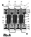
- Figure 1 shows the principle of an immobile H2 / O2 fuel cell 2, which is cooled via water aerosols.
- About Ver care channels 4 and 6 in the cell frame 8 is supplied to the individual cells 10, 12 and 14 H2 and O2.
- the O2 gas stream is mixed with H2O aerosols, which are produced with an aerosol generator, not shown here, in a defined amount.
- the aerosols evaporate in the O2 gas spaces 18 and thereby cool the cell 2.
- a part of the water vapor that is produced is led out of the cell 2 via an excess O2 stream and the other part is used to moisten the matrix 20 evaporated water, water of reaction + water from the humidification, is delivered to the H2 gas spaces 22 and / or O2 gas spaces 18 and transported out of the cell 2 via the gas streams.
- the matrix 20 is filled with electrolyte via the channels 24 and 26. Spacers 28 are located in the gas spaces 18 and 22, which ensure the distance between two adjacent anodes 30 and two adjacent cathodes 32.
- Figure 2 shows the principle of an immobile H2 / O2 fuel cell 2 with evaporative cooling, in which the liquid water is supplied to a porous material 34, for example a wick, which is installed in the O2 gas spaces 18.
- the water supplied in the necessary amount evaporates from the surface of the porous material 34 within the gas space 18.
- the water vapor that is produced is led out of the cell via the gas streams and / or serves to moisten the matrix 20.
- Figure 3 shows the principle of an immobile H2 / O2 fuel cell 2 with evaporative cooling, in which the water to be evaporated is fed directly to the electrolyte matrix 20.
- the water supplied in the necessary amount dilutes the electrolyte, which leads to increased water vapor pressure and thus leads to an increased evaporation rate.
- the water vapor generated is led out of the cell 2 via the gas streams.
- Electrolytic cells with evaporative cooling are constructed according to a similar principle.
- an organic or inorganic ion exchange membrane can also be used. In this case, it is not possible to supply water directly to the membrane analogously to FIG. 3 with the usual membrane films.
Abstract
Description
Die Erfindung betrifft eine elektrochemische Zelle mit immobilem Elektrolyten, insbesondere zum Einsatz in Luftfahrt und Raumfahrt.The invention relates to an electrochemical cell with immobile electrolyte, in particular for use in aviation and space travel.
Bei elektrochemischen Zellen, die unter extremen Bedingungen, wie hohen elektrostatischen Druckschwankungen oder Schwerelosigkeit, betrieben werden, ist es problematisch, einen frei beweglichen Elektrolyten zu verwenden. Dies gilt insbesondere für Zellen, in denen eine Gasphase auftritt, wie beispielsweise bei der Wasserelektrolyse oder bei Brennstoffzellen. Eine Vermischung der verschiedenen Gase untereinander, beispielsweise H₂ mit O₂, muß unter allen Bedingungen vermieden und eine kontinuierliche Trennung von Gasphase und Flüssigphase (Elektrolyt) garantiert werden.With electrochemical cells that are operated under extreme conditions, such as high electrostatic pressure fluctuations or weightlessness, it is problematic to use a freely movable electrolyte. This applies in particular to cells in which a gas phase occurs, such as in water electrolysis or in fuel cells. Mixing of the different gases with each other, for example H₂ with O₂, must be avoided under all conditions and a continuous separation of gas phase and liquid phase (electrolyte) must be guaranteed.
Die angesprochenen extremen Bedingungen treten vor allem in der Luftfahrt und Raumfahrt auf und sind verbunden mit der Forderung nach hoher Zuverlässigkeit der Systeme. Für derartige Anwendungen versucht man ein immobiles System zu verwenden, den Elektrolyten in einem porösen Festkörper (Matrix) mittels Kapillarkräften zu fixieren oder aber organische oder anorganische Ionenaustauscher-Membranen zu verwenden.The extreme conditions mentioned occur above all in aviation and space travel and are associated with the requirement for high reliability of the systems. For such applications, attempts are being made to use an immobile system, to fix the electrolyte in a porous solid (matrix) by means of capillary forces, or to use organic or inorganic ion exchange membranes.
Die Energieumwandlung in elektrochemischen Zellen hat einen Wirkungsgrad, der in der Regel deutlich unter 100 % liegt. Beispielsweise liegt er in alkalischen H₂/O₂-Brennstoffzellen je nach Stromdichte und Elektrodenkatalysator zwischen 50 und 60 %, bezogen auf den oberen Heizwert von Wasserstoff. Die restlichen 40 bis 50 % der Energie gehen als Wärmeenergie verloren. Diese Wärmeenergie muß aus den Zellen entfernt werden, um konstante Betriebsbedingungen zu gewährleisten und eine thermische Zerstörung der Zellen zu verhindern.The energy conversion in electrochemical cells has an efficiency that is usually well below 100%. For example, it is in alkaline H₂ / O₂ fuel cells depending on the current density and electrode catalyst between 50 and 60%, based on the upper calorific value of hydrogen. The remaining 40 to 50% of the energy is lost as thermal energy. This thermal energy must be removed from the cells to ensure constant operating conditions and to prevent thermal destruction of the cells.
Bei Zellen mit mobilen Elektrolyten kann dies sehr einfach über einen Elektrolytkreislauf mit eingebauten Wärmetauschern erfolgen. Bei Zellen mit immobilen Elektrolyten entfällt diese Möglichkeit.For cells with mobile electrolytes, this can be done very simply via an electrolyte circuit with built-in heat exchangers. This option does not apply to cells with immobile electrolytes.
Über Wärmeleitung der Zellmaterialien können wegen schlechter Wärmeleitfähigkeit der Werkstoffe, und über Gaskreisläufe wegen der geringen Wärmekapazität der Gase nur minimale Mengen an Wärme abgeführt werden. Im Falle der H₂/O₂-Brennstoffzelle wird ein Teil der Wärmemenge durch Verdampfen des produzierten Wassers entfernt. Der größte Teil der Wärmeenergie muß aber über in die Zellen eingebaute Wärmetauscherplatten abgeführt werden. Diese Wärmetauscherplatten und der dazugehörige Kühlkreislauf haben aber eine deutliche Erhöhung des Gewichts und des Volumens der elektrochemischen Zelle zur Folge. Der Betrieb einer Kühlmittelpumpe verringert darüber hinaus die Energieausbeute und auch die Zuverlässigkeit des Systems.Only minimal amounts of heat can be dissipated via thermal conduction of the cell materials due to the poor thermal conductivity of the materials, and via gas circuits due to the low thermal capacity of the gases. In the case of the H₂ / O₂ fuel cell, part of the heat is removed by evaporating the water produced. Most of the heat energy must be dissipated via heat exchanger plates installed in the cells. However, these heat exchanger plates and the associated cooling circuit result in a significant increase in the weight and volume of the electrochemical cell. The operation of a coolant pump also reduces the energy yield and also the reliability of the system.
Bekannt sind folgende Beispiele für elektrochemische Zellen, die nach dem oben beschriebenen Prinzip aufgebaut sind:
- alkalische H₂/O₂-Brennstoffzellen mit einem in einer Matrix festgelegten KOH-Elektrolyten (D.Stachewski in Hydrogen Energy Progress, Vol. 4, Pergamon Press 1983, S. 1677-1684),
- SPE-Brennstoffzellen mit einer Ionenaustauscher-Membran als Elektrolyten (K.Kordesch, Brennstoffbatterien, Springer Verlag 1984, S. 177 ff.),
- alkalische Wasserelektrolyseure mit einem in einer Matrix festgelegten KOH-Elektrolyten (F.H.Shubert, Alkaline regenerative fuel cell systems for energy storage, 16 th. Intersoc. Energy conv. Eng. Conf. Atlanta 1981) und
- SPE-Wasserelektrolyseure mit einer Ionenaustauscher-Membran (S.Stucki et al., Journal Elektrochemical Soc. 1985, S. 367 ff.).The following examples of electrochemical cells are known, which are constructed according to the principle described above:
- Alkaline H₂ / O₂ fuel cells with a KOH electrolyte defined in a matrix (D. Stachewski in Hydrogen Energy Progress, Vol. 4, Pergamon Press 1983, pp. 1677-1684),
- SPE fuel cells with an ion exchange membrane as electrolytes (K.Kordesch, fuel batteries, Springer Verlag 1984, p. 177 ff.),
- alkaline water electrolysers with a KOH electrolyte defined in a matrix (FHShubert, Alkaline regenerative fuel cell systems for energy storage, 16 th. Intersoc. Energy conv. Eng. Conf. Atlanta 1981) and
- SPE water electrolysers with an ion exchange membrane (S. Stucki et al., Journal Elektrochemical Soc. 1985, p. 367 ff.).
Der Erfindung liegt die Aufgabe zugrunde, eine elektrochemische Zelle mit immobilem Elektrolyten zu entwickeln, die eine wesentlich leichtere und kompaktere Bauweise aufweist als bekannte Modelle.The invention has for its object to develop an electrochemical cell with immobile electrolyte, which has a much lighter and more compact design than known models.
Diese Aufgabe wird durch die Erfindung gelöst, wie sie durch das Merkmal des Anspruchs 1 gekennzeichnet ist. Ausgestaltungen sind Bestandteile von Unteransprüchen.This object is achieved by the invention as characterized by the feature of claim 1. Refinements are components of subclaims.
Einer erfindungsgemäßen Zelle wird eine Flüssigkeit, beispielsweise aufbereitetes Wasser, von außen in definierter Menge zugeführt. Die Flüssigkeit wird in der Zelle verdampft. Die Verdampfungsenergie, bei Wasser ca. 2.25 kJ/g, wird der Zelle entzogen. Der entstandene Dampf wird über einen Gasstrom, beispielsweise einen Überschuß an Reaktionsgas, aus der Zelle entfernt und kann, falls notwendig, in einem externen Kühler kondensiert werden.A liquid, for example treated water, is supplied to a cell according to the invention from the outside in a defined amount. The liquid is evaporated in the cell. The evaporation energy, about 2.25 kJ / g for water, is extracted from the cell. The steam produced is removed from the cell via a gas stream, for example an excess of reaction gas, and, if necessary, can be condensed in an external cooler.
Für die Zuführung der zu verdampfenden Flüssigkeit in die Zelle stehen drei Möglichkeiten, die auch den Einsatz unter extremen Bedingungen ermöglichen, zur Verfügung:
- 1. Die Flüssigkeit wird fein zerstäubt und als Aerosol einem Gasstrom beigemischt und über diesen in die Zelle transportiert.
- 2. In die Gasräume der immobilen Zelle wird ein poröses Material in Form von Dochten, Filzen, Geweben oder einer Membran eingebaut. Dieses poröse Material saugt über Wasserkanäle im Zellrahmen von außen Wasser auf und verdampft dieses Wasser an seiner Oberfläche im Innern des Gasraumes.
- 3. Für den Fall, daß der Elektrolyt in einer porösen Matrix fixiert ist, kann die zur Kühlung notwendige Flüssigkeit unmittelbar dieser Matrix zugeführt werden und durch die porösen Elektroden hindurch verdampft werden.
- 1. The liquid is atomized finely and mixed as an aerosol in a gas stream and transported via this into the cell.
- 2. A porous material in the form of wicks, felts, fabrics or a membrane is built into the gas spaces of the immobile cell. This porous material absorbs water from the outside via water channels in the cell frame and evaporates this water on its surface inside the gas space.
- 3. In the event that the electrolyte is fixed in a porous matrix, the liquid required for cooling can be fed directly to this matrix and evaporated through the porous electrodes.
Die erfindungsgemäße elektrochemische Zelle mit Verdampfungskühlung hat eine Reihe entscheidender Vorteile. Der Aufbau der Zelle wird einfacher und kompakter. Dadurch sinkt das Gewicht deutlich. Der Gewichtsvorteil gegenüber einer Zelle mit Kühlplatten liegt in der Größenordnung von 20 %. Es wird kein Kühlkreislauf für die Zelle benötigt. Der Wegfall einer Kühlmittelpumpe erhöht den Gesamtwirkungsgrad des Systems, da für die Pumpe keine Enrgie verbraucht wird. Durch den einfacheren Aufbau und den Wegfall des Kühlkreislaufs wird das System zuverlässiger und wartungsfreundlicher. Die Verdampfungskühlung mit Wasser ist aufgrund der höhen Verdampfungswärme von ca. 2.25 kJ/g sehr viel effektiver als eine Kühlung über Plattenwärmetauscher.The electrochemical cell with evaporative cooling has a number of decisive advantages. The structure of the cell becomes simpler and more compact. This significantly reduces the weight. The weight advantage compared to a cell with cooling plates is of the order of 20%. No cooling circuit is required for the cell. The elimination of a coolant pump increases the overall efficiency of the system, since no energy is used for the pump. The simpler design and the elimination of the cooling circuit make the system more reliable and easier to maintain. Evaporation cooling with water is much more effective than cooling via plate heat exchangers due to the high evaporation heat of approx.2.25 kJ / g.
Der bei der Verdampfungskühlung entstehende Wasserdampf kann gleichzeitig für die Regelung des Wasserhaushaltes des elektrochemischen Prozesses eingesetzt werden. Während der Elektrolyse wird Wasser verbraucht, das dem Elektrolyten zugeführt werden muß. Dies kann ideal mit der Verdampfungskühlung kombiniert werden. Je höher die Stromdichte, desto mehr Wasser muß dem Elektrolyten zugeführt werden. Gleichzeitig verschlechtert sich aber der Wirkungsgrad und die Kühlung muß verstärkt werden, also muß mehr Wasser verdampft werden.
Bei der H₂/O₂-Brennstoffzelle entsteht zwar Wasser als Reaktionsprodukt, das beim immobilen System über die Gasphase entfernt werden muß, dennoch kann sehr leicht ein Austrocknen des Elektrolyten (Matrix, Membran) durch die H₂- bzw. O₂-Gasströme auftreten. Durch ein Anfeuchten der Gasströme und/oder der Matrix, wie es bei der Verdampfungskühlung geschieht, wird dieses Austrocknen verhindert.The water vapor generated during evaporative cooling can also be used to control the water balance of the electrochemical process. Water is consumed during the electrolysis and must be added to the electrolyte. This can be ideally combined with evaporative cooling. The higher the current density, the more water has to be added to the electrolyte. At the same time, however, the efficiency deteriorates and the cooling must be increased, so more water must be evaporated.
In the H₂ / O₂ fuel cell, water is formed as a reaction product that has to be removed via the gas phase in the immobile system, but drying out of the electrolyte (matrix, membrane) by the H₂ or O₂ gas flows can very easily occur. This drying out is prevented by moistening the gas streams and / or the matrix, as happens with evaporative cooling.
Der Aufbau und die Funktion der erfindungsgemäßen Zelle wird anhand von Prinzipdarstellungen einer alkalischen, immobilen H₂/O₂-Brennstoffzelle erläutert.The structure and function of the cell according to the invention is explained on the basis of schematic diagrams of an alkaline, immobile H₂ / O₂ fuel cell.
Es zeigen:
- Figur 1 das Prinzip einer Zelle mit Verdampfungskühlung und Flüssigkeitszufuhr über Aerosole,
Figur 2 das Prinzip einer Zelle mit Verdampfungskühlung und Flüssigkeitszufuhr über poröses Material,- Figur 3 das Prinzip einer Zelle mit Verdampfungskühlung und Flüssigkeitszufuhr über die Matrix.
- 1 shows the principle of a cell with evaporative cooling and liquid supply via aerosols,
- FIG. 2 shows the principle of a cell with evaporative cooling and liquid supply via porous material,
- Figure 3 shows the principle of a cell with evaporative cooling and liquid supply via the matrix.
Figur 1 zeigt das Prinzip einer immobilen H₂/O₂-Brennstoffzelle 2, die über Wasseraerosole gekühlt wird. Über Ver sorgungskanäle 4 und 6 in den Zellrahmen 8 wird den einzelnen Zellen 10, 12 und 14 H₂ und O₂ zugeführt. Dem O₂-Gasstrom werden H₂O-Aerosole beigemischt, die mit einem Aerosol-Generator, hier nicht gezeigt, in definierter Menge hergestellt werden.
Die Aerosole verdampfen in den O₂-Gasräumen 18 und kühlen dadurch die Zelle 2. Ein Teil des entstehenden Wasserdampfes wird über einen Überschuß-O₂-Strom aus der Zelle 2 herausgeführt und der andere Teil dient zum Befeuchten der Matrix 20. Das von der Matrix 20 verdampfte Wasser, Reaktionswasser + Wasser aus der Befeuchtung, wird an die H₂-Gasräume 22 und/oder O₂-Gasräume 18 abgegeben und über die Gasströme aus der Zelle 2 heraustransportiert. Über die Kanäle 24 und 26 wird die Matrix 20 mit Elektrolyt befüllt. In den Gasräumen 18 und 22 befinden sich Abstandshalter 28, die den Abstand zwischen zwei benachbarten Anoden 30 und zwei benachbarten Kathoden 32 gewährleisten.Figure 1 shows the principle of an immobile H₂ /
The aerosols evaporate in the
Figur 2 zeigt das Prinzip einer immobilen H₂/O₂-Brennstoffzelle 2 mit Verdampfungskühlung, in der das flüssige Wasser einem porösen Material 34, beispielsweise einem Docht, zugeführt wird, das in die O₂-Gasräume 18 eingebaut ist. Das in der notwendigen Menge zugeführte Wasser verdampft von der Oberfläche des porösen Materials 34 innerhalb des Gasraumes 18. Der entstehende Wasserdampf wird über die Gasströme aus der Zelle herausgeführt und/oder dient zum Befeuchten der Matrix 20.Figure 2 shows the principle of an immobile H₂ /
Figur 3 zeigt das Prinzip einer immobilen H₂/O₂-Brennstoffzelle 2 mit Verdampfungskühlung, bei der das zu verdampfende Wasser direkt der Elektrolyt-Matrix 20 zugeführt wird. Das in der notwendigen Menge zugeführte Wasser verdünnt den Elektrolyten, was zu einem erhöhten Wasserdampfdruck und damit zu einer erhöhten Abdampfrate führt. Der erzeugte Wasserdampf wird über die Gasströme aus der Zelle 2 herausgeführt.Figure 3 shows the principle of an immobile H₂ /
Bei den in den Figuren 1 bis 3 gezeigten Brennstoffzellen sind die Einzelzellen elektrisch in Serie geschaltet. Ebenso ist eine parallele oder bipolare Kontaktierung möglich.
Elektrolysezellen mit Verdampfungskühlung sind nach ähnlichem Prinzip aufgebaut.
Anstatt der porösen Matrix kann auch eine organische oder anorganische Ionenaustauscher-Membran verwendet werden. In diesem Fall ist die Wasserzuführung direkt zur Membran analog der Figur 3 mit den üblichen Membranfolien nicht möglich.In the fuel cells shown in FIGS. 1 to 3, the individual cells are electrically connected in series. Parallel or bipolar contacting is also possible.
Electrolytic cells with evaporative cooling are constructed according to a similar principle.
Instead of the porous matrix, an organic or inorganic ion exchange membrane can also be used. In this case, it is not possible to supply water directly to the membrane analogously to FIG. 3 with the usual membrane films.
Claims (10)
Applications Claiming Priority (2)
| Application Number | Priority Date | Filing Date | Title |
|---|---|---|---|
| DE3738370A DE3738370C1 (en) | 1987-11-12 | 1987-11-12 | Electrochemical cell with immobile electrolyte |
| DE3738370 | 1987-11-12 |
Publications (2)
| Publication Number | Publication Date |
|---|---|
| EP0316626A1 true EP0316626A1 (en) | 1989-05-24 |
| EP0316626B1 EP0316626B1 (en) | 1994-01-26 |
Family
ID=6340309
Family Applications (1)
| Application Number | Title | Priority Date | Filing Date |
|---|---|---|---|
| EP88117802A Expired - Lifetime EP0316626B1 (en) | 1987-11-12 | 1988-10-26 | Electrochemical cell |
Country Status (2)
| Country | Link |
|---|---|
| EP (1) | EP0316626B1 (en) |
| DE (2) | DE3738370C1 (en) |
Cited By (11)
| Publication number | Priority date | Publication date | Assignee | Title |
|---|---|---|---|---|
| EP0356906A1 (en) * | 1988-08-24 | 1990-03-07 | International Fuel Cells Corporation | Hydrogen fuel reforming in a fog cooled fuel cell power plant assembly |
| EP0406831A1 (en) * | 1989-07-05 | 1991-01-09 | De Nora Permelec S.P.A. | High power density regenerative fuelcell for peak power |
| EP0415330A2 (en) * | 1989-08-28 | 1991-03-06 | International Fuel Cells Corporation | Fuel cell evaporative cooling using fuel as a carrier gas |
| EP0629014A2 (en) * | 1993-06-07 | 1994-12-14 | Daimler-Benz Aktiengesellschaft | Method and device for humidyfying reaction gas for operating fuel cell systems |
| WO1998045890A1 (en) * | 1997-04-10 | 1998-10-15 | Magnet-Motor Gesellschaft Für Magnetmotorische Technik Mbh | Method for regulating membrane moisture of a polymer electrolyte fuel cell, and a polymer electrolyte fuel cell |
| WO1998045889A1 (en) * | 1997-04-10 | 1998-10-15 | Magnet-Motor Gesellschaft Für Magnetmotorische Technik Mbh | Cooling and wetting polymer-electrolyte fuel cells |
| WO1999060633A2 (en) * | 1998-05-14 | 1999-11-25 | Siemens Aktiengesellschaft | Pem (polymer electrolyte membrane) fuel cell system with humidification and/or cooling with a liquid medium, and method for operating the same |
| WO1999060640A2 (en) * | 1998-05-14 | 1999-11-25 | Siemens Aktiengesellschaft | Pem (polymer electrolyte membrane) fuel cell and method for operating a pem fuel cell with liquid humidification and/or cooling |
| US8277998B2 (en) | 2003-12-31 | 2012-10-02 | Intelligent Energy Limited | Water management in fuel cells |
| WO2012142996A3 (en) * | 2011-04-19 | 2013-02-28 | Werner Dietrich Karl | Water treatment for the electrolysis of water |
| CN113737203A (en) * | 2021-09-27 | 2021-12-03 | 长江勘测规划设计研究有限责任公司 | Evaporative cooling medium self-circulation full-immersion type water electrolysis hydrogen production system and use method |
Families Citing this family (1)
| Publication number | Priority date | Publication date | Assignee | Title |
|---|---|---|---|---|
| DE20210508U1 (en) * | 2002-07-05 | 2003-11-13 | Viessmann Werke Kg | Polymer membrane fuel cell has stack of individual cells and uses coolant for holding fuel cells at working temperature with evaporation temperature corresponding to fuel cell working temperature |
Citations (14)
| Publication number | Priority date | Publication date | Assignee | Title |
|---|---|---|---|---|
| FR1343617A (en) * | 1961-09-25 | 1963-11-22 | Ionics | Fuel cell and method of producing electrical energy from said cell |
| US3172784A (en) * | 1961-08-18 | 1965-03-09 | Gen Electric | Methods and apparatus for removing heat and water from a fuel cell |
| FR1402790A (en) * | 1964-08-07 | 1965-06-11 | Allis Chalmers Mfg Co | Improvement in electro-generator cells with chemical combustion |
| FR1547850A (en) * | 1966-11-29 | 1968-11-29 | Bbc Brown Boveri & Cie | Fuel cell battery |
| DE1496103A1 (en) * | 1963-12-24 | 1969-01-02 | Exxon Research Engineering Co | Method for operating a fuel cell |
| FR1564981A (en) * | 1967-03-21 | 1969-04-25 | ||
| US3453147A (en) * | 1966-03-16 | 1969-07-01 | Exxon Research Engineering Co | Process of operating fuel cell with excess naphtha fuel |
| FR1577685A (en) * | 1967-08-21 | 1969-08-08 | ||
| US3761316A (en) * | 1971-03-29 | 1973-09-25 | United Aircraft Corp | Fuel cell with evaporative cooling |
| US3905884A (en) * | 1974-11-20 | 1975-09-16 | United Technologies Corp | Electrolysis cell system including recirculating product gas stream for cooling the cell |
| US3957535A (en) * | 1971-07-28 | 1976-05-18 | Exxon Research And Engineering Company | Fuel cell heat and mass plate |
| EP0158583A2 (en) * | 1984-04-11 | 1985-10-16 | United Technologies Corporation | Method for replacing lost electrolyte in fuel cells |
| US4769297A (en) * | 1987-11-16 | 1988-09-06 | International Fuel Cells Corporation | Solid polymer electrolyte fuel cell stack water management system |
| EP0301757A2 (en) * | 1987-07-23 | 1989-02-01 | United Technologies Corporation | High power density evaporatively cooled ion exchange membrane fuel cell |
Family Cites Families (4)
| Publication number | Priority date | Publication date | Assignee | Title |
|---|---|---|---|---|
| DE1596061B2 (en) * | 1966-09-30 | 1977-05-12 | Exxon Research and Engineering Co., Linden, NJ. (V.StA.) | METHOD OF CONTROLLING THE OPERATION OF A FUEL CELL |
| GB1513130A (en) * | 1974-11-18 | 1978-06-07 | Exxon Research Engineering Co | Fuel cells and methods of operating them |
| US3982962A (en) * | 1975-02-12 | 1976-09-28 | United Technologies Corporation | Pressurized fuel cell power plant with steam powered compressor |
| US4362789A (en) * | 1981-09-21 | 1982-12-07 | Westinghouse Electric Corp. | Fuel cell cooling and recirculation system |
-
1987
- 1987-11-12 DE DE3738370A patent/DE3738370C1/en not_active Expired
-
1988
- 1988-10-26 EP EP88117802A patent/EP0316626B1/en not_active Expired - Lifetime
- 1988-10-26 DE DE88117802T patent/DE3887456D1/en not_active Expired - Lifetime
Patent Citations (14)
| Publication number | Priority date | Publication date | Assignee | Title |
|---|---|---|---|---|
| US3172784A (en) * | 1961-08-18 | 1965-03-09 | Gen Electric | Methods and apparatus for removing heat and water from a fuel cell |
| FR1343617A (en) * | 1961-09-25 | 1963-11-22 | Ionics | Fuel cell and method of producing electrical energy from said cell |
| DE1496103A1 (en) * | 1963-12-24 | 1969-01-02 | Exxon Research Engineering Co | Method for operating a fuel cell |
| FR1402790A (en) * | 1964-08-07 | 1965-06-11 | Allis Chalmers Mfg Co | Improvement in electro-generator cells with chemical combustion |
| US3453147A (en) * | 1966-03-16 | 1969-07-01 | Exxon Research Engineering Co | Process of operating fuel cell with excess naphtha fuel |
| FR1547850A (en) * | 1966-11-29 | 1968-11-29 | Bbc Brown Boveri & Cie | Fuel cell battery |
| FR1564981A (en) * | 1967-03-21 | 1969-04-25 | ||
| FR1577685A (en) * | 1967-08-21 | 1969-08-08 | ||
| US3761316A (en) * | 1971-03-29 | 1973-09-25 | United Aircraft Corp | Fuel cell with evaporative cooling |
| US3957535A (en) * | 1971-07-28 | 1976-05-18 | Exxon Research And Engineering Company | Fuel cell heat and mass plate |
| US3905884A (en) * | 1974-11-20 | 1975-09-16 | United Technologies Corp | Electrolysis cell system including recirculating product gas stream for cooling the cell |
| EP0158583A2 (en) * | 1984-04-11 | 1985-10-16 | United Technologies Corporation | Method for replacing lost electrolyte in fuel cells |
| EP0301757A2 (en) * | 1987-07-23 | 1989-02-01 | United Technologies Corporation | High power density evaporatively cooled ion exchange membrane fuel cell |
| US4769297A (en) * | 1987-11-16 | 1988-09-06 | International Fuel Cells Corporation | Solid polymer electrolyte fuel cell stack water management system |
Cited By (17)
| Publication number | Priority date | Publication date | Assignee | Title |
|---|---|---|---|---|
| EP0356906A1 (en) * | 1988-08-24 | 1990-03-07 | International Fuel Cells Corporation | Hydrogen fuel reforming in a fog cooled fuel cell power plant assembly |
| EP0406831A1 (en) * | 1989-07-05 | 1991-01-09 | De Nora Permelec S.P.A. | High power density regenerative fuelcell for peak power |
| EP0415330A2 (en) * | 1989-08-28 | 1991-03-06 | International Fuel Cells Corporation | Fuel cell evaporative cooling using fuel as a carrier gas |
| EP0415330A3 (en) * | 1989-08-28 | 1991-07-31 | International Fuel Cells Corporation | Fuel cell evaporative cooling using fuel as a carrier gas |
| EP0629014A2 (en) * | 1993-06-07 | 1994-12-14 | Daimler-Benz Aktiengesellschaft | Method and device for humidyfying reaction gas for operating fuel cell systems |
| EP0629014A3 (en) * | 1993-06-07 | 1995-05-24 | Daimler Benz Ag | Method and device for humidyfying reaction gas for operating fuel cell systems. |
| US6376110B1 (en) | 1997-04-10 | 2002-04-23 | Magnet-Motor Gesellschaft Für Magnetmotorische Technik Mbh | Method for regulating membrane moisture of a polymer electrolyte fuel cell, and a polymer electrolyte fuel cell |
| WO1998045889A1 (en) * | 1997-04-10 | 1998-10-15 | Magnet-Motor Gesellschaft Für Magnetmotorische Technik Mbh | Cooling and wetting polymer-electrolyte fuel cells |
| WO1998045890A1 (en) * | 1997-04-10 | 1998-10-15 | Magnet-Motor Gesellschaft Für Magnetmotorische Technik Mbh | Method for regulating membrane moisture of a polymer electrolyte fuel cell, and a polymer electrolyte fuel cell |
| WO1999060633A2 (en) * | 1998-05-14 | 1999-11-25 | Siemens Aktiengesellschaft | Pem (polymer electrolyte membrane) fuel cell system with humidification and/or cooling with a liquid medium, and method for operating the same |
| WO1999060640A2 (en) * | 1998-05-14 | 1999-11-25 | Siemens Aktiengesellschaft | Pem (polymer electrolyte membrane) fuel cell and method for operating a pem fuel cell with liquid humidification and/or cooling |
| WO1999060633A3 (en) * | 1998-05-14 | 2000-01-06 | Siemens Ag | Pem (polymer electrolyte membrane) fuel cell system with humidification and/or cooling with a liquid medium, and method for operating the same |
| WO1999060640A3 (en) * | 1998-05-14 | 2000-01-13 | Siemens Ag | Pem (polymer electrolyte membrane) fuel cell and method for operating a pem fuel cell with liquid humidification and/or cooling |
| US8277998B2 (en) | 2003-12-31 | 2012-10-02 | Intelligent Energy Limited | Water management in fuel cells |
| US8609288B2 (en) | 2003-12-31 | 2013-12-17 | Intelligent Energy Limited | Water management in fuel cells |
| WO2012142996A3 (en) * | 2011-04-19 | 2013-02-28 | Werner Dietrich Karl | Water treatment for the electrolysis of water |
| CN113737203A (en) * | 2021-09-27 | 2021-12-03 | 长江勘测规划设计研究有限责任公司 | Evaporative cooling medium self-circulation full-immersion type water electrolysis hydrogen production system and use method |
Also Published As
| Publication number | Publication date |
|---|---|
| EP0316626B1 (en) | 1994-01-26 |
| DE3738370C1 (en) | 1989-04-13 |
| DE3887456D1 (en) | 1994-03-10 |
Similar Documents
| Publication | Publication Date | Title |
|---|---|---|
| US3507702A (en) | Fuel cell system including cooling and humidifying means | |
| EP0907979B1 (en) | Direct methanol fuel cell (dmfc) | |
| DE19857398B4 (en) | Fuel cell system, in particular for electric motor driven vehicles | |
| DE102014100702B4 (en) | Fuel cell system for thermally coupled reforming with reformate treatment and method | |
| DE3907819A1 (en) | CONSTRUCTION OF AN ION EXCHANGER FUEL CELL WITH IMPROVED HEAT AND WATER HANDLING | |
| KR101840717B1 (en) | Electrolysis system | |
| DE3738370C1 (en) | Electrochemical cell with immobile electrolyte | |
| DE60319869T2 (en) | CONTROL SYSTEM OF THE THERMAL ENERGY OF ELECTROCHEMICAL FUEL CELLS | |
| WO1994003937A1 (en) | Fuel cell and electrolyte moistening process | |
| EP1333517A2 (en) | Fuel cell assembly and fuel cell system thereof | |
| US20060199067A1 (en) | Compression Devices and Electrochemical Cell Stack Design | |
| US3411951A (en) | Power supply comprising in combination a fuel cell stack and a humidity exchange scrubber unit | |
| DE102004006025A1 (en) | Integrated unit consisting of air cooler, filter and humidification device for a fuel cell stack | |
| DE102015114613A1 (en) | Method and apparatus for parallel condensation and evaporation for a fuel cell system with a condensation / evaporation device and a fuel cell system with such a condensation / evaporation device | |
| US5206094A (en) | Fuel cell evaporative cooler | |
| DE102005022527B4 (en) | Fuel cell power system and method of operating the same | |
| EP0654182B1 (en) | Fuel cell and electrolyte moistening process | |
| DE2008489A1 (en) | Fuel cell system for the conversion of hydrocarbons | |
| US7396602B2 (en) | Electrochemical generator and method for its utilisation | |
| EP1106569B1 (en) | Vaporizer for a fuel cell system | |
| EP1205000A1 (en) | Cooling system for fuel cells | |
| DE102010041465B4 (en) | Fuel cell system with direct methanol fuel cell and method of operation | |
| DE19930875B4 (en) | High temperature polymer electrolyte membrane (HTM) fuel cell system | |
| DE10225557B4 (en) | Low-temperature fuel cell system and method for operating such | |
| DE102021130728A1 (en) | Fuel cell stack and fuel cell vehicle |
Legal Events
| Date | Code | Title | Description |
|---|---|---|---|
| PUAI | Public reference made under article 153(3) epc to a published international application that has entered the european phase |
Free format text: ORIGINAL CODE: 0009012 |
|
| AK | Designated contracting states |
Kind code of ref document: A1 Designated state(s): DE FR GB |
|
| 17P | Request for examination filed |
Effective date: 19891102 |
|
| 17Q | First examination report despatched |
Effective date: 19910611 |
|
| GRAA | (expected) grant |
Free format text: ORIGINAL CODE: 0009210 |
|
| AK | Designated contracting states |
Kind code of ref document: B1 Designated state(s): DE FR GB |
|
| REF | Corresponds to: |
Ref document number: 3887456 Country of ref document: DE Date of ref document: 19940310 |
|
| GBT | Gb: translation of ep patent filed (gb section 77(6)(a)/1977) |
Effective date: 19940225 |
|
| ET | Fr: translation filed | ||
| PLBI | Opposition filed |
Free format text: ORIGINAL CODE: 0009260 |
|
| 26 | Opposition filed |
Opponent name: SIEMENS AG Effective date: 19941026 |
|
| RAP2 | Party data changed (patent owner data changed or rights of a patent transferred) |
Owner name: DAIMLER-BENZ AKTIENGESELLSCHAFT |
|
| PLBO | Opposition rejected |
Free format text: ORIGINAL CODE: EPIDOS REJO |
|
| PLBN | Opposition rejected |
Free format text: ORIGINAL CODE: 0009273 |
|
| STAA | Information on the status of an ep patent application or granted ep patent |
Free format text: STATUS: OPPOSITION REJECTED |
|
| 27O | Opposition rejected |
Effective date: 19960524 |
|
| REG | Reference to a national code |
Ref country code: GB Ref legal event code: 732E |
|
| REG | Reference to a national code |
Ref country code: GB Ref legal event code: 732E |
|
| REG | Reference to a national code |
Ref country code: GB Ref legal event code: IF02 |
|
| PGFP | Annual fee paid to national office [announced via postgrant information from national office to epo] |
Ref country code: DE Payment date: 20071018 Year of fee payment: 20 |
|
| PGFP | Annual fee paid to national office [announced via postgrant information from national office to epo] |
Ref country code: GB Payment date: 20071024 Year of fee payment: 20 Ref country code: FR Payment date: 20071009 Year of fee payment: 20 |
|
| PLAB | Opposition data, opponent's data or that of the opponent's representative modified |
Free format text: ORIGINAL CODE: 0009299OPPO |
|
| REG | Reference to a national code |
Ref country code: GB Ref legal event code: PE20 Expiry date: 20081025 |
|
| PG25 | Lapsed in a contracting state [announced via postgrant information from national office to epo] |
Ref country code: GB Free format text: LAPSE BECAUSE OF EXPIRATION OF PROTECTION Effective date: 20081025 |