EP0316471B1 - Method for increasing error detection at the speed measurement of aircraft by means of a doppler radar - Google Patents
Method for increasing error detection at the speed measurement of aircraft by means of a doppler radar Download PDFInfo
- Publication number
- EP0316471B1 EP0316471B1 EP87116977A EP87116977A EP0316471B1 EP 0316471 B1 EP0316471 B1 EP 0316471B1 EP 87116977 A EP87116977 A EP 87116977A EP 87116977 A EP87116977 A EP 87116977A EP 0316471 B1 EP0316471 B1 EP 0316471B1
- Authority
- EP
- European Patent Office
- Prior art keywords
- vertical
- doppler
- radar
- aircraft
- inertial
- Prior art date
- Legal status (The legal status is an assumption and is not a legal conclusion. Google has not performed a legal analysis and makes no representation as to the accuracy of the status listed.)
- Expired - Lifetime
Links
Images

Classifications
-
- G—PHYSICS
- G01—MEASURING; TESTING
- G01S—RADIO DIRECTION-FINDING; RADIO NAVIGATION; DETERMINING DISTANCE OR VELOCITY BY USE OF RADIO WAVES; LOCATING OR PRESENCE-DETECTING BY USE OF THE REFLECTION OR RERADIATION OF RADIO WAVES; ANALOGOUS ARRANGEMENTS USING OTHER WAVES
- G01S13/00—Systems using the reflection or reradiation of radio waves, e.g. radar systems; Analogous systems using reflection or reradiation of waves whose nature or wavelength is irrelevant or unspecified
- G01S13/86—Combinations of radar systems with non-radar systems, e.g. sonar, direction finder
-
- G—PHYSICS
- G01—MEASURING; TESTING
- G01S—RADIO DIRECTION-FINDING; RADIO NAVIGATION; DETERMINING DISTANCE OR VELOCITY BY USE OF RADIO WAVES; LOCATING OR PRESENCE-DETECTING BY USE OF THE REFLECTION OR RERADIATION OF RADIO WAVES; ANALOGOUS ARRANGEMENTS USING OTHER WAVES
- G01S13/00—Systems using the reflection or reradiation of radio waves, e.g. radar systems; Analogous systems using reflection or reradiation of waves whose nature or wavelength is irrelevant or unspecified
- G01S13/02—Systems using reflection of radio waves, e.g. primary radar systems; Analogous systems
- G01S13/50—Systems of measurement based on relative movement of target
- G01S13/58—Velocity or trajectory determination systems; Sense-of-movement determination systems
- G01S13/60—Velocity or trajectory determination systems; Sense-of-movement determination systems wherein the transmitter and receiver are mounted on the moving object, e.g. for determining ground speed, drift angle, ground track
Definitions
- the invention relates to a method for detecting errors in speed measurement using Doppler radar in aircraft which are equipped with an inertial position reference system and flight control system and with a barometric altimeter, in which method an antenna system on the aircraft has a plurality, but at least three, bundled radar beams
- the velocity components in three spatial directions, one of which is the vertical velocity, are determined from the measured energy backscatter of the individual main radiation lobes of the plurality of radar beams shifted by Doppler frequencies at fixed solid angles against the surface of the earth.
- Doppler radar devices are used in fixed-wing and rotary-wing aircraft to determine the speed above ground.
- the Doppler radar for example, operates at 13.3 GHz.
- the radar energy is emitted by an antenna system on the aircraft with three or four radiation lobes that are precisely defined with regard to the radiation angle.
- modulation techniques of no further interest are used in the present context. What is common, however, is that the antennas are constructed in such a way that any side lobes that may be present lie in the space enclosed by the three or four main radiation lobes. This principle works well as long as a sufficient portion shifted by the Doppler frequency is scattered back from the radio frequency energy radiated at the specified angles.
- the invention is therefore based on the object of specifying a method for increasing the probability of detection of the connection of the radar receiver to an undesired secondary peak when measuring speed by means of Doppler radar in aircraft which are also equipped with an inertial position reference system and flight control system and with a barometric altimeter.
- the particular advantage of the invention is that the considerable improvement in the possibility of error detection is achieved with little or no additional technical effort. Regardless of the nature of the surface over which the surface is flown, the invention always determines with certainty the correct vertical speed, from which the reliability of the other speed components calculated via the Doppler radar system can also be deduced.
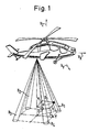
- the beam geometry for a Doppler radar system with four beams H1 to H4 can be seen, which by a corresponding antenna system on the underside of an aircraft, in this case a helicopter, be emitted.
- the indicated and respectively measured angles are only entered for the sake of completeness, but are of no interest in the present context.
- the speed components in the horizontal, lateral and vertical direction of the aircraft are indicated by V X , V Y and V Z. Since side lobes occur only within the space delimited by the main radiation lobes H1 to H4, the Doppler frequency measured unintentionally via a side lobe is faulty not only because of the changed angle of incidence, but also because of the wrong calibration for this side lobe and leads to an incorrect speed calculation.
- an integrator 2 is first required to implement the method according to the invention, at whose input the output signal b Z of a vertical accelerometer is supplied.
- the inertial vertical speed component V IZ appearing at the output of the integrator 2 acts on the one input of a comparator 5, at the other input of which the vertical speed component V DZ supplied by the Doppler radar system is supplied.
- the output-side comparison signal acts on a threshold detector 6 which emits a signal signaling a speed error as soon as a presettable limit of a permissible deviation of the two speed components determined in different ways occurs.
- the reliability and stability of the comparison result is improved by constantly monitoring and correcting the inertial vertical speed via a baro-inertial loop.
- the component V IZ of the inertial speed is integrated again in a second integrator 3 and thus acts on an input of a further comparator 7, to which the value of the barometric height H B is fed at another input.
- a return 4 arrives at the Difference signal determined correction value to an addition or subtraction circuit 1, which is also acted upon by the output signal b Z of the accelerometer.
Description
Die Erfindung betrifft ein Verfahren zur Erkennung von Fehlern bei der Geschwindigkeitsmessung mittels Doppler-Radar bei Fluggeräten, die mit einem inertialen Lagereferenzsystem und Flugregelsystem sowie mit einem barometrischen Höhenmesser ausgerüstet sind, bei welchem Verfahren durch ein Antennensystem am Fluggerät eine Mehrzahl, jedoch mindestens drei gebündelte Radarstrahlen in festgelegten Raumwinkeln gegen die Erdoberfläche gerichtet und aus der um Doppler-Frequenzen verschobenen gemessenen Energierückstreuung der einzelnen Hauptstrahlungskeulen der Mehrzahl von Radarstrahlen durch Summenbildung der skalierten Doppler-Frequenzwerte die Geschwindigkeitskomponenten in drei Raumrichtungen bestimmt werden, von denen eine die Vertikalgeschwindigkeit ist.The invention relates to a method for detecting errors in speed measurement using Doppler radar in aircraft which are equipped with an inertial position reference system and flight control system and with a barometric altimeter, in which method an antenna system on the aircraft has a plurality, but at least three, bundled radar beams The velocity components in three spatial directions, one of which is the vertical velocity, are determined from the measured energy backscatter of the individual main radiation lobes of the plurality of radar beams shifted by Doppler frequencies at fixed solid angles against the surface of the earth.
Doppler-Radargeräte werden in Starr- und Drehflüglern eingesetzt, um die Geschwindigkeit über Grund zu bestimmen.Doppler radar devices are used in fixed-wing and rotary-wing aircraft to determine the speed above ground.
Das Doppler-Radar arbeitet beispielsweise bei 13,3 GHz. Es gibt Ausführungen, bei denen die Radarenergie durch ein Antennensystem am Fluggerät mit drei oder vier hinsichtlich der Abstrahlwinkel genau festgelegten Strahlungskeulen abgestrahlt wird. Außerdem werden im vorliegenden Zusammenhang nicht weiter interessierende Modulationstechniken angewendet. Gemeinsam ist jedoch, daß die Antennen so gebaut sind, daß eventuell vorhandene Nebenzipfel in dem von den drei bzw. vier Hauptstrahlungskeulen umschlossenen Raum liegen. Dieses Prinzip funktioniert gut, solange von der unter den festgelegten Winkeln abgestrahlten Hochfrequenzenergie ein ausreichender, um die Doppler-Frequenz verschobener Anteil zurückgestreut wird.The Doppler radar, for example, operates at 13.3 GHz. There are versions in which the radar energy is emitted by an antenna system on the aircraft with three or four radiation lobes that are precisely defined with regard to the radiation angle. In addition, modulation techniques of no further interest are used in the present context. What is common, however, is that the antennas are constructed in such a way that any side lobes that may be present lie in the space enclosed by the three or four main radiation lobes. This principle works well as long as a sufficient portion shifted by the Doppler frequency is scattered back from the radio frequency energy radiated at the specified angles.
Es sind jedoch Oberflächenbedingungen bekannt, beispielsweise wenig bewegte Wasseroberflächen, Wüsten- oder "Waschbrettgelände", bei denen die Rückstreuung unter den gewünschten und geeichten Abstrahlwinkeln nicht mehr ausreicht.However, surface conditions are known, for example little-moving water surfaces, desert or "washboard terrain", in which the backscattering is no longer sufficient at the desired and calibrated radiation angles.
Da es keine von Nebenzipfelabstrahlung freie Antenne gibt und die in den Nebenzipfeln abgestrahlte Energie insbesondere bei den genannten Geländebedingungen zu einer höheren Energierückstreuung führen kann, tritt der Fall ein, daß unter den genannten Bedingungen der Radarempfänger auf die falsche Abstrahlrichtung aufgeschaltet und dementsprechend eine falsche Geschwindigkeit gemessen wird.Since there is no antenna free of sub-lobe radiation and the energy emitted in the sub-lobes can lead to higher energy backscattering, especially under the above-mentioned terrain conditions, the case arises that under the conditions mentioned the radar receiver is switched to the wrong direction of radiation and accordingly an incorrect speed is measured becomes.
Da das Problem an sich bekannt ist, wird bisher zur Erkennung dieses Zustands vorzeichenrichtig die Summe aus den Werten der drei bzw. vier gemessenen und skalierten Doppler-Frequenzen gebildet. Der Summenwert muß bei richtiger Arbeitsweise klein sein und springt auf einen großen Wert, wenn sich eine Abstrahlrichtung ändert bzw. auf eine falsche Abstrahlrichtung, also insbesondere auf einen Nebenzipfel aufgeschaltet wird. Ändern sich jedoch zwei korrespondierende Abstrahlrichtungen innerhalb der für die Summenbildung relevanten Zeit, die insbesondere vom Modulationsverfahren abhängig ist, so versagt dieses in der Fachwelt als "Beam Sum Check" bekannte Prüfverfahren.Since the problem is known per se, the sum of the values of the three or four measured and scaled Doppler frequencies has hitherto been formed with the correct sign in order to recognize this state. If the method of operation is correct, the total value must be small and jumps to a large value if a radiation direction changes or is switched to an incorrect radiation direction, that is to say in particular to a secondary lobe. However, two corresponding ones change Radiation directions within the time relevant for the sum formation, which depends in particular on the modulation method, this test fails in the technical field known as "beam sum check".
Zur Erhöhung der Entdeckungswahrscheinlichkeit des Aufschaltens des Radarempfängers auf einen unerwünschten Nebenzipfel sind auch schon "Hardware"-Maßnahmen ergriffen worden, insbesondere bei der Antennenkonstruktion im Hinblick auf eine geringe Energieabstrahlung durch Nebenzipfel. Die Nebenzipfeldämpfung ist ersichtlicherweise ein Maß für die Wahrscheinlichkeit des fehlerhaften Aufschaltens auf einen Nebenzipfel, wenn das Signal/Rausch-Verhältnis für eine der Hauptstrahlungskeulen zu klein wird."Hardware" measures have already been taken to increase the likelihood of detection of the radar receiver being switched to an undesired side lobe, in particular in the antenna construction with regard to low energy radiation from side lobes. Sub-lobe attenuation is evidently a measure of the likelihood of an erroneous intrusion on a sub-lobe if the signal-to-noise ratio becomes too small for one of the main lobes.
Die unvollständige Erkennung des Aufschaltens auf unerwünschte Nebenzipfel mit der Folge falsch gemessener Geschwindigkeiten führt bei reinen Doppler-Navigationssystemen lediglich zu einer Verschlechterung der Navigationsgenauigkeit, die zwar unbefriedigend sein mag, jedoch in der Regel korrigierbar ist und zu keinen katastrophalen Folgen führt. Werden jedoch die vom Doppler-Radarsystem gelieferten Geschwindigkeitswerte vom Flugregelsystem zur Ausführung kritischer Flugmanöver, wie z. B. dem automatischen Übergang in den Schwebeflug bei Hubschraubern benötigt, so ist eine möglichst hohe Erkennungswahrscheinlichkeit des Auftretens falscher Geschwindigkeitswerte dringend notwendig, da sonst ein Absturz des Fluggeräts droht.The incomplete detection of the switching to unwanted side lobes with the consequence of incorrectly measured speeds only leads to a deterioration in navigation accuracy in pure Doppler navigation systems, which may be unsatisfactory, but is usually correctable and does not lead to any catastrophic consequences. However, the speed values provided by the Doppler radar system are used by the flight control system to perform critical flight maneuvers, such as B. the automatic transition to hover in helicopters, the highest possible probability of the occurrence of incorrect speed values is urgently necessary, otherwise the aircraft could crash.
Der Erfindung liegt damit die Aufgabe zugrunde, ein Verfahren zur Erhöhung der Entdeckungswahrscheinlichkeit des Aufschaltens des Radarempfängers auf einen unerwünschten Nebenzipfel bei der Geschwindigkeitsmessung mittels Doppler-Radar in Fluggeräten anzugeben, die außerdem mit einem inertialen Lagereferenzsystem und Flugregelsystem sowie mit einem barometrischen Höhenmesser ausgerüstet sind.The invention is therefore based on the object of specifying a method for increasing the probability of detection of the connection of the radar receiver to an undesired secondary peak when measuring speed by means of Doppler radar in aircraft which are also equipped with an inertial position reference system and flight control system and with a barometric altimeter.
Um dem beschriebenen Mangel zu begegnen, wird gemäß der Lehre des Patentanspruchs 1 mit vorteilhafter Ergänzung und Ausgestaltung gemäß weiteren abhängigen Patentansprüchen vorgeschlagen, die aus den individuellen Doppler-Frequenzwerten berechnete Vertikalgeschwindigkeit mit der aus der sogenannten baro-inertialen Regelschleife gewonnenen inertialen Vertikalgeschwindigkeit zu vergleichen. Dieser Vergleich führt in jedem Fall zur sicheren Erkennung des Auftretens falscher Geschwindigkeitswerte aus dem Doppler-Radarsystem.In order to counter the deficiency described, it is proposed according to the teaching of
Der besondere Vorteil der Erfindung liegt darin, daß die beträchtliche Verbesserung der Fehlererkennungsmöglichkeit ohne oder nur mit sehr geringem zusätzlichem technischem Aufwand erreicht wird. Unabhängig von der Beschaffenheit der überflogenen Erdoberfläche wird durch die Erfindung mit Sicherheit immer die richtige Vertikalgeschwindigkeit ermittelt, woraus gleichzeitig auch auf die Zuverlässigkeit der über das Doppler-Radarsystem berechneten übrigen Geschwindigkeitskomponenten geschlossen werden kann.The particular advantage of the invention is that the considerable improvement in the possibility of error detection is achieved with little or no additional technical effort. Regardless of the nature of the surface over which the surface is flown, the invention always determines with certainty the correct vertical speed, from which the reliability of the other speed components calculated via the Doppler radar system can also be deduced.
Die Erfindung und vorteilhafte Einzelheiten werden nachfolgend unter Bezug auf die Zeichnung in beispielsweiser Ausführungsform näher erläutert. Es zeigen:
- Fig. 1
- ein Anschauungsbeispiel für die Strahlengeometrie bei einem Doppler-Radarsystem in einem Fluggerät und
- Fig. 2
- ein Blockschaltbild zur Erläuterung des erfindungsgemäßen Fehlererkennungsverfahrens.
- Fig. 1
- an illustrative example of the beam geometry in a Doppler radar system in an aircraft and
- Fig. 2
- a block diagram for explaining the error detection method according to the invention.
Aus der Fig. 1 ist die Strahlengeometrie für ein Doppler-Radarsystem mit vier Strahlungskeulen H₁ bis H₄ erkennbar, die von einem entsprechenden Antennensystem an der Unterseite eines Fluggeräts, in diesem Fall eines Hubschraubers, abgestrahlt werden. Die angegebenen und jeweils gemessenen Winkel sind nur der Vollständigkeit halber eingetragen, interessieren jedoch im vorliegenden Zusammenhang nicht. Die Geschwindigkeitskomponenten in horizontaler, lateraler und vertikaler Richtung des Fluggeräts sind mit VX, VY und VZ angedeutet. Da nur innerhalb des von den Hauptstrahlungskeulen H₁ bis H₄ umgrenzten Raums Nebenkeulen auftreten, ist die unbeabsichtigt über eine Nebenkeule gemessene Doppler-Frequenz nicht nur wegen des veränderten Einfallwinkels, sondern auch wegen der für diese Nebenkeule falschen Kalibration fehlerhaft und führt zu einer falschen Geschwindigkeitsberechnung.From Fig. 1, the beam geometry for a Doppler radar system with four beams H₁ to H₄ can be seen, which by a corresponding antenna system on the underside of an aircraft, in this case a helicopter, be emitted. The indicated and respectively measured angles are only entered for the sake of completeness, but are of no interest in the present context. The speed components in the horizontal, lateral and vertical direction of the aircraft are indicated by V X , V Y and V Z. Since side lobes occur only within the space delimited by the main radiation lobes H₁ to H₄, the Doppler frequency measured unintentionally via a side lobe is faulty not only because of the changed angle of incidence, but also because of the wrong calibration for this side lobe and leads to an incorrect speed calculation.
Wie aus dem Blockschaltbild der Fig. 2 ersichtlich ist, wird zur Verwirklichung des erfindungsgemäßen Verfahrens zunächst ein Integrator 2 benötigt, an dessen Eingang das Ausgangssignal bZ eines Vertikalbeschleunigungsmessers zugeführt wird. Die am Ausgang des Integrators 2 erscheinende inertiale Vertikalgeschwindigkeitskomponente VIZ beaufschlagt den einen Eingang eines Vergleichers 5, an dessen anderem Eingang die vom Doppler-Radarsystem gelieferte vertikale Geschwindigkeitskomponente VDZ zugeführt wird. Das ausgangsseitige Vergleichssignal beaufschlagt einen Schwellendetektor 6, der ein einen Geschwindigkeitsfehler signalisierendes Signal abgibt, sobald eine voreinstellbare Grenze einer zulässigen Abweichung der beiden auf unterschiedlichen Wegen ermittelten Geschwindigkeitskomponenten auftritt. Die Zuverlässigkeit und Stabilität des Vergleichsergebnisses wird dadurch verbessert, daß die inertiale Vertikalgeschwindigkeit über eine baro-inertiale Schleife ständig überwacht und korrigiert wird. Zu diesem Zweck wird die Komponente VIZ der inertialen Geschwindigkeit in einem zweiten Integrator 3 nochmals integriert und beaufschlagt damit einen Eingang eines weiteren Vergleichers 7, dem an einem anderen Eingang der Wert der barometrischen Höhe HB zugeführt wird. Über eine Rückführung 4 gelangt ein aus dem Differenzsignal ermittelter Korrekturwert auf eine Additions- bzw. Subtraktionsschaltung 1, die außerdem durch das Ausgangssignal bZ des Beschleunigungsmessers beaufschlagt ist.As can be seen from the block diagram of FIG. 2, an integrator 2 is first required to implement the method according to the invention, at whose input the output signal b Z of a vertical accelerometer is supplied. The inertial vertical speed component V IZ appearing at the output of the integrator 2 acts on the one input of a comparator 5, at the other input of which the vertical speed component V DZ supplied by the Doppler radar system is supplied. The output-side comparison signal acts on a threshold detector 6 which emits a signal signaling a speed error as soon as a presettable limit of a permissible deviation of the two speed components determined in different ways occurs. The reliability and stability of the comparison result is improved by constantly monitoring and correcting the inertial vertical speed via a baro-inertial loop. For this purpose, the component V IZ of the inertial speed is integrated again in a second integrator 3 and thus acts on an input of a further comparator 7, to which the value of the barometric height H B is fed at another input. A return 4 arrives at the Difference signal determined correction value to an addition or
Ergibt der Vergleich der beiden aus unterschiedlichen Quellen bestimmten Vertikalgeschwindigkeiten VIZ bzw. VDZ, daß die vom Doppler-Radarsystem gelieferten Werte der Vertikalgeschwindigkeit unbrauchbar sind, so müssen diese substituiert werden. Selbstverständlich sind in diesem Fall auch die longitudinale und die laterale Komponente falsch. Die Substitution der vertikalen Geschwindigkeitskomponente erfolgt dann durch die inertiale Vertikalgeschwindigkeitskomponente und die horizontalen Komponenten lassen sich beispielsweise für den kurzen erforderlichen Zeitraum aus dem letzten berechneten Wind und den Fahrtkomponenten bestimmen.If the comparison of the two vertical speeds V IZ or V DZ determined from different sources shows that the values of the vertical speed supplied by the Doppler radar system are unusable, these must be substituted. Of course, the longitudinal and lateral components are also incorrect in this case. The vertical speed component is then substituted by the inertial vertical speed component and the horizontal components can be determined, for example, for the short required period from the last calculated wind and the travel components.
Claims (3)
- Method for detecting errors in the velocity measurement of aircraft by means of Doppler radar which are equipped with an inertial position reference and flight control system and with a barometric altimeter, in which method a plurality, but at least three focused radar beams are directed at predetermined solid angles towards the earth's surface by means of an antenna system on the aircraft and from the measured energy backscatter, displaced by Doppler frequencies, of the individual main radiation lobes (H₁ to H₄) of the plurality of radar beams the velocity components (VX, VY, YZ), one of which is the vertical velocity, are determined in the three spatial directions by forming the sum of the scaled Doppler frequency values, characterised in that, in order to increase the probability of discovery of the radar receiving system being locked to backscattered energy from side lobes of the focused radar beams, the inertial vertical velocity component (VIZ) obtained via a baroinertial control loop is compared with the vertical velocity component (VDZ) determined from the Doppler frequencies and from the comparison an error detection signal is derived.
- Method according to Claim 1, characterised in that, in order to obtain the inertial vertical velocity component (VIZ), the signal (bZ) of a vertical accelerometer is integrated and the integrated signal (VZ) is supplied to one input of a comparator (5) to the other input of which the vertical velocity component (VDZ) of the Doppler radar velocity meter is applied and in that an output value of the comparator (5) exceeding a predeterminable threshold value is evaluated as an error.
- Method according to Claim 2, characterised in that the inertial vertical acceleration component (VIZ) is integrated twice and this twice-integrated value is compared with the barometric altitude value (HB), and in that the altitude difference value determined from the comparison is fed back as converted correction value (k) to the output of the vertical accelerometer.
Priority Applications (4)
| Application Number | Priority Date | Filing Date | Title |
|---|---|---|---|
| DE8787116977T DE3786803D1 (en) | 1987-11-17 | 1987-11-17 | METHOD FOR INCREASING ERROR DETECTION IN THE SPEED MEASUREMENT OF AIRCRAFT DEVICES USING DOPPLER RADAR. |
| EP87116977A EP0316471B1 (en) | 1987-11-17 | 1987-11-17 | Method for increasing error detection at the speed measurement of aircraft by means of a doppler radar |
| CA000581727A CA1323413C (en) | 1987-11-17 | 1988-10-31 | Method for increasing error detection in the measurement of the velocity of aircraft by means of doppler radar |
| US07/267,016 US5109230A (en) | 1987-11-17 | 1988-11-04 | Method for aircraft velocity error detection with a Doppler radar |
Applications Claiming Priority (1)
| Application Number | Priority Date | Filing Date | Title |
|---|---|---|---|
| EP87116977A EP0316471B1 (en) | 1987-11-17 | 1987-11-17 | Method for increasing error detection at the speed measurement of aircraft by means of a doppler radar |
Publications (2)
| Publication Number | Publication Date |
|---|---|
| EP0316471A1 EP0316471A1 (en) | 1989-05-24 |
| EP0316471B1 true EP0316471B1 (en) | 1993-07-28 |
Family
ID=8197455
Family Applications (1)
| Application Number | Title | Priority Date | Filing Date |
|---|---|---|---|
| EP87116977A Expired - Lifetime EP0316471B1 (en) | 1987-11-17 | 1987-11-17 | Method for increasing error detection at the speed measurement of aircraft by means of a doppler radar |
Country Status (4)
| Country | Link |
|---|---|
| US (1) | US5109230A (en) |
| EP (1) | EP0316471B1 (en) |
| CA (1) | CA1323413C (en) |
| DE (1) | DE3786803D1 (en) |
Families Citing this family (9)
| Publication number | Priority date | Publication date | Assignee | Title |
|---|---|---|---|---|
| US6507289B1 (en) | 1999-10-05 | 2003-01-14 | Honeywell International Inc. | Apparatus and method of checking radio altitude reasonableness |
| AU2003272190A1 (en) * | 2002-04-17 | 2004-01-19 | Aerovironment, Inc. | High altitude platform deployment system |
| US6980153B2 (en) * | 2004-05-17 | 2005-12-27 | Honeywell International Inc. | Radar altimeter for helicopter load carrying operations |
| US7248208B2 (en) * | 2004-06-10 | 2007-07-24 | Honeywell International Inc. | Methods and systems for maintaining a position during hovering operations |
| US7970501B2 (en) * | 2005-03-08 | 2011-06-28 | Honeywell International Inc. | Methods and systems utilizing true airspeed to improve vertical velocity accuracy |
| JP2006337025A (en) * | 2005-05-31 | 2006-12-14 | Hitachi Ltd | Absolute velocity measuring device |
| CN102384755B (en) * | 2010-09-02 | 2016-01-06 | 何平 | High-accuracy method for measuring instant navigational speed of airborne phased array whether radar |
| US8952841B1 (en) * | 2012-01-13 | 2015-02-10 | Rockwell Collins, Inc. | System and method for TCAS based navigation |
| FR3036497B1 (en) * | 2015-05-19 | 2017-06-16 | Airbus Operations Sas | METHOD AND SYSTEM FOR DATA MANAGEMENT OF AN AIRCRAFT RADIOALTIMETER |
Family Cites Families (24)
| Publication number | Priority date | Publication date | Assignee | Title |
|---|---|---|---|---|
| US3088109A (en) * | 1956-10-10 | 1963-04-30 | Lab For Electronics Inc | Signal processing apparatus |
| US3140483A (en) * | 1959-04-03 | 1964-07-07 | Stephen J Sikora | Barometric-radar altitude control system |
| NL256566A (en) * | 1959-10-07 | |||
| NL257066A (en) * | 1959-10-20 | |||
| US3242736A (en) * | 1963-10-01 | 1966-03-29 | Bell Aerospace Corp | Altimeter system |
| US4175285A (en) * | 1967-08-25 | 1979-11-20 | Thomson-Csf | Navigational system of high-speed aircraft |
| US3430236A (en) * | 1967-09-15 | 1969-02-25 | Gen Precision Systems Inc | Method and means for eliminating beam reflection errors in a doppler radar system |
| DE1940620A1 (en) * | 1969-08-09 | 1971-02-11 | Teldix Gmbh | Navigation system for aircraft, especially for aircraft taking off and landing vertically |
| US3715718A (en) * | 1970-08-11 | 1973-02-06 | Sundstrand Data Control | Ground proximity warning system utilizing radio and barometric altimeter combination |
| FR2137306B1 (en) * | 1971-05-18 | 1973-05-11 | Dassault Electronique | |
| US3710386A (en) * | 1971-07-06 | 1973-01-09 | Singer Co | Time-shared frequency tracking loop |
| US3921170A (en) * | 1972-07-31 | 1975-11-18 | Us Air Force | Method and system for computing altitude over a target and the horizontal range thereof |
| US3996589A (en) * | 1972-12-22 | 1976-12-07 | Rca Corporation | Monopulse radar system |
| US3890614A (en) * | 1973-02-20 | 1975-06-17 | Intercontinental Dynamics Corp | Integrated radar-pneumatic altimeter display device |
| US4070674A (en) * | 1973-10-17 | 1978-01-24 | The Singer Company | Doppler heading attitude reference system |
| US3860925A (en) * | 1974-01-09 | 1975-01-14 | Singer Co | Velocity-altimeter frequency-modulation continuous-wave doppler system |
| US3936797A (en) * | 1974-05-28 | 1976-02-03 | Intercontinental Dynamics Corporation | Radar-barometric altitude indicator |
| US3934222A (en) * | 1975-04-02 | 1976-01-20 | Sundstrand Data Control, Inc. | Terrain closure warning system with climb inhibit and altitude gain measurement |
| US4431994A (en) * | 1981-05-06 | 1984-02-14 | The United States Of America As Represented By The Secretary Of The Air Force | Combined radar/barometric altimeter |
| US4567483A (en) * | 1982-12-10 | 1986-01-28 | Sundstrand Data Control, Inc. | Position based ground proximity warning system for aircraft |
| US4594676A (en) * | 1982-12-27 | 1986-06-10 | Rockwell International Corporation | Aircraft groundspeed measurement system and technique |
| US4584646A (en) * | 1983-06-29 | 1986-04-22 | Harris Corporation | System for correlation and recognition of terrain elevation |
| US4646244A (en) * | 1984-02-02 | 1987-02-24 | Sundstrand Data Control, Inc. | Terrain advisory system |
| DE3677018D1 (en) * | 1986-11-12 | 1991-02-21 | Litef Gmbh | METHOD FOR DETERMINING THE FLIGHT ALTITUDE OF AN AIRCRAFT. |
-
1987
- 1987-11-17 DE DE8787116977T patent/DE3786803D1/en not_active Expired - Fee Related
- 1987-11-17 EP EP87116977A patent/EP0316471B1/en not_active Expired - Lifetime
-
1988
- 1988-10-31 CA CA000581727A patent/CA1323413C/en not_active Expired - Fee Related
- 1988-11-04 US US07/267,016 patent/US5109230A/en not_active Expired - Fee Related
Also Published As
| Publication number | Publication date |
|---|---|
| EP0316471A1 (en) | 1989-05-24 |
| DE3786803D1 (en) | 1993-09-02 |
| US5109230A (en) | 1992-04-28 |
| CA1323413C (en) | 1993-10-19 |
Similar Documents
| Publication | Publication Date | Title |
|---|---|---|
| DE69922391T2 (en) | ALTIMETER RADAR WITH INTERFEROMETRIC SYNTHETIC APERTURE | |
| DE10143561B4 (en) | Method and system for locating emitters | |
| EP0359911B1 (en) | Radar altimeter | |
| DE60016748T2 (en) | METHOD AND DEVICE FOR DETERMINING THE VERTICAL SPEED OF A PLANE | |
| EP0316471B1 (en) | Method for increasing error detection at the speed measurement of aircraft by means of a doppler radar | |
| DE60319370T2 (en) | METHOD AND DEVICE FOR EXACT PHASE DETECTION | |
| DE102018200757A1 (en) | Method and apparatus for detecting critical lateral movements | |
| DE102020102902A1 (en) | Vehicle radar device and control method therefor | |
| DE602004002594T2 (en) | RADAR HEIGHT GAUGE WITH ADDITIONAL FORWARD DISTANCE MEASUREMENT | |
| DE2830835A1 (en) | DEVICE FOR MONITORING ERROR-FREE | |
| DE3835992A1 (en) | COLLISION PREVENTION SYSTEM | |
| EP0006448B1 (en) | Method for determining the location of surface-bound vehicles in an urban area | |
| EP2078965B1 (en) | Monitoring device for an augmented satellite-based positioning system and augmented satellite-based positioning system | |
| EP2150172B1 (en) | Device and method for correcting a measured blood pressure | |
| DE2554301A1 (en) | PROCEDURE FOR DETERMINING THE POSITION OF AN AIRPLANE AND WIRING ARRANGEMENT FOR PERFORMING THIS PROCEDURE | |
| DE3823814C2 (en) | ||
| EP0199107B1 (en) | Process and device for the suppression of rain echos in a terrain-following radar | |
| EP1736733B1 (en) | Method for determining a navigation solution of a navigation system having a terrain-navigation module and a navigation system | |
| WO2019233744A1 (en) | Secure method for determining the position of a receiving device | |
| DE102018200755A1 (en) | Method and device for plausibility of a transverse movement | |
| DE3337135A1 (en) | Collision-prevention system for vehicles | |
| WO1999004281A1 (en) | Satellite navigation | |
| EP0378751A2 (en) | Laser altimeter | |
| DE2648101A1 (en) | GROUND STATION FOR A TWO-WAY DISTANCE MEASURING SYSTEM | |
| DE3642767B3 (en) | Angle tracking radar system |
Legal Events
| Date | Code | Title | Description |
|---|---|---|---|
| PUAI | Public reference made under article 153(3) epc to a published international application that has entered the european phase |
Free format text: ORIGINAL CODE: 0009012 |
|
| AK | Designated contracting states |
Kind code of ref document: A1 Designated state(s): DE ES FR GB IT NL |
|
| 17P | Request for examination filed |
Effective date: 19891012 |
|
| 17Q | First examination report despatched |
Effective date: 19920310 |
|
| GRAA | (expected) grant |
Free format text: ORIGINAL CODE: 0009210 |
|
| AK | Designated contracting states |
Kind code of ref document: B1 Designated state(s): DE ES FR GB IT NL |
|
| PG25 | Lapsed in a contracting state [announced via postgrant information from national office to epo] |
Ref country code: NL Effective date: 19930728 |
|
| GBT | Gb: translation of ep patent filed (gb section 77(6)(a)/1977) |
Effective date: 19930727 |
|
| REF | Corresponds to: |
Ref document number: 3786803 Country of ref document: DE Date of ref document: 19930902 |
|
| ITF | It: translation for a ep patent filed |
Owner name: STUDIO TORTA SOCIETA' SEMPLICE |
|
| PG25 | Lapsed in a contracting state [announced via postgrant information from national office to epo] |
Ref country code: ES Free format text: LAPSE BECAUSE OF FAILURE TO SUBMIT A TRANSLATION OF THE DESCRIPTION OR TO PAY THE FEE WITHIN THE PRESCRIBED TIME-LIMIT Effective date: 19931108 |
|
| ET | Fr: translation filed | ||
| NLV1 | Nl: lapsed or annulled due to failure to fulfill the requirements of art. 29p and 29m of the patents act | ||
| PLBE | No opposition filed within time limit |
Free format text: ORIGINAL CODE: 0009261 |
|
| STAA | Information on the status of an ep patent application or granted ep patent |
Free format text: STATUS: NO OPPOSITION FILED WITHIN TIME LIMIT |
|
| 26N | No opposition filed | ||
| PGFP | Annual fee paid to national office [announced via postgrant information from national office to epo] |
Ref country code: FR Payment date: 19951120 Year of fee payment: 9 |
|
| PGFP | Annual fee paid to national office [announced via postgrant information from national office to epo] |
Ref country code: GB Payment date: 19951121 Year of fee payment: 9 |
|
| PGFP | Annual fee paid to national office [announced via postgrant information from national office to epo] |
Ref country code: DE Payment date: 19951128 Year of fee payment: 9 |
|
| PG25 | Lapsed in a contracting state [announced via postgrant information from national office to epo] |
Ref country code: GB Effective date: 19961117 |
|
| GBPC | Gb: european patent ceased through non-payment of renewal fee |
Effective date: 19961117 |
|
| PG25 | Lapsed in a contracting state [announced via postgrant information from national office to epo] |
Ref country code: FR Effective date: 19970731 |
|
| PG25 | Lapsed in a contracting state [announced via postgrant information from national office to epo] |
Ref country code: DE Effective date: 19970801 |
|
| REG | Reference to a national code |
Ref country code: FR Ref legal event code: ST |
|
| PG25 | Lapsed in a contracting state [announced via postgrant information from national office to epo] |
Ref country code: IT Free format text: LAPSE BECAUSE OF NON-PAYMENT OF DUE FEES;WARNING: LAPSES OF ITALIAN PATENTS WITH EFFECTIVE DATE BEFORE 2007 MAY HAVE OCCURRED AT ANY TIME BEFORE 2007. THE CORRECT EFFECTIVE DATE MAY BE DIFFERENT FROM THE ONE RECORDED. Effective date: 20051117 |