EP0315742A2 - Helmet mounted display system - Google Patents
Helmet mounted display system Download PDFInfo
- Publication number
- EP0315742A2 EP0315742A2 EP88113653A EP88113653A EP0315742A2 EP 0315742 A2 EP0315742 A2 EP 0315742A2 EP 88113653 A EP88113653 A EP 88113653A EP 88113653 A EP88113653 A EP 88113653A EP 0315742 A2 EP0315742 A2 EP 0315742A2
- Authority
- EP
- European Patent Office
- Prior art keywords
- helmet
- map
- symbols
- display device
- viewer
- Prior art date
- Legal status (The legal status is an assumption and is not a legal conclusion. Google has not performed a legal analysis and makes no representation as to the accuracy of the status listed.)
- Ceased
Links
Images


Classifications
-
- G—PHYSICS
- G02—OPTICS
- G02B—OPTICAL ELEMENTS, SYSTEMS OR APPARATUS
- G02B27/00—Optical systems or apparatus not provided for by any of the groups G02B1/00 - G02B26/00, G02B30/00
- G02B27/01—Head-up displays
- G02B27/017—Head mounted
-
- G—PHYSICS
- G02—OPTICS
- G02B—OPTICAL ELEMENTS, SYSTEMS OR APPARATUS
- G02B27/00—Optical systems or apparatus not provided for by any of the groups G02B1/00 - G02B26/00, G02B30/00
- G02B27/01—Head-up displays
- G02B27/0101—Head-up displays characterised by optical features
- G02B2027/014—Head-up displays characterised by optical features comprising information/image processing systems
-
- G—PHYSICS
- G02—OPTICS
- G02B—OPTICAL ELEMENTS, SYSTEMS OR APPARATUS
- G02B27/00—Optical systems or apparatus not provided for by any of the groups G02B1/00 - G02B26/00, G02B30/00
- G02B27/01—Head-up displays
- G02B27/0179—Display position adjusting means not related to the information to be displayed
- G02B2027/0187—Display position adjusting means not related to the information to be displayed slaved to motion of at least a part of the body of the user, e.g. head, eye
-
- G—PHYSICS
- G02—OPTICS
- G02B—OPTICAL ELEMENTS, SYSTEMS OR APPARATUS
- G02B27/00—Optical systems or apparatus not provided for by any of the groups G02B1/00 - G02B26/00, G02B30/00
- G02B27/01—Head-up displays
- G02B2027/0192—Supplementary details
- G02B2027/0198—System for aligning or maintaining alignment of an image in a predetermined direction
Definitions
- the invention relates to a position display device for superimposing characters, lines and symbols according to the preamble of claim 1.
- LDG position display devices
- a helmet-mounted visor device has become known relative to a predetermined reference field or image.
- the visor symbol is generated on a cathode ray tube mounted on the helmet and faded into the eye via a semi-transparent mirror in reference to the background.
- This reference system is gyro-stabilized and is located on the helmet.
- the present invention has for its object to provide a location display device that allows a combination of conventional map display with the overlay of additional information in the form of characters and symbols, this overlay is still individually controllable for each individual viewer, in the sense that different Observers are given their own information that is specific to them. This means that different surgeons can project different information onto the card at the same time and everyone only sees his or her image, while a main surgeon can see all information at will.
- Figure 1 illustrates the structure and composition of such an overall arrangement in one embodiment, which is described below in the essential details.
- a map 12 in the size of 1m x 1m is attached to a wall, a plate or a frame.
- a marking light source 13 is arranged as fixed points for the geometric location and orientation determination of the viewer (s).
- a computer 14 with an operating device is now assigned to this arrangement.
- the viewer or surgeons are equipped with a helmet or headband 10 on which a viewing device 11 is mounted.
- This device allows the viewer to have a clear view of the map on one hand and, on the other hand, to overlay pictorial representations on the map within certain limits of their position and the orientation of their viewing direction.
- These on-screen displays are largely correct in size and free of distortion at the desired or specified location on the map. This will be discussed in more detail below.
- the viewing device is designed in such a way that the viewer is unduly stressed neither by the weight of the device nor by its moment of inertia.
- the exemplary embodiment of a position display device described here is thus composed of two main components, namely the stationary, space-bound device and the device carried by the respective viewer.
- the interfaces between the stationary and the moving parts can be freely defined within certain limits depending on the existing parameters.
- the stationary device mainly includes the position and direction system (computer desk with operator 14).
- the latter is composed of the above-mentioned map 12 and a plurality of — preferably four — light sources 13 arranged orthogonally to one another on the map wall, for example at the map corners, which can be luminescent diodes.
- three would not be in one Line-arranged light sources are sufficient as reference points, but the computational effort when using four light sources is considerably less, which is only advantageous for the required real-time calculation.
- the small viewing device 11 which uses a position-sensitive diode 17 with a surface configuration behind an objective 18 as illustrated in FIGS. 2 and 3 as a sensor for the alignment.
- the lens has a focal length that corresponds to the given conditions.
- Objective 18 and position sensitive diode (PSD) 17 are assigned to a camera.
- the electrodes attached to the edges of the position diode 17, 17a act like a current divider and reflect the position of the light spot 22 in two orthogonal directions as analog electrical values.
- the angular position of the sensor attached to the helmet 10 with respect to all the marking light sources 13 can be determined simultaneously or in succession in a sufficiently rapid sequence. From these values, the projection direction for the reflected signals and the distance to the map 12 are calculated in real time in the computer 14.
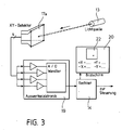
- FIG. 3 schematically shows the arrangement and circuitry of a position-sensitive diode in surface design 17a with downstream amplifiers and analog-digital converters in evaluation electronics 19.
- the symbols 22 are superimposed on the field of view of the viewer through the screen 20 of a small cathode ray tube or other display mounted on the helmet 10 with the interposition of a 45 ° inclined semi-reflecting mirror 21 and a converging lens switched into the beam path as a magnifying glass 18a virtual image of the monitor screen 20 appearing on the map plane 12a.
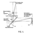
- FIG. 4 outlines the beam path of the optical image described above, a small magnification scale being chosen for a better overview.
- the position of the symbols 22 on the monitor screen 20 is controlled by the computer of the symbol remote control 15 so that the location of the virtual images on the map plane 12a can always be seen at the desired location regardless of the viewer's head movement and his position in space.
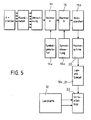
- FIG. 5 shows a block diagram of the overall arrangement, from which the entire mode of operation of the technical equipment can be seen, so that further explanations may not be necessary.
- To measure the position of the viewer it is also possible to continuously determine its distance from the reference points 13 on the map plane 12a by means of a range finder. This can be arranged both on the helmet 10 and on the map plane - preferably at one of the reference points 13. However, means for determining the orientation of the helmet 10 in all three axes must be provided in this special case.
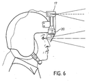
- FIG. 6 shows a schematic image of an operator or viewer who works with the position display device LDG.
- the monocular viewing device which - as already mentioned - consists of the monitor screen 20, a magnifying glass and an inclined semi-reflecting mirror for viewing the image as well as a camera-like multiple angle sensor with lens and position diode 17.
- the illuminable area of the monitor 20 should be so large that the virtual image 22 produced takes up an edge length of one and a half to two times the map dimensions at the next viewing distance.
- the position of the symbols 22 and other representations is controlled by the computer 15 so that they are at the desired or required location on the map 12 for the viewer. It is therefore not a question of a projection of the symbols 22 onto the map, which is visible to everyone present, but rather an individual visualization of the symbols for the individual viewer, it being possible for different viewers to be given different representations.
Abstract
Description
Die Erfindung bezieht sich auf ein Lagedarstellungsgerät zur Überlagerung von Zeichen, Linien und Symbolen gemäß dem Gattungsbegriff des Anspruchs 1.The invention relates to a position display device for superimposing characters, lines and symbols according to the preamble of claim 1.
Solche Lagedarstellungsgeräte - kurz LDG genannt - sind in verschiedenen Ausführungsformen bekannt. Alle diese Geräte sind jedoch mit zum Teil sogar sehr großen Problemen behaftet, so beispielsweise durch die hohe Informationsdichte einer taktischen Karte, die bisher eine kartografische Darstellung mit hoher Detailauflösung nicht ermöglichen.Such position display devices - called LDG for short - are known in various embodiments. However, all of these devices are sometimes associated with very large problems, for example due to the high information density of a tactical map, which have not hitherto made possible a cartographic display with high detail resolution.
Durch die DE-OS 34 26 505 ist eine helmmontierte Visiereinrichtung relativ zu einem vorgegebenen Bezugsfeld bzw. -bild bekanntgeworden. Hier wird das Visiersymbol auf einer am Helm montierten Kathodenstrahlröhre erzeugt und über einen halbdurchlässigen Spiegel in Referenz zum Hintergrund ins Auge eingeblendet. Dieses Referenzsystem ist kreiselstabilisiert und befindet sich am Helm.From DE-OS 34 26 505, a helmet-mounted visor device has become known relative to a predetermined reference field or image. Here the visor symbol is generated on a cathode ray tube mounted on the helmet and faded into the eye via a semi-transparent mirror in reference to the background. This reference system is gyro-stabilized and is located on the helmet.
Aber auch hier ist eine Beschränkung auf zu kleine Bildausschnitte gegeben, nämlich nur maximal auf 40 x 40 cm, während ein Bildausschnitt von mindestens 100 x 100 cm gefordert ist. Aber auch das Gerätevolumen und das relativ hohe Gewicht sind als Nachteile der bisher vorgeschlagenen Ausführungsformen anzuführen.But here, too, there is a limitation to image sections that are too small, namely only a maximum of 40 x 40 cm, while an image section of at least 100 x 100 cm is required. However, the device volume and the relatively high weight can also be mentioned as disadvantages of the previously proposed embodiments.
Der vorliegenden Erfindung liegt die Aufgabe zugrunde, ein Lagedarstellungsgerät zu schaffen, das eine Kombination von konventioneller Kartendarstellung mit der Überlagerung zusätzlicher Informationen in Form von Zeichen und Symbolen erlaubt, wobei diese Überlagerung noch für jeden einzelnen Betrachter individuell steuerbar ist, in dem Sinne, daß verschiedene Beobachter eigene individuell für sie bestimmte Informationen dargeboten bekommen. Das heißt, verschiedene Operateure können verschiedene Informationen gleichzeitig auf die Karte projizieren und jeder sieht nur sein Bild, während ein Hauptoperateur beliebig alle Informationen sehen kann.The present invention has for its object to provide a location display device that allows a combination of conventional map display with the overlay of additional information in the form of characters and symbols, this overlay is still individually controllable for each individual viewer, in the sense that different Observers are given their own information that is specific to them. This means that different surgeons can project different information onto the card at the same time and everyone only sees his or her image, while a main surgeon can see all information at will.
Diese Aufgabe wird durch die im Anspruch 1 aufgeführten Maßnahmen gelöst. In den Unteransprüchen sind Ausgestaltungen und Weiterbildungen angegeben, in der nachfolgenden Beschreibung ist ein Ausführungsbeispiel erläutert und in den Figuren der Zeichnung skizziert. Es zeigen:
- Fig. 1 ein Schemabild einer Lagedarstellung mit Symboleinblendung und Symbolsteuerung,
- Fig. 2 ein Schemabild einer Lagedarstellung mit Bestimmung von Position und Blickrichtung,
- Fig. 3 ein Blockschaltbild der Anordnung zur Bestimmung von Betrachterposition und Orientierung,
- Fig. 4 ein Schemabild bezüglich des Strahlenganges der optischen Abbildung zur Lagedarstellung,
- Fig. 5 ein Blockschaltbild der Gesamtanordnung eines Lagedarstellungsgerätes,
- Fig. 6 ein Schemabild eines Operateurs mit der auf einem Helm montierten monokularen Sichteinrichtung.
- 1 is a schematic image of a situation with symbol display and symbol control,
- 2 shows a schematic diagram of a positional representation with determination of position and viewing direction,
- 3 shows a block diagram of the arrangement for determining the observer position and orientation,
- 4 shows a schematic image with respect to the beam path of the optical image for the positional representation,
- 5 shows a block diagram of the overall arrangement of a position display device,
- Fig. 6 is a schematic image of an operator with the monocular vision device mounted on a helmet.
Die Kombination einer fein aufgelösten kartografischen Darstellung mit einer beliebig steuerbaren Überlagerung veränderbarer Informationssymbole für den einzelnen Betrachter läßt sich bei vergleichsweise einfachem technischen Aufwand dadurch erreichen, daß eine normale Wandkarte in der Größe von 1m x 1m und im Maßstab von 1 : 50 000 bis 1 : 500 000 benützt wird und der oder die Betrachter eine kleine Apparatur erhalten, durch welche für sie sichtbare, elektronisch erzeugte Symbole generiert werden. Diese Symbole werden derart in das Gesichtsfeld eingebracht, daß sie für das Auge des Beobachters unter allen auftretenden Betrachtungssituationen als virtuelle Bilder an der jeweils ausgewählten Stelle der Karte erscheinen.The combination of a finely resolved cartographic representation with an arbitrarily controllable overlay of changeable information symbols for the individual viewer can be achieved with comparatively simple technical effort by the fact that a normal wall map in the size of 1m x 1m and on a scale of 1: 50,000 to 1: 500,000 is used and the viewer (s) receive a small piece of equipment that generates electronically generated symbols that are visible to them. These symbols are introduced into the field of view in such a way that they appear to the observer's eye as virtual images at the respectively selected location on the map under all observation situations that occur.
Die Figur 1 verdeutlicht den Aufbau und die Zusammensetzung so einer Gesamtanordnung in einem Ausführungsbeispiel, das nachfolgend in den wesentlichen Einzelheiten beschrieben wird. An einer Wand, einer Platte oder einem Rahmen ist eine Landkarte 12 in der Größe von 1m x 1m befestigt. An den vier Ecken der Kartenfläche sind je eine Markierungslichtquelle 13 als Fixpunkte zur geometrischen Ortsbestimmung und Orientierungsbestimmung des oder der Betrachter angeordnet. Dieser Anordnung ist nun ein Rechner 14 mit Bedienungseinrichtung zugeordnet.Figure 1 illustrates the structure and composition of such an overall arrangement in one embodiment, which is described below in the essential details. A
Der oder die Betrachter bzw. Operateure sind mit einem Helm oder Stirnband 10 ausgerüstet an dem ein Betrachtungsgerät 11 montiert ist. Dieses Gerät erlaubt dem Betrachter einmal den freien Blick auf die Karte und zum andernmal ein in gewissen Grenzen von seiner Position und der Orientierung seiner Blickrichtung unabhängiges Überlagern bildlicher Darstellungen auf der Karte. Diese eingeblendeten Darstellungen sind weitgehend größenrichtig und verzerrungsfrei am gewünschten oder vorgegebenen Ort der Karte. Nachfolgend wird hierzu noch näher eingegangen. Zu erwähnen wäre hier noch, daß das Betrachtungsgerät so ausgeführt ist, daß der Betrachter weder durch das Gewicht des Gerätes noch durch dessen Trägheitsmoment über Gebühr beansprucht wird.The viewer or surgeons are equipped with a helmet or
Das hier beschriebene Ausführungsbeispiel eines Lagedarstellungsgerätes setzt sich also aus zwei Hauptkomponenten zusammen, nämlich der ortsfesten, raumgebundenen Einrichtung und dem vom jeweiligen Betrachter getragenen Gerät. Hierbei lassen sich die Nahtstellen zwischen den ortsfesten und den beweglichen Teilen in Abhängigkeit von den vorhandenen Parametern in gewissen Grenzen frei definieren. Zu der ortsfesten Einrichtung gehören neben den Elementen zur Steuerung der eingeblendeten Informationen ( Pult für die Symbolfernsteuerung 15 ) hauptsächlich das Lage- und Richtungssystem ( Rechnerpult mit Bedienung 14 ). Letzteres setzt sich aus der bereits angesprochenen Landkarte 12 und aus mehreren - vorzugsweise vier - orthogonal zueinander auf der Kartenwand - beispielsweise an den Kartenecken - angeordneten Lichtquellen 13 zusammen, welche Lumineszenzdioden sein können. Für eine Ortsbestimmung würden drei nicht in einer Linie angeordnete Lichtquelle als Referenzpunkte ausreichen, jedoch ist der rechnerische Aufwand bei Verwendung von vier Lichtquellen erheblich geringer, was bei der erforderlichen Echtzeitrechnung nur vorteilhaft ist.The exemplary embodiment of a position display device described here is thus composed of two main components, namely the stationary, space-bound device and the device carried by the respective viewer. The interfaces between the stationary and the moving parts can be freely defined within certain limits depending on the existing parameters. In addition to the elements for controlling the information displayed (console for symbol remote control 15), the stationary device mainly includes the position and direction system (computer desk with operator 14). The latter is composed of the above-mentioned
An den Helmen 10 der Betrachter befindet sich das kleine Betrachtungsgerät 11, das als Sensor für die Ausrichtung eine positionsempfindliche Diode 17 in Flächenausführung hinter einem Objectiv 18 - wie in Fig. 2 und 3 veranschaulicht - verwendet. Das Objektiv weist eine den gegebenen Verhältnissen entsprechende Brennweite auf. Objektiv 18 und positionsempfindliche Diode (PSD) 17 sind einer Kamera zugeordnet. Die an den Kanten der Positionsdiode 17, 17a angebrachten Elektroden wirken wie ein Stromteiler und geben die Position des Lichtfleckes 22 in zwei orthogonalen Richtungen als analoge elektrische Werte wieder. Durch die Verwendung eines Multiplexverfahrens läßt sich so die Winkellage des am Helm 10 angebrachten Sensors in bezug auf alle Markierungs-Lichtquellen 13 simultan oder in ausreichend schneller Folge nacheinander bestimmen. Aus diesen Werten werden in dem Rechner 14 in Echtzeit die Projektionsrichtung für die eingespiegelten Signale und die Entfernung zur Karte 12 errechnet.On the
In der Figur 3 ist die Anordnung und Schaltung einer positionsempfindlichen Diode in Flächenausführung 17a mit nachgeschalteten Verstärkern und Analog-Digital-Wandlern in einer Auswertelektronik 19 schematisch dargestellt. Das Überlagern der Symbole 22 in das Gesichtsfeld des Betrachters geschieht durch den Bildschirm 20 einer kleinen am Helm 10 montierten Kathodenstrahlröhre oder eines anderen Displays unter Zwischenschaltung eines um 45° geneigten halbreflektierenden Spiegels 21 und einer als Lupe 18a in den Strahlengang geschalteten Sammellinse, die ein auf der Kartenebene 12a erscheinendes virtuelles Bild des Monitor-Schirmes 20 erzeugt.FIG. 3 schematically shows the arrangement and circuitry of a position-sensitive diode in
Die Figur 4 skizziert den Strahlengang der vorbeschriebenen optischen Abbildung, wobei zur besseren Übersicht ein geringer Vergrößerungsmaßstab gewählt wurde. Die Lage der Symbole 22 auf dem Monitorschirm 20 wird durch den Rechner der Symbolfernsteuerung 15 so gesteuert, daß der Ort der virtuellen Bilder auf der Kartenebene 12a unabhängig von der Kopfbewegung des Betrachters und von dessen Lage im Raum immer an der gewünschten Stelle zu sehen ist.FIG. 4 outlines the beam path of the optical image described above, a small magnification scale being chosen for a better overview. The position of the
In der Figur 5 ist ein Blockdiagramm der Gestamtanordnung dargestellt, aus dem sich die gesamte Wirkungsweise der technischen Gerätschaft erkennen läßt, so daß sich weitere Ausführungen erübrigen dürften. Zur Vermessung der Stellung der bzw. des Betrachters ist es weiterhin möglich, dessen Entfernung von den Referenzpunkten 13 auf der Kartenebene 12a laufend mittels eines Entfernungsmessers zu bestimmen. Dieser kann sowohl auf dem Helm 10 als auch an der Kartenebene - vorzugsweise an einem der Referenzpunkte 13 - angeordnet sein. Dabei müssen jedoch auf in diesem speziellen Fall Mittel zur Bestimmung der Orientierung des Helmes 10 in allen drei Achsen vorgesehen werden.FIG. 5 shows a block diagram of the overall arrangement, from which the entire mode of operation of the technical equipment can be seen, so that further explanations may not be necessary. To measure the position of the viewer, it is also possible to continuously determine its distance from the
Die Figur 6 zeigt ein Schemabild eines Operateurs bzw. Betrachters, der mit dem Lagedarstellungsgerät LDG arbeitet. An seinem Kopf trägt er die monokulare Sichteinrichtung, die - wie bereits erwähnt - aus dem Monitorbildschirm 20, einer Lupe und einem geneigten halbreflektierenden Spiegel zur Bildbetrachtung sowie einem kameraartigen Mehrfach-Winkelsensor mit Objektiv und Positionsdiode 17 besteht.FIG. 6 shows a schematic image of an operator or viewer who works with the position display device LDG. On his head he wears the monocular viewing device, which - as already mentioned - consists of the
Um eine Betrachtung der Karte 12 aus verschiedenen Stellungen und unter verschiedenen Winkeln zu ermöglichen, sollte die ausleuchtbare Fläche des Monitors 20 so groß sein, das das erzeugte virtuelle Bild 22 eine Kantenlänge vom eineinhalbfachen bis zweifachen der Kartenabmessungen bei der nächsten Betrachtungsentfernung einnimmt. Auf diesem virtuellen Bild wird die Lage der Symbole 22 und sonstigen Darstellungen durch den Rechner 15 so gesteuert, daß diese für den Betrachter an der gewünschten oder erforderlichen Stelle der Landkarte 12 stehen. Es handelt sich also nicht um eine für alle Anwesenden sichtbare Projektion der Symbole 22 auf die Karte, sondern um die individuelle Visualisierung der Symbole für den einzelnen Betrachter, wobei verschiedenen Betrachtern auch verschiedene Darstellungen gegeben werden können.In order to enable viewing of the
Claims (6)
Applications Claiming Priority (2)
| Application Number | Priority Date | Filing Date | Title |
|---|---|---|---|
| DE3737972 | 1987-11-07 | ||
| DE19873737972 DE3737972A1 (en) | 1987-11-07 | 1987-11-07 | HELMET LOCATION DEVICE |
Publications (2)
| Publication Number | Publication Date |
|---|---|
| EP0315742A2 true EP0315742A2 (en) | 1989-05-17 |
| EP0315742A3 EP0315742A3 (en) | 1990-09-12 |
Family
ID=6340097
Family Applications (1)
| Application Number | Title | Priority Date | Filing Date |
|---|---|---|---|
| EP19880113653 Ceased EP0315742A3 (en) | 1987-11-07 | 1988-08-23 | Helmet mounted display system |
Country Status (3)
| Country | Link |
|---|---|
| US (1) | US4930888A (en) |
| EP (1) | EP0315742A3 (en) |
| DE (1) | DE3737972A1 (en) |
Cited By (3)
| Publication number | Priority date | Publication date | Assignee | Title |
|---|---|---|---|---|
| EP0540393A1 (en) * | 1991-10-31 | 1993-05-05 | Thomson-Csf | Binoculars with computer system |
| EP0722601A1 (en) * | 1993-09-10 | 1996-07-24 | Criticom Corporation | Electro-optic vision systems which exploit position and attitude |
| WO2002052330A2 (en) * | 2000-12-22 | 2002-07-04 | Board Of Trustees Operating Michigan State University | Teleconferencing system and head mounted display involved in the same |
Families Citing this family (61)
| Publication number | Priority date | Publication date | Assignee | Title |
|---|---|---|---|---|
| JP2622620B2 (en) * | 1989-11-07 | 1997-06-18 | プロクシマ コーポレイション | Computer input system for altering a computer generated display visible image |
| US5489923A (en) * | 1989-11-07 | 1996-02-06 | Proxima Corporation | Method and apparatus for calibrating an optical computer input system |
| US5504501A (en) * | 1989-11-07 | 1996-04-02 | Proxima Corporation | Optical input arrangement and method of using same |
| US5138555A (en) * | 1990-06-28 | 1992-08-11 | Albrecht Robert E | Helmet mounted display adaptive predictive tracking |
| US5823958A (en) * | 1990-11-26 | 1998-10-20 | Truppe; Michael | System and method for displaying a structural data image in real-time correlation with moveable body |
| DE59107344D1 (en) * | 1990-11-26 | 1996-03-14 | Truppe Michael | Process for representing moving bodies |
| WO1992009904A1 (en) * | 1990-11-29 | 1992-06-11 | Vpl Research, Inc. | Absolute position tracker |
| US6414731B2 (en) | 1990-11-30 | 2002-07-02 | Sun Microsystems, Inc. | Low cost virtual reality system |
| DE69132952T2 (en) | 1990-11-30 | 2002-07-04 | Sun Microsystems Inc | COMPACT HEAD TRACKING SYSTEM FOR CHEAP VIRTUAL REALITY SYSTEM |
| DE4291016T1 (en) * | 1991-04-22 | 1993-05-13 | Evans & Sutherland Computer Corp., Salt Lake City, Utah, Us | |
| JP3065702B2 (en) * | 1991-04-23 | 2000-07-17 | オリンパス光学工業株式会社 | Endoscope system |
| US6097543A (en) * | 1992-02-07 | 2000-08-01 | I-O Display Systems Llc | Personal visual display |
| US5303085A (en) * | 1992-02-07 | 1994-04-12 | Rallison Richard D | Optically corrected helmet mounted display |
| US5864326A (en) * | 1992-02-07 | 1999-01-26 | I-O Display Systems Llc | Depixelated visual display |
| DE4207284C2 (en) * | 1992-03-07 | 1996-08-22 | Stefan Reich | Spatial image presentation |
| JP2550832B2 (en) * | 1992-07-21 | 1996-11-06 | 株式会社セガ・エンタープライゼス | Virtual reality generator |
| DE4233238A1 (en) * | 1992-10-02 | 1994-04-07 | Bernhard Weixler | Conference information and display system for hotel installations - has large screen projection from overhead or video projector coupled to video recorder and satellite information |
| US5526022A (en) | 1993-01-06 | 1996-06-11 | Virtual I/O, Inc. | Sourceless orientation sensor |
| US5311203A (en) * | 1993-01-29 | 1994-05-10 | Norton M Kent | Viewing and display apparatus |
| US5991087A (en) * | 1993-11-12 | 1999-11-23 | I-O Display System Llc | Non-orthogonal plate in a virtual reality or heads up display |
| US6160666A (en) * | 1994-02-07 | 2000-12-12 | I-O Display Systems Llc | Personal visual display system |
| US5903395A (en) * | 1994-08-31 | 1999-05-11 | I-O Display Systems Llc | Personal visual display system |
| US5991085A (en) | 1995-04-21 | 1999-11-23 | I-O Display Systems Llc | Head-mounted personal visual display apparatus with image generator and holder |
| US5583526A (en) * | 1995-07-28 | 1996-12-10 | Chrysler Corporation | Hand calibration system for virtual reality vehicle simulator |
| USD383455S (en) * | 1995-08-31 | 1997-09-09 | Virtual I/O, Inc. | Head mounted display with headtracker |
| US5940172A (en) * | 1998-06-03 | 1999-08-17 | Measurement Devices Limited | Surveying apparatus |
| US5903396A (en) * | 1997-10-17 | 1999-05-11 | I/O Display Systems, Llc | Intensified visual display |
| GB2351636B (en) * | 1999-01-20 | 2003-03-19 | Canon Kk | Video conferencing apparatus |
| US20040215387A1 (en) * | 2002-02-14 | 2004-10-28 | Matsushita Electric Industrial Co., Ltd. | Method for transmitting location information on a digital map, apparatus for implementing the method, and traffic information provision/reception system |
| JP3481168B2 (en) * | 1999-08-27 | 2003-12-22 | 松下電器産業株式会社 | Digital map location information transmission method |
| JP5041638B2 (en) | 2000-12-08 | 2012-10-03 | パナソニック株式会社 | Method for transmitting location information of digital map and device used therefor |
| US6781069B2 (en) * | 2000-12-27 | 2004-08-24 | Hewlett-Packard Development Company, L.P. | Method and apparatus for virtual interaction with physical documents |
| JP4663136B2 (en) * | 2001-01-29 | 2011-03-30 | パナソニック株式会社 | Method and apparatus for transmitting location information of digital map |
| JP4749594B2 (en) * | 2001-04-27 | 2011-08-17 | パナソニック株式会社 | Digital map location information transmission method |
| US20020158921A1 (en) * | 2001-04-30 | 2002-10-31 | Silverstein D. Amnon | Method and apparatus for virtual oversized display using a small panel display as a movable user interface |
| JP4230132B2 (en) * | 2001-05-01 | 2009-02-25 | パナソニック株式会社 | Digital map shape vector encoding method, position information transmission method, and apparatus for implementing the same |
| US7698909B2 (en) | 2002-10-01 | 2010-04-20 | Nellcor Puritan Bennett Llc | Headband with tension indicator |
| ATE479343T1 (en) | 2002-10-01 | 2010-09-15 | Nellcor Puritan Bennett Inc | USE OF A HEADBAND FOR VOLTAGE DISPLAY AND SYSTEM OF OXYMETER AND HEADBAND |
| US7047056B2 (en) | 2003-06-25 | 2006-05-16 | Nellcor Puritan Bennett Incorporated | Hat-based oximeter sensor |
| US20050059489A1 (en) * | 2003-09-12 | 2005-03-17 | Kim Taek Sung | Motion sensing applications |
| US8412297B2 (en) | 2003-10-01 | 2013-04-02 | Covidien Lp | Forehead sensor placement |
| NZ529890A (en) * | 2003-12-02 | 2004-02-27 | Michael Andrew Buck | Mobile geographical information display system |
| US7197829B2 (en) * | 2004-05-04 | 2007-04-03 | Acres John F | Laser guided celestial identification device |
| WO2006045101A2 (en) * | 2004-10-20 | 2006-04-27 | Talo, Inc. | Apparatus for making celestial observations |
| EP2104930A2 (en) | 2006-12-12 | 2009-09-30 | Evans & Sutherland Computer Corporation | System and method for aligning rgb light in a single modulator projector |
| US20080168492A1 (en) * | 2007-01-05 | 2008-07-10 | Meade Instruments Corp. | Celestial Viewing System With Video Display |
| US8358317B2 (en) | 2008-05-23 | 2013-01-22 | Evans & Sutherland Computer Corporation | System and method for displaying a planar image on a curved surface |
| US8702248B1 (en) | 2008-06-11 | 2014-04-22 | Evans & Sutherland Computer Corporation | Projection method for reducing interpixel gaps on a viewing surface |
| US8257274B2 (en) | 2008-09-25 | 2012-09-04 | Nellcor Puritan Bennett Llc | Medical sensor and technique for using the same |
| US8364220B2 (en) | 2008-09-25 | 2013-01-29 | Covidien Lp | Medical sensor and technique for using the same |
| US20100081904A1 (en) * | 2008-09-30 | 2010-04-01 | Nellcor Puritan Bennett Llc | Device And Method For Securing A Medical Sensor to An Infant's Head |
| US8077378B1 (en) | 2008-11-12 | 2011-12-13 | Evans & Sutherland Computer Corporation | Calibration system and method for light modulation device |
| US8515515B2 (en) | 2009-03-25 | 2013-08-20 | Covidien Lp | Medical sensor with compressible light barrier and technique for using the same |
| US8781548B2 (en) * | 2009-03-31 | 2014-07-15 | Covidien Lp | Medical sensor with flexible components and technique for using the same |
| US8773330B2 (en) * | 2009-06-25 | 2014-07-08 | The Boeing Company | Method and apparatus for a virtual mission control station |
| IL201129A (en) * | 2009-09-23 | 2014-02-27 | Verint Systems Ltd | System and method for automatic camera hand off using location measurements |
| US9641826B1 (en) | 2011-10-06 | 2017-05-02 | Evans & Sutherland Computer Corporation | System and method for displaying distant 3-D stereo on a dome surface |
| US11538128B2 (en) | 2018-05-14 | 2022-12-27 | Verint Americas Inc. | User interface for fraud alert management |
| US10887452B2 (en) | 2018-10-25 | 2021-01-05 | Verint Americas Inc. | System architecture for fraud detection |
| WO2020257393A1 (en) | 2019-06-20 | 2020-12-24 | Verint Americas Inc. | Systems and methods for authentication and fraud detection |
| US11868453B2 (en) | 2019-11-07 | 2024-01-09 | Verint Americas Inc. | Systems and methods for customer authentication based on audio-of-interest |
Citations (5)
| Publication number | Priority date | Publication date | Assignee | Title |
|---|---|---|---|---|
| GB1520154A (en) * | 1976-02-24 | 1978-08-02 | Elliott Brothers London Ltd | Apparatus for measuring the angular displacement of a bod |
| GB1578136A (en) * | 1977-06-20 | 1980-11-05 | Hawker Siddeley Aviation Ltd | Helmet-mounted sights |
| DE3204135A1 (en) * | 1982-02-06 | 1983-08-18 | Honeywell Gmbh, 6050 Offenbach | DEVICE FOR SIMULATING THE VIEW OUT BY MEANS OF AN OPTICAL DEVICE |
| US4439755A (en) * | 1981-06-04 | 1984-03-27 | Farrand Optical Co., Inc. | Head-up infinity display and pilot's sight |
| DE3426505A1 (en) * | 1983-07-23 | 1985-01-31 | Ferranti Plc | DEVICE FOR DETERMINING THE DIRECTION OF A SIGHT LINE |
Family Cites Families (7)
| Publication number | Priority date | Publication date | Assignee | Title |
|---|---|---|---|---|
| GB1259457A (en) * | 1968-06-29 | 1972-01-05 | ||
| US3678283A (en) * | 1970-10-22 | 1972-07-18 | Us Navy | Radiation sensitive optical tracker |
| GB1527049A (en) * | 1976-06-18 | 1978-10-04 | Pilkington Perkin Elmer Ltd | Head-up displays |
| US4348185A (en) * | 1980-02-14 | 1982-09-07 | The United States Of America As Represented By The Secretary Of The Navy | Wide angle infinity display system |
| US4446480A (en) * | 1981-12-14 | 1984-05-01 | The United States Of America As Represented By The Secretary Of The Navy | Head position and orientation sensor |
| US4671771A (en) * | 1985-10-04 | 1987-06-09 | Farrand Optical Co., Inc. | Target designating recognition and acquisition trainer |
| FR2603974B1 (en) * | 1986-09-12 | 1988-11-04 | Thomson Csf | SUPPORT DEVICE SERVED BY THE MOVEMENT OF A MOBILE BODY RELATIVE TO A STRUCTURE, USEFUL FOR LARGE-FIELD HELMET VIEWFINDERS |
-
1987
- 1987-11-07 DE DE19873737972 patent/DE3737972A1/en active Granted
-
1988
- 1988-08-23 EP EP19880113653 patent/EP0315742A3/en not_active Ceased
- 1988-10-31 US US07/265,217 patent/US4930888A/en not_active Expired - Fee Related
Patent Citations (5)
| Publication number | Priority date | Publication date | Assignee | Title |
|---|---|---|---|---|
| GB1520154A (en) * | 1976-02-24 | 1978-08-02 | Elliott Brothers London Ltd | Apparatus for measuring the angular displacement of a bod |
| GB1578136A (en) * | 1977-06-20 | 1980-11-05 | Hawker Siddeley Aviation Ltd | Helmet-mounted sights |
| US4439755A (en) * | 1981-06-04 | 1984-03-27 | Farrand Optical Co., Inc. | Head-up infinity display and pilot's sight |
| DE3204135A1 (en) * | 1982-02-06 | 1983-08-18 | Honeywell Gmbh, 6050 Offenbach | DEVICE FOR SIMULATING THE VIEW OUT BY MEANS OF AN OPTICAL DEVICE |
| DE3426505A1 (en) * | 1983-07-23 | 1985-01-31 | Ferranti Plc | DEVICE FOR DETERMINING THE DIRECTION OF A SIGHT LINE |
Cited By (7)
| Publication number | Priority date | Publication date | Assignee | Title |
|---|---|---|---|---|
| EP0540393A1 (en) * | 1991-10-31 | 1993-05-05 | Thomson-Csf | Binoculars with computer system |
| FR2683330A1 (en) * | 1991-10-31 | 1993-05-07 | Thomson Csf | COMPUTER BINOCULARS. |
| US5579165A (en) * | 1991-10-31 | 1996-11-26 | Thomson-Csf | Computerized binoculars |
| EP0722601A1 (en) * | 1993-09-10 | 1996-07-24 | Criticom Corporation | Electro-optic vision systems which exploit position and attitude |
| EP0722601A4 (en) * | 1993-09-10 | 1998-06-10 | Criticom Corp | Electro-optic vision systems which exploit position and attitude |
| WO2002052330A2 (en) * | 2000-12-22 | 2002-07-04 | Board Of Trustees Operating Michigan State University | Teleconferencing system and head mounted display involved in the same |
| WO2002052330A3 (en) * | 2000-12-22 | 2003-02-13 | Univ Michigan State | Teleconferencing system and head mounted display involved in the same |
Also Published As
| Publication number | Publication date |
|---|---|
| US4930888A (en) | 1990-06-05 |
| DE3737972C2 (en) | 1992-02-27 |
| DE3737972A1 (en) | 1989-05-24 |
| EP0315742A3 (en) | 1990-09-12 |
Similar Documents
| Publication | Publication Date | Title |
|---|---|---|
| DE3737972C2 (en) | ||
| US3711826A (en) | Instrument landing apparatus for aircraft | |
| US5912650A (en) | Dichoptic display utilizing a single display device | |
| DE19834205C2 (en) | Device with stereoscopic display | |
| DE3426505A1 (en) | DEVICE FOR DETERMINING THE DIRECTION OF A SIGHT LINE | |
| DE3043710C2 (en) | ||
| EP0805362B1 (en) | Method for low-flying aircraft for warning of obstacle | |
| DE2161206A1 (en) | Display device with diffraction optics | |
| DE2753321A1 (en) | IMAGING DEVICE | |
| DE4109016A1 (en) | DISPLAY INSTRUMENT FOR AIRCRAFT FOR DISPLAYING THE FLIGHT POSITION, ESPECIALLY THE ROLLING AND NICKEL POSITION OR OF THE FLIGHT TRACK ANGLE | |
| DE69228187T3 (en) | Representation of the inverse-perspective transformation of an image on a surface, for subsequent image acquisition | |
| DE4207284C2 (en) | Spatial image presentation | |
| EP2350977B1 (en) | Method for combining at least two images to form a panoramic image | |
| DE10302387A1 (en) | Head up display for motor vehicle divides display image into strips to provide reduction of parallax | |
| US4395234A (en) | Optical scanning probe with multiple outputs | |
| DE2247217B2 (en) | Procedure for hologrametric measurements | |
| DE102014115471B4 (en) | Head-mounted display device and method | |
| DE2624372C3 (en) | Device for photogrammetric reproduction | |
| DE102014104572B4 (en) | Speedometer | |
| DE2916704C2 (en) | Arrangement for displaying information in the line of sight of an observer | |
| DE102011055967B4 (en) | Measuring method and device for carrying out the measuring method | |
| WO1996027144A1 (en) | Autostereoscopic video terminal | |
| DE19700547A1 (en) | Stereoscopic imaging method | |
| Haines | The peripheral visual cue assessment facility at Ames Research Center | |
| DE10127366A1 (en) | Laser projection of a wide angle image onto the surface of a human eye |
Legal Events
| Date | Code | Title | Description |
|---|---|---|---|
| PUAI | Public reference made under article 153(3) epc to a published international application that has entered the european phase |
Free format text: ORIGINAL CODE: 0009012 |
|
| AK | Designated contracting states |
Kind code of ref document: A2 Designated state(s): CH DE FR GB LI |
|
| PUAL | Search report despatched |
Free format text: ORIGINAL CODE: 0009013 |
|
| AK | Designated contracting states |
Kind code of ref document: A3 Designated state(s): CH DE FR GB LI |
|
| 17P | Request for examination filed |
Effective date: 19900825 |
|
| 17Q | First examination report despatched |
Effective date: 19921013 |
|
| RAP1 | Party data changed (applicant data changed or rights of an application transferred) |
Owner name: DEUTSCHE AEROSPACE AKTIENGESELLSCHAFT |
|
| STAA | Information on the status of an ep patent application or granted ep patent |
Free format text: STATUS: THE APPLICATION HAS BEEN REFUSED |
|
| 18R | Application refused |
Effective date: 19930617 |