EP0315445B1 - Discharge arc lamp - Google Patents
Discharge arc lamp Download PDFInfo
- Publication number
- EP0315445B1 EP0315445B1 EP19880310343 EP88310343A EP0315445B1 EP 0315445 B1 EP0315445 B1 EP 0315445B1 EP 19880310343 EP19880310343 EP 19880310343 EP 88310343 A EP88310343 A EP 88310343A EP 0315445 B1 EP0315445 B1 EP 0315445B1
- Authority
- EP
- European Patent Office
- Prior art keywords
- arc tube
- lamp according
- reservoir
- arc lamp
- discharge arc
- Prior art date
- Legal status (The legal status is an assumption and is not a legal conclusion. Google has not performed a legal analysis and makes no representation as to the accuracy of the status listed.)
- Expired - Lifetime
Links
- 239000007788 liquid Substances 0.000 claims description 27
- 239000011734 sodium Substances 0.000 claims description 22
- DGAQECJNVWCQMB-PUAWFVPOSA-M Ilexoside XXIX Chemical compound C[C@@H]1CC[C@@]2(CC[C@@]3(C(=CC[C@H]4[C@]3(CC[C@@H]5[C@@]4(CC[C@@H](C5(C)C)OS(=O)(=O)[O-])C)C)[C@@H]2[C@]1(C)O)C)C(=O)O[C@H]6[C@@H]([C@H]([C@@H]([C@H](O6)CO)O)O)O.[Na+] DGAQECJNVWCQMB-PUAWFVPOSA-M 0.000 claims description 21
- 229910052708 sodium Inorganic materials 0.000 claims description 21
- 238000012546 transfer Methods 0.000 claims description 7
- 230000005494 condensation Effects 0.000 claims description 5
- 238000009833 condensation Methods 0.000 claims description 5
- 238000009826 distribution Methods 0.000 claims description 5
- 230000000694 effects Effects 0.000 claims description 5
- 238000009792 diffusion process Methods 0.000 claims description 4
- 239000000919 ceramic Substances 0.000 claims description 3
- 230000004888 barrier function Effects 0.000 claims 1
- 239000003566 sealing material Substances 0.000 description 6
- 238000010276 construction Methods 0.000 description 5
- 238000004519 manufacturing process Methods 0.000 description 3
- 239000000463 material Substances 0.000 description 3
- QSHDDOUJBYECFT-UHFFFAOYSA-N mercury Chemical compound [Hg] QSHDDOUJBYECFT-UHFFFAOYSA-N 0.000 description 3
- 229910052753 mercury Inorganic materials 0.000 description 3
- 229910001507 metal halide Inorganic materials 0.000 description 3
- 150000005309 metal halides Chemical class 0.000 description 3
- 238000009877 rendering Methods 0.000 description 3
- 230000000903 blocking effect Effects 0.000 description 2
- 229910010293 ceramic material Inorganic materials 0.000 description 2
- QBEXFUOWUYCXNI-UHFFFAOYSA-N Ioxynil octanoate Chemical compound CCCCCCCC(=O)OC1=C(I)C=C(C#N)C=C1I QBEXFUOWUYCXNI-UHFFFAOYSA-N 0.000 description 1
- PNEYBMLMFCGWSK-UHFFFAOYSA-N aluminium oxide Inorganic materials [O-2].[O-2].[O-2].[Al+3].[Al+3] PNEYBMLMFCGWSK-UHFFFAOYSA-N 0.000 description 1
- 239000011195 cermet Substances 0.000 description 1
- 238000006243 chemical reaction Methods 0.000 description 1
- 238000013461 design Methods 0.000 description 1
- 230000008020 evaporation Effects 0.000 description 1
- 238000001704 evaporation Methods 0.000 description 1
- 238000003754 machining Methods 0.000 description 1
- 238000012423 maintenance Methods 0.000 description 1
- 229910052751 metal Inorganic materials 0.000 description 1
- 239000002184 metal Substances 0.000 description 1
- 150000002739 metals Chemical class 0.000 description 1
- 238000000034 method Methods 0.000 description 1
- 229910052758 niobium Inorganic materials 0.000 description 1
- 239000010955 niobium Substances 0.000 description 1
- GUCVJGMIXFAOAE-UHFFFAOYSA-N niobium atom Chemical compound [Nb] GUCVJGMIXFAOAE-UHFFFAOYSA-N 0.000 description 1
- 238000003825 pressing Methods 0.000 description 1
- 238000012545 processing Methods 0.000 description 1
- 230000000717 retained effect Effects 0.000 description 1
- WFKWXMTUELFFGS-UHFFFAOYSA-N tungsten Chemical compound [W] WFKWXMTUELFFGS-UHFFFAOYSA-N 0.000 description 1
- 229910052721 tungsten Inorganic materials 0.000 description 1
- 239000010937 tungsten Substances 0.000 description 1
Images


Classifications
-
- H—ELECTRICITY
- H01—ELECTRIC ELEMENTS
- H01J—ELECTRIC DISCHARGE TUBES OR DISCHARGE LAMPS
- H01J61/00—Gas-discharge or vapour-discharge lamps
- H01J61/02—Details
- H01J61/24—Means for obtaining or maintaining the desired pressure within the vessel
-
- H—ELECTRICITY
- H01—ELECTRIC ELEMENTS
- H01J—ELECTRIC DISCHARGE TUBES OR DISCHARGE LAMPS
- H01J61/00—Gas-discharge or vapour-discharge lamps
- H01J61/82—Lamps with high-pressure unconstricted discharge having a cold pressure > 400 Torr
- H01J61/827—Metal halide arc lamps
Definitions
- This invention relates to a discharge arc lamp and it relates particularly, though not exclusively, to a high pressure sodium discharge arc lamp.
- the SONDL operates at a relatively high vapour pressure requiring a high cool spot temperature.
- this is achieved by provision of a heat shield around each end of the discharge arc tube near to a respective discharge electrode.
- the cool spot temperature depends critically on the length of heat shield used and on the size of a back-space between a discharge electrode and an adjacent end of the arc tube. The tolerancing required in manufacture, therefore, can be extremely exacting, leading to increased production costs.
- variations in operating conditions such as lamp voltage, supply voltage and choke impedance may give rise to small yet significant fluctuations of lamp power.
- the glassy sealing material used to seal the discharge electrodes to the ends of the arc tube can chemically combine with sodium in the lamp dose and increases of lamp power tend to exacerbate the problem.
- sodium is removed from the dose reducing the Na mole fraction (nominally 0.744 in the case of the SONDL) in the arc tube and causing a gradual increase of lamp voltage, which eventually causes the lamp to cycle on and off and limits its useful life.
- the colour of light emitted by the lamp changes, becoming pinker through life.
- EP-A-0 080 820 One proposal for improving the situation has been made in EP-A-0 080 820.
- a reservoir for liquid dose is provided at a cooler region of an arc tube and a wick is provided, extending outwardly from the reservoir to transfer liquid dose from the reservoir to a relatively hotter region of the arc tube.
- the present invention seeks to provide a different form of discharge arc lamp construction which, in the case of a high pressure sodium discharge arc lamp, at least alleviates the problems described.
- a discharge arc lamp including an arc tube containing a dose, an electrode structure sealed to each end of the arc tube, and a wick arranged to move liquid dose from a relatively cold region of the arc tube to a relatively hot region of the arc tube characterized by an insert member positioned between the wall of the arc tube and at least one said electrode structure wherein said insert member is arranged to define the wick which is effective, in operation of the lamp, to move liquid dose, by capillary action, from the relatively cold region of the arc tube adjacent to said end into a reservoir in the relatively hot region of the arc tube, and to further define a passageway allowing movement of dose, by vapour diffusion, to said relatively cold region, said wick being so configured as to accommodate a variable volume of liquid dose and said passageway being configured to enable attainment of a desired operating pressure in the arc tube, the distributions of vapour pressure and temperature along the passageway encouraging condensation of vapour at said relatively cold region such that the wick can maintain
- an insert member as described above.
- a stable operating pressure is established, and maintained, in the arc tube by evaporation of liquid dose from said substantially continuous supply held in the reservoir, and the effective cool spot temperature of the lamp, at the surface of liquid in the reservoir, is significantly higher than the temperature at said end of the arc tube, where the electrode seal is located. Therefore, in the case of a high pressure sodium discharge arc lamp, the relatively cold seal material is less likely to combine chemically with sodium in the lamp dose giving a more stable lamp operation and longer lamp life. Moreover, the need for a specific heat shield, with its attendant tolerancing problems, is eliminated. Since the movement of dose is controlled by capillary action and by vapour diffusion the lamp can operate satisfactorily in any desired orientation, unlike other, hithertoknown forms of wick lamp.
- Said passageway may be located around said electrode structure and may have a constricted inlet enabling the operating vapour pressure in the arc tube to be of the same order as the vapour pressure immediately above the surface of the reservoir.
- the cross-sectional area presented by the constricted inlet may be the same as, or similar to, the area of exposed surface of liquid dose held in said reservoir.
- the ratio of the area of the exposed surface of dose to the cross-sectional area presented by the inlet should be greater than about 1/10, and preferably greater than 1/2, and can be as large as is practically possible.
- the wick may have a transverse cross-section of non-uniform width and, in particular, may be defined by adjacent, curved sides.
- the wick may have oppositely curved sides and, in an example, may have a generally lens-shaped cross-section defined by an inner surface of the arc tube wall and by the surface of a longitudinal channel formed in the insert member.
- the insert member may be arranged to define a plurality of wicks each having a longitudinally-extending part, and said reservoir may comprise an annular channel which is adapted to transfer dose, by capillary action, into the reservoir.
- Each wick may also have a radially-extending part which connects the respective longitudinally extending part to said relatively cold region of the arc tube.
- the reservoir may be adapted to maintain therein a substantially constant level of liquid dose. Said transfer of dose and said maintenance of a substantially constant level may be accomplished by provision of a said channel having a sloping side wall.
- a wall may be provided around the electrode structure in the vicinity of the seal.
- the wall prevents excess sealing material blocking the entrances to the wicks during lamp assembly and also promotes condensation of dose in said relatively cold region of the arc tube near the entrances to the wicks.
- an insert member suitable for use in the arc tube of a discharge arc lamp according to said first aspect of the invention.
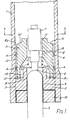
- Figure 1 of the drawings shows a cross-section view through one end of a high pressure sodium discharge arc lamp, the other end being substantially identical.
- the lamp comprises an arc tube 1 made of a light-transmissive ceramic material, e.g. polycrystalline alumina, fitted with a ceramic end plug 2 which is sintered to the arc tube wall (represented diagrammatically by broken line 3) to form a monolithic structure.
- a light-transmissive ceramic material e.g. polycrystalline alumina
- the end plug supports an electrode structure shown at 4 in side elevation.
- the electrode structure comprises a tubular lead-in member 5 (also shown in side elevation), made of niobium for example, and an electrode shank 6 which is mounted on the lead-in member and supports an over-wound electrode assembly 7 which may be impregnated with an emissive material. Both the electrode shank and the electrode assembly could be made of tungsten for example.
- the tubular lead-in member 5 extends through a central hole 8 in the end plug and is sealed therein by means of a glassy sealing material (layer 9), and it is this sealing material which can chemically combine with sodium in the arc tube resulting in a loss of sodium from the dose.
- the end closure is completed by provision of an end cap 10 which fills an annular space between the arc tube wall and the lead-in member.
- a different form of electrode structure could alternatively be used; for example, a lead-in member and an electrode-supporting shank set individually into a cermet end cap.
- a lead-in member and an electrode-supporting shank set individually into a cermet end cap.
- other forms of end closure can be envisaged.
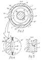
- the arc tube also includes a generally tubular insert member 11 which surrounds the electrode structure 4, as best seen in the end-on view of Figure 2.
- the insert member which is made of a ceramic material (STELLOX (RTM) in this example) and is sintered to the arc tube wall, has a plurality of channels each comprising two parts; a radially-extending part 12 formed in an outer end surface of the insert member and a longitudinally-extending part 13 formed in a side surface 14.
- the insert member has four such channels spaced at regular intervals around the electrode structure, though an alternative number of channels could be provided.
- each channel formed in the insert member has a part-circular cross-section.
- the insert member is conveniently formed by pressing, though alternative processing techniques e.g. machining or extruding could be used.
- Each channel in association with adjacent surfaces of the arc tube wall and end plug, defines a wick, having a longitudinally and a radially extending part, which is effective during operation of the lamp to move liquid dose, by capillary action, from a region R1 in a relatively cold part of the arc tube, adjacent to the end plug and the electrode seal, to a reservoir R2 located in a relatively hot part of the arc tube closer to the discharge arc.
- Reservoir R2 comprises a generally annular channel 15 defined by an internal surface of the arc tube wall and by an inwardly sloping surface 15′ formed at the inner end of the insert member, as illustrated in the longitudinal, sectional view of Figure 5.
- the longitudinally extending part of each wick opens into reservoir R2, and since channel 15 has a generally tapered cross-section it is effective as an additional wick to transfer dose, by capillary action, into, and along, the reservoir.
- the sloping side wall serves to maintain the level of liquid dose in the reservoir substantially constant.
- a central hole 16 in the insert member defines a passageway around the electrode structure which extends from the inner to the outer end surface.
- the passageway has a constricted inlet opening 17 and is wider at its outer end, adjacent to region R1.
- vapour evaporates from, and condenses at, the exposed surface S of liquid held in reservoir R2.
- the cross-sectional area of inlet opening 17 is made sufficiently small so as to ensure that the operating pressure in the arc tube is of the same order as the vapour pressure immediately above surface S, corresponding to the effective cool spot temperature at surface S.
- the cross-sectional area presented by the inlet opening approximately equals the area of exposed surface S.
- Each wick is effective to transfer liquid, by capillary action, from region R1 to reservoir R2, as represented by arrows A in Figure 1, and dose is returned to region R1, by vapour diffusion, as represented by arrows B.
- Liquid is otherwise retained in the reservoir by the effect of surface tension, and so the lamp can operate in any desired orientation.
- the supply of dose held in reservoir R2 should be maintained continually and, in order to promote a satisfactory circulation of dose, the distributions of temperature and vapour pressure along the passageway, illustrated qualitatively in Figure 3, are so tailored as to encourage vapour to condense in region R1, whilst allowing a desired lamp operating pressure in the main body of the arc tube to be achieved.
- vapour pressure in the passageway falls off rapidly in the direction approaching region R1, due to the constriction in the inlet 17.
- the temperature is held relatively high along a substantial part of the passageway, this being achieved by the close proximity of the ceramic insert member 11 to the hot electrode structure 4. This, in combination with the pressure distribution, tends to inhibit condensation of dose on the sides of the passageway.
- end plug 2 is configured to provide a short tubular wall 18 around the lead-in member 5. This wall prevents excess sealing material blocking the entrances to the wicks during lamp assembly and also promotes condensation of dose in region R1.
- the operating pressure in the arc tube does, of course, depend on the effective cool spot temperature at the exposed surface S of liquid in reservoir R2 which, in turn, depends on the level of liquid in the reservoir i.e. the proximity of surface S to the discharge arc.
- the inwardly sloping surface 15′ of channel 15 serves to reduce the effect of any volume change in the reservoir and thereby maintain the exposed surface S at a substantially constant level (and so cool spot temperature).
- each wick in this example of the invention has a generally lens-shaped, transverse cross-section, as is best seen in Figure 4 which illustrates, on an enlarged scale, a region identified at W in Figure 2.
- each lens-shaped wick is defined respectively by the surface of a channel 13, formed in the insert member, and by an inner surface of the arc tube wall.
- relatively small volumes of liquid occupy the narrow, edge regions E of the wick, as shown, and larger volumes occupy more of the central region C.
- the lens shape might have a width w of 2.2 mm, and a breadth b of 0.4 mm, the radii of curvature of sides 19, 20 being 3.0 mm and 3.7 mm respectively.
- Figures 6 to 8 of the drawings illustrate two alternative forms of wick configuration and where a component corresponds to that used in the configuration of Figure 1 it has been ascribed a like reference numeral.
- the insert member 11 includes four elongate parts 21 each having a convex, transverse cross-section and making contact with the arc tube wall thereby defining respective pairs of wicks (e.g. 22, 22′).
- Figures 7 and 8 show an arrangement wherein the insert member is in two parts.
- An upper part 23 which has four substantially lens-shaped wicks, is similar to that shown in Figures 1, 2, 4 and 5 and a lower part consists of four cylindrical rods 24 which are aligned with the lens-shaped wicks of the upper part and make line contact with the arc tube, again defining respective pairs of wicks 25, 25′ ( Figure 8).
- a discharge arc lamp in accordance with this invention has an effective cool spot temperature, at the exposed surface of liquid in the reservoir supplied by the wick, which is higher than the temperature at the ends of the arc tube and in the case of a high pressure sodium discharge arc lamp it is possible to achieve the relatively high operating pressure, as used in the SONDL lamp for example, but at a much lower seal temperature.
- the rate of chemical reaction between the glassy sealing material and sodium in the lamp dose is much reduced resulting in a lower rate of rise of lamp voltage through life, leading to longer life, and a reduction of colour change through life.
- the need for a heat shield, of the kind used in the SONDL lamp, is eliminated and the tolerancing associated with positioning the insert member in the arc tube is far less exacting than that associated with manufacture and assembly of discharge arc lamp configurations known hitherto.
- hitherto known lamps suffer from blackening at the ends of the arc tubes due to emitter material being thrown off by the electrode assembly and this tends to cause an undesirable increase in cool spot temperature giving rise to a change of lamp voltage and colour through life, in addition to the effect caused by sodium loss.
- the insert member tends to prevent blackening in the region of the reservoir R2, i.e. the effective cool spot, thereby reducing variation of both voltage and colour.
- the present invention has specific application to a high pressure sodium discharge arc lamp, particularly a high pressure sodium discharge arc lamp operating at the relatively high vapour pressures used in the SONDL lamp, the invention has wider applicability to discharge arc lamps generally, including sodium, mercury and metal halide lamps.
- a discharge arc lamp in accordance with the present invention can, by use of an insert member as defined, attain a higher cool spot temperature (and so vapour pressure) than could, in general, be attained using a hitherto known, commercially acceptable, lamp construction, thereby giving considerable scope for improved lamp design.
- a higher effective cool spot temperature could permit a reduction in the mercury content of the dose giving an improved voltage/power characteristic.
- a higher cool spot temperature could be used to achieve a relatively high colour rendering index, and it is believed, for example, that a colour rendering index in excess of 80 can be achieved in a high pressure sodium discharge lamp having an efficacy of between 40 and 45 lm/watt.
Landscapes
- Vessels And Coating Films For Discharge Lamps (AREA)
- Discharge Lamps And Accessories Thereof (AREA)
Description
- This invention relates to a discharge arc lamp and it relates particularly, though not exclusively, to a high pressure sodium discharge arc lamp.
- A known high pressure sodium discharge arc lamp, marketed by the Applicant company under the trade name SONDL, operates at a relatively high colour temperature (2150K) with a desirable colour rendering index, typically Ra = 65 .
- The SONDL operates at a relatively high vapour pressure requiring a high cool spot temperature. In the SONDL, this is achieved by provision of a heat shield around each end of the discharge arc tube near to a respective discharge electrode. In practice, it is found that the cool spot temperature depends critically on the length of heat shield used and on the size of a back-space between a discharge electrode and an adjacent end of the arc tube. The tolerancing required in manufacture, therefore, can be extremely exacting, leading to increased production costs. Furthermore, during lamp operation, variations in operating conditions such as lamp voltage, supply voltage and choke impedance may give rise to small yet significant fluctuations of lamp power. At the relatively high cool spot temperatures needed in the SONDL, the glassy sealing material used to seal the discharge electrodes to the ends of the arc tube can chemically combine with sodium in the lamp dose and increases of lamp power tend to exacerbate the problem. Progressively, over a period, sodium is removed from the dose reducing the Na mole fraction (nominally 0.744 in the case of the SONDL) in the arc tube and causing a gradual increase of lamp voltage, which eventually causes the lamp to cycle on and off and limits its useful life. Also, the colour of light emitted by the lamp changes, becoming pinker through life.
- One proposal for improving the situation has been made in EP-A-0 080 820. In this specification a reservoir for liquid dose is provided at a cooler region of an arc tube and a wick is provided, extending outwardly from the reservoir to transfer liquid dose from the reservoir to a relatively hotter region of the arc tube.
- The present invention seeks to provide a different form of discharge arc lamp construction which, in the case of a high pressure sodium discharge arc lamp, at least alleviates the problems described.
- According to a first aspect of the invention there is provided a discharge arc lamp including an arc tube containing a dose, an electrode structure sealed to each end of the arc tube, and a wick arranged to move liquid dose from a relatively cold region of the arc tube to a relatively hot region of the arc tube characterized by an insert member positioned between the wall of the arc tube and at least one said electrode structure wherein said insert member is arranged to define the wick which is effective, in operation of the lamp, to move liquid dose, by capillary action, from the relatively cold region of the arc tube adjacent to said end into a reservoir in the relatively hot region of the arc tube, and to further define a passageway allowing movement of dose, by vapour diffusion, to said relatively cold region, said wick being so configured as to accommodate a variable volume of liquid dose and said passageway being configured to enable attainment of a desired operating pressure in the arc tube, the distributions of vapour pressure and temperature along the passageway encouraging condensation of vapour at said relatively cold region such that the wick can maintain a substantially continuous supply of liquid dose at the reservoir.
- According to another aspect of the invention, there is provided an insert member as described above.
- A stable operating pressure is established, and maintained, in the arc tube by evaporation of liquid dose from said substantially continuous supply held in the reservoir, and the effective cool spot temperature of the lamp, at the surface of liquid in the reservoir, is significantly higher than the temperature at said end of the arc tube, where the electrode seal is located. Therefore, in the case of a high pressure sodium discharge arc lamp, the relatively cold seal material is less likely to combine chemically with sodium in the lamp dose giving a more stable lamp operation and longer lamp life. Moreover, the need for a specific heat shield, with its attendant tolerancing problems, is eliminated. Since the movement of dose is controlled by capillary action and by vapour diffusion the lamp can operate satisfactorily in any desired orientation, unlike other, hithertoknown forms of wick lamp.
- Said passageway may be located around said electrode structure and may have a constricted inlet enabling the operating vapour pressure in the arc tube to be of the same order as the vapour pressure immediately above the surface of the reservoir. Preferably, the cross-sectional area presented by the constricted inlet may be the same as, or similar to, the area of exposed surface of liquid dose held in said reservoir. In general, the ratio of the area of the exposed surface of dose to the cross-sectional area presented by the inlet should be greater than about 1/10, and preferably greater than 1/2, and can be as large as is practically possible.
- In order to accommodate a variable volume of liquid dose the wick may have a transverse cross-section of non-uniform width and, in particular, may be defined by adjacent, curved sides. The wick may have oppositely curved sides and, in an example, may have a generally lens-shaped cross-section defined by an inner surface of the arc tube wall and by the surface of a longitudinal channel formed in the insert member. The insert member may be arranged to define a plurality of wicks each having a longitudinally-extending part, and said reservoir may comprise an annular channel which is adapted to transfer dose, by capillary action, into the reservoir. Each wick may also have a radially-extending part which connects the respective longitudinally extending part to said relatively cold region of the arc tube. In order that the effective cool spot temperature of the lamp may be substantially independent of volume changes in the reservoir, the reservoir may be adapted to maintain therein a substantially constant level of liquid dose. Said transfer of dose and said maintenance of a substantially constant level may be accomplished by provision of a said channel having a sloping side wall.
- A wall may be provided around the electrode structure in the vicinity of the seal. The wall prevents excess sealing material blocking the entrances to the wicks during lamp assembly and also promotes condensation of dose in said relatively cold region of the arc tube near the entrances to the wicks.
- It will be appreciated that although the present invention has specific application to a high pressure sodium discharge arc lamp the invention has wider applicability to discharge arc lamps generally, including sodium, mercury and metal halide discharge arc lamps.
- In accordance with another aspect of the invention there is provided an insert member suitable for use in the arc tube of a discharge arc lamp according to said first aspect of the invention.
- In order that the invention may be carried readily into effect an embodiment thereof is now described, by way of example only, by reference to the accompanying drawings of which
- Figure 1 shows a longitudinal, cross-sectional view through one end of a high pressure sodium discharge arc lamp,
- Figure 2 shows a transverse, cross-sectional view of the lamp taken on line X-X in Figure 1,
- Figure 3 illustrates qualitativity the distributions of vapour pressure and temperature along a passageway in the lamp construction of Figures 1 and 2 and
- Figure 4 illustrates, on an enlarged scale, a region identified at W in Figure 2.
- Figure 5 shows a longitudinal cross-sectional view showing the detail on line Y-Y in Figure 1.
- Figure 6 shows a transverse, cross-sectional view through a discharge arc lamp having a differently configured insert member,
- Figure 7 shows a longitudinal, cross-sectional view through one end of a further, differently configured discharge arc lamp and Figure 8 shows a transverse, cross-sectional view taken on line ZZ in Figure 7.
- Figure 1 of the drawings shows a cross-section view through one end of a high pressure sodium discharge arc lamp, the other end being substantially identical.
- The lamp comprises an arc tube 1 made of a light-transmissive ceramic material, e.g. polycrystalline alumina, fitted with a
ceramic end plug 2 which is sintered to the arc tube wall (represented diagrammatically by broken line 3) to form a monolithic structure. - The end plug supports an electrode structure shown at 4 in side elevation. The electrode structure comprises a tubular lead-in member 5 (also shown in side elevation), made of niobium for example, and an
electrode shank 6 which is mounted on the lead-in member and supports an over-woundelectrode assembly 7 which may be impregnated with an emissive material. Both the electrode shank and the electrode assembly could be made of tungsten for example. - The tubular lead-in
member 5 extends through acentral hole 8 in the end plug and is sealed therein by means of a glassy sealing material (layer 9), and it is this sealing material which can chemically combine with sodium in the arc tube resulting in a loss of sodium from the dose. The end closure is completed by provision of anend cap 10 which fills an annular space between the arc tube wall and the lead-in member. - A different form of electrode structure could alternatively be used; for example, a lead-in member and an electrode-supporting shank set individually into a cermet end cap. Clearly, other forms of end closure can be envisaged.
- Referring now to Figures 1 and 2, the arc tube also includes a generally
tubular insert member 11 which surrounds the electrode structure 4, as best seen in the end-on view of Figure 2. The insert member, which is made of a ceramic material (STELLOX (RTM) in this example) and is sintered to the arc tube wall, has a plurality of channels each comprising two parts; a radially-extendingpart 12 formed in an outer end surface of the insert member and a longitudinally-extendingpart 13 formed in aside surface 14. In this example the insert member has four such channels spaced at regular intervals around the electrode structure, though an alternative number of channels could be provided. For reasons which will become apparent hereinafter, each channel formed in the insert member has a part-circular cross-section. - The insert member is conveniently formed by pressing, though alternative processing techniques e.g. machining or extruding could be used.
- Each channel, in association with adjacent surfaces of the arc tube wall and end plug, defines a wick, having a longitudinally and a radially extending part, which is effective during operation of the lamp to move liquid dose, by capillary action, from a region R₁ in a relatively cold part of the arc tube, adjacent to the end plug and the electrode seal, to a reservoir R₂ located in a relatively hot part of the arc tube closer to the discharge arc.
- Reservoir R₂ comprises a generally
annular channel 15 defined by an internal surface of the arc tube wall and by an inwardly slopingsurface 15′ formed at the inner end of the insert member, as illustrated in the longitudinal, sectional view of Figure 5. The longitudinally extending part of each wick opens into reservoir R₂, and sincechannel 15 has a generally tapered cross-section it is effective as an additional wick to transfer dose, by capillary action, into, and along, the reservoir. Also, as will be described in greater detail hereafter the sloping side wall serves to maintain the level of liquid dose in the reservoir substantially constant. - A
central hole 16 in the insert member defines a passageway around the electrode structure which extends from the inner to the outer end surface. The passageway has a constricted inlet opening 17 and is wider at its outer end, adjacent to region R₁. - During operation of the lamp, vapour evaporates from, and condenses at, the exposed surface S of liquid held in reservoir R₂. The cross-sectional area of
inlet opening 17 is made sufficiently small so as to ensure that the operating pressure in the arc tube is of the same order as the vapour pressure immediately above surface S, corresponding to the effective cool spot temperature at surface S. In an example, the cross-sectional area presented by the inlet opening approximately equals the area of exposed surface S. - Each wick is effective to transfer liquid, by capillary action, from region R₁ to reservoir R₂, as represented by arrows A in Figure 1, and dose is returned to region R₁, by vapour diffusion, as represented by arrows B. Liquid is otherwise retained in the reservoir by the effect of surface tension, and so the lamp can operate in any desired orientation. The supply of dose held in reservoir R₂ should be maintained continually and, in order to promote a satisfactory circulation of dose, the distributions of temperature and vapour pressure along the passageway, illustrated qualitatively in Figure 3, are so tailored as to encourage vapour to condense in region R₁, whilst allowing a desired lamp operating pressure in the main body of the arc tube to be achieved. To this end, vapour pressure in the passageway falls off rapidly in the direction approaching region R₁, due to the constriction in the
inlet 17. The temperature, however, is held relatively high along a substantial part of the passageway, this being achieved by the close proximity of theceramic insert member 11 to the hot electrode structure 4. This, in combination with the pressure distribution, tends to inhibit condensation of dose on the sides of the passageway. - In addition,
end plug 2 is configured to provide a shorttubular wall 18 around the lead-inmember 5. This wall prevents excess sealing material blocking the entrances to the wicks during lamp assembly and also promotes condensation of dose in region R₁. - The operating pressure in the arc tube does, of course, depend on the effective cool spot temperature at the exposed surface S of liquid in reservoir R₂ which, in turn, depends on the level of liquid in the reservoir i.e. the proximity of surface S to the discharge arc. The inwardly sloping
surface 15′ ofchannel 15 serves to reduce the effect of any volume change in the reservoir and thereby maintain the exposed surface S at a substantially constant level (and so cool spot temperature). - Particularly during lamp run-up, the dose may not be distributed evenly between the ends of the arc tube and so each wick should be capable of transferring a variable volume of liquid without interruption. To that end, each wick in this example of the invention, has a generally lens-shaped, transverse cross-section, as is best seen in Figure 4 which illustrates, on an enlarged scale, a region identified at W in Figure 2.
- The oppositely
curved sides channel 13, formed in the insert member, and by an inner surface of the arc tube wall. With a configuration of this kind, relatively small volumes of liquid occupy the narrow, edge regions E of the wick, as shown, and larger volumes occupy more of the central region C. In a typical example the lens shape might have a width w of 2.2 mm, and a breadth b of 0.4 mm, the radii of curvature ofsides - Figures 6 to 8 of the drawings illustrate two alternative forms of wick configuration and where a component corresponds to that used in the configuration of Figure 1 it has been ascribed a like reference numeral. Referring initially to Figure 6, the
insert member 11 includes fourelongate parts 21 each having a convex, transverse cross-section and making contact with the arc tube wall thereby defining respective pairs of wicks (e.g. 22, 22′). Figures 7 and 8 show an arrangement wherein the insert member is in two parts. Anupper part 23 which has four substantially lens-shaped wicks, is similar to that shown in Figures 1, 2, 4 and 5 and a lower part consists of fourcylindrical rods 24 which are aligned with the lens-shaped wicks of the upper part and make line contact with the arc tube, again defining respective pairs ofwicks - Other wick constructions will be apparent to those skilled in the art; it will be understood, for example, that any other way of configuring the inner surface of the arc tube wall and or the outer surface of the insert member which achieves a wicking action falls within the scope of the present invention.
- A discharge arc lamp in accordance with this invention has an effective cool spot temperature, at the exposed surface of liquid in the reservoir supplied by the wick, which is higher than the temperature at the ends of the arc tube and in the case of a high pressure sodium discharge arc lamp it is possible to achieve the relatively high operating pressure, as used in the SONDL lamp for example, but at a much lower seal temperature. The rate of chemical reaction between the glassy sealing material and sodium in the lamp dose is much reduced resulting in a lower rate of rise of lamp voltage through life, leading to longer life, and a reduction of colour change through life. Moreover, the need for a heat shield, of the kind used in the SONDL lamp, is eliminated and the tolerancing associated with positioning the insert member in the arc tube is far less exacting than that associated with manufacture and assembly of discharge arc lamp configurations known hitherto. In addition, hitherto known lamps suffer from blackening at the ends of the arc tubes due to emitter material being thrown off by the electrode assembly and this tends to cause an undesirable increase in cool spot temperature giving rise to a change of lamp voltage and colour through life, in addition to the effect caused by sodium loss. In the present invention the insert member tends to prevent blackening in the region of the reservoir R₂, i.e. the effective cool spot, thereby reducing variation of both voltage and colour.
- It will be understood that although the present invention has specific application to a high pressure sodium discharge arc lamp, particularly a high pressure sodium discharge arc lamp operating at the relatively high vapour pressures used in the SONDL lamp, the invention has wider applicability to discharge arc lamps generally, including sodium, mercury and metal halide lamps.
- It is believed that a discharge arc lamp in accordance with the present invention can, by use of an insert member as defined, attain a higher cool spot temperature (and so vapour pressure) than could, in general, be attained using a hitherto known, commercially acceptable, lamp construction, thereby giving considerable scope for improved lamp design.
- For example, a higher effective cool spot temperature could permit a reduction in the mercury content of the dose giving an improved voltage/power characteristic. Alternatively, a higher cool spot temperature could be used to achieve a relatively high colour rendering index, and it is believed, for example, that a colour rendering index in excess of 80 can be achieved in a high pressure sodium discharge lamp having an efficacy of between 40 and 45 lm/watt.
- Furthermore it is believed that a higher cool spot temperature may allow use of metals and metal halides in the dose which, on account of their low volatility, would be unsuitable for use in lamps of hitherto known construction.
Claims (13)
- A discharge arc lamp including an arc tube (1) containing a dose, an electrode structure (4) sealed to each end of the arc tube (1), and a wick (12,13) arranged to move liquid dose from a relatively cold region (R1) of the arc tube to a relatively hot region (R2) of the arc tube (1) characterized by an insert member (11,23,24) positioned between the wall of the arc tube (1) and at least one said electrode structure (4) wherein said insert member (11,23,24) is arranged to define the wick (12,13) which is effective, in operation of the lamp, to move liquid dose, by capillary action, from the relatively cold region (R1) of the arc tube (1) adjacent to said end into a reservoir (15) in the relatively hot region (R2) of the arc tube (1), and to further define a passageway (16) allowing movement of dose, by vapour diffusion, to said relatively cold region (R1), said wick (12,13) being so configured as to accommodate a variable volume of liquid dose and said passageway (16) being configured to enable attainment of a desired operating pressure in the arc tube (1), the distributions of vapour pressure and temperature along the passageway (16) encouraging condensation of vapour at said relatively cold region (R1) such that the wick (12,13) can maintain a substantially continuous supply of liquid dose at the reservoir (15).
- A discharge arc lamp according to Claim 1 wherein said passageway (16) is located around said electrode structure (4) and has a constricted inlet (17) enabling the operating vapour pressure in the arc tube (1) to be of the same order as the vapour pressure immediately above the surface of the reservoir (15).
- A discharge arc lamp according to Claim 2 wherein the cross-sectional area of said constricted inlet (17) is the same as, or similar to, the area of the exposed surface (5) of liquid dose held in said reservoir (15).
- A discharge arc lamp according to any one of Claims 1 to 3 wherein said wick (12,13) has a transverse cross-section of non-uniform width.
- A discharge arc lamp according to Claim 4 wherein said wick (12,13) has a generally lens-shaped cross-section defined by an inner surface of the arc tube wall and by the surface of a longitudinal channel formed in the insert member (11,23,24).
- A discharge arc lamp according to any one of Claims 1 to 5 wherein the insert member (11,23,24) is arranged to define a plurality of wicks (12,13), each having a longitudinally-extending part (13), and said reservoir (15) comprises an annular channel which is adapted to transfer dose, by capillary action, into the reservoir (5).
- A discharge arc lamp according to any one of Claims 1 to 6 wherein said reservoir (15) is adapted to maintain therein a substantially constant level of liquid dose.
- A discharge arc lamp according to Claim 6 and Claim 7 wherein said annular channel (15) has a sloping side wall (15′) thereby to effect said transfer and maintain said substantially constant level.
- A discharge arc lamp according to any one of Claims 6 to 8 wherein each one of said plurality of wicks (12,13) has a radially-extending part (12) which connects the respective longitudinally-extending part (13) to said relatively cold region (R1) of the arc tube (1).
- A discharge arc lamp according to any one of Claims 1 to 9 including a barrier (18) around the electrode structure (4).
- A ceramic discharge arc lamp according to any one of Claims 1 to 10.
- A high pressure sodium discharge arc lamp according to any one of Claims 1 to 11.
- An insert member (11,23,24) having all the features of the insert member described in Claim 1, adapted to be used in the arc tube (1) of a discharge arc lamp according to any one of Claims 1 to 12.
Applications Claiming Priority (2)
| Application Number | Priority Date | Filing Date | Title |
|---|---|---|---|
| GB878725912A GB8725912D0 (en) | 1987-11-05 | 1987-11-05 | Discharge arc lamp |
| GB8725912 | 1987-11-05 |
Publications (3)
| Publication Number | Publication Date |
|---|---|
| EP0315445A2 EP0315445A2 (en) | 1989-05-10 |
| EP0315445A3 EP0315445A3 (en) | 1991-01-23 |
| EP0315445B1 true EP0315445B1 (en) | 1994-11-23 |
Family
ID=10626475
Family Applications (1)
| Application Number | Title | Priority Date | Filing Date |
|---|---|---|---|
| EP19880310343 Expired - Lifetime EP0315445B1 (en) | 1987-11-05 | 1988-11-03 | Discharge arc lamp |
Country Status (3)
| Country | Link |
|---|---|
| EP (1) | EP0315445B1 (en) |
| DE (1) | DE3852169T2 (en) |
| GB (1) | GB8725912D0 (en) |
Family Cites Families (4)
| Publication number | Priority date | Publication date | Assignee | Title |
|---|---|---|---|---|
| GB526401A (en) * | 1939-03-15 | 1940-09-17 | Siemens Electric Lamps & Suppl | Improvements relating to electric discharge lamps |
| EP0080820A3 (en) * | 1981-11-27 | 1983-12-14 | Thorn Emi Plc | Improvements in or relating to discharge lamps |
| CA1209193A (en) * | 1982-11-26 | 1986-08-05 | General Electric Company | High pressure sodium lamp having improved coloring rendition |
| US4868457A (en) * | 1985-01-14 | 1989-09-19 | General Electric Company | Ceramic lamp end closure and inlead structure |
-
1987
- 1987-11-05 GB GB878725912A patent/GB8725912D0/en active Pending
-
1988
- 1988-11-03 EP EP19880310343 patent/EP0315445B1/en not_active Expired - Lifetime
- 1988-11-03 DE DE19883852169 patent/DE3852169T2/en not_active Expired - Fee Related
Also Published As
| Publication number | Publication date |
|---|---|
| EP0315445A2 (en) | 1989-05-10 |
| GB8725912D0 (en) | 1987-12-09 |
| EP0315445A3 (en) | 1991-01-23 |
| DE3852169D1 (en) | 1995-01-05 |
| DE3852169T2 (en) | 1995-07-13 |
Similar Documents
| Publication | Publication Date | Title |
|---|---|---|
| US5138228A (en) | Bulb geometry for low power metal halide lamp | |
| US5142195A (en) | Pinch-sealed high pressure discharge lamp, and method of its manufacture | |
| JP2858777B2 (en) | Powerful discharge lamp | |
| US5471110A (en) | High pressure discharge lamp having filament electrodes | |
| US5083059A (en) | Electrode for metal halide discharge lamp | |
| EP0581359B1 (en) | HID lamp having an arc tube with offset press seals | |
| EP0645800B1 (en) | High pressure discharge lamp | |
| KR20030043696A (en) | High-pressure gas discharge lamp | |
| US5117154A (en) | Metal halide discharge lamp with improved shank loading factor | |
| EP0315445A2 (en) | Discharge arc lamp | |
| US6786791B2 (en) | Quartz arc tube for a metal halide lamp and method of making same | |
| CA1243721A (en) | Dischage lamp arc tube having opposite hemispherical ends and an intermediate conical region | |
| KR200170646Y1 (en) | High-pressure discharge lamp and associated illuminating system | |
| US6617790B2 (en) | Metal halide lamp with ceramic discharge vessel | |
| JPH02106866A (en) | High voltage discharge lamp | |
| US4475058A (en) | Discharge lamp having convoluted discharge path | |
| JPH0711944B2 (en) | Asymmetric arc chamber for discharge lamps | |
| US4700107A (en) | High-pressure discharge lamp having a tungsten sheet electrode | |
| CA2453700A1 (en) | Gas discharge lamp | |
| JP3846282B2 (en) | Short arc type high pressure discharge lamp | |
| US5211595A (en) | Method of manufacturing an arc tube with offset press seals | |
| US4614890A (en) | High intensity discharge lamp alkali metal loss reduction means | |
| GB1561919A (en) | High pressure vapour discharge lamp | |
| JP2010539663A (en) | High pressure discharge lamp | |
| US4459513A (en) | High pressure sodium vapor lamp having resistance heater means |
Legal Events
| Date | Code | Title | Description |
|---|---|---|---|
| PUAI | Public reference made under article 153(3) epc to a published international application that has entered the european phase |
Free format text: ORIGINAL CODE: 0009012 |
|
| AK | Designated contracting states |
Kind code of ref document: A2 Designated state(s): DE FR GB NL |
|
| PUAL | Search report despatched |
Free format text: ORIGINAL CODE: 0009013 |
|
| AK | Designated contracting states |
Kind code of ref document: A3 Designated state(s): DE FR GB NL |
|
| 17P | Request for examination filed |
Effective date: 19910318 |
|
| RAP1 | Party data changed (applicant data changed or rights of an application transferred) |
Owner name: GE LIGHTING LIMITED |
|
| 17Q | First examination report despatched |
Effective date: 19930701 |
|
| GRAA | (expected) grant |
Free format text: ORIGINAL CODE: 0009210 |
|
| AK | Designated contracting states |
Kind code of ref document: B1 Designated state(s): DE FR GB NL |
|
| ET | Fr: translation filed | ||
| REF | Corresponds to: |
Ref document number: 3852169 Country of ref document: DE Date of ref document: 19950105 |
|
| PLBE | No opposition filed within time limit |
Free format text: ORIGINAL CODE: 0009261 |
|
| STAA | Information on the status of an ep patent application or granted ep patent |
Free format text: STATUS: NO OPPOSITION FILED WITHIN TIME LIMIT |
|
| 26N | No opposition filed | ||
| PG25 | Lapsed in a contracting state [announced via postgrant information from national office to epo] |
Ref country code: NL Effective date: 19960601 |
|
| NLV4 | Nl: lapsed or anulled due to non-payment of the annual fee |
Effective date: 19960601 |
|
| REG | Reference to a national code |
Ref country code: GB Ref legal event code: IF02 |
|
| PGFP | Annual fee paid to national office [announced via postgrant information from national office to epo] |
Ref country code: DE Payment date: 20021202 Year of fee payment: 15 |
|
| PGFP | Annual fee paid to national office [announced via postgrant information from national office to epo] |
Ref country code: GB Payment date: 20031029 Year of fee payment: 16 |
|
| PGFP | Annual fee paid to national office [announced via postgrant information from national office to epo] |
Ref country code: FR Payment date: 20031119 Year of fee payment: 16 |
|
| PG25 | Lapsed in a contracting state [announced via postgrant information from national office to epo] |
Ref country code: DE Free format text: LAPSE BECAUSE OF NON-PAYMENT OF DUE FEES Effective date: 20040602 |
|
| PG25 | Lapsed in a contracting state [announced via postgrant information from national office to epo] |
Ref country code: GB Free format text: LAPSE BECAUSE OF NON-PAYMENT OF DUE FEES Effective date: 20041103 |
|
| GBPC | Gb: european patent ceased through non-payment of renewal fee |
Effective date: 20041103 |
|
| PG25 | Lapsed in a contracting state [announced via postgrant information from national office to epo] |
Ref country code: FR Free format text: LAPSE BECAUSE OF NON-PAYMENT OF DUE FEES Effective date: 20050729 |
|
| REG | Reference to a national code |
Ref country code: FR Ref legal event code: ST |