EP0315273A1 - Circuit arrangement for controlling alternating current by a load - Google Patents
Circuit arrangement for controlling alternating current by a load Download PDFInfo
- Publication number
- EP0315273A1 EP0315273A1 EP88202440A EP88202440A EP0315273A1 EP 0315273 A1 EP0315273 A1 EP 0315273A1 EP 88202440 A EP88202440 A EP 88202440A EP 88202440 A EP88202440 A EP 88202440A EP 0315273 A1 EP0315273 A1 EP 0315273A1
- Authority
- EP
- European Patent Office
- Prior art keywords
- circuit arrangement
- terminal
- capacitor
- triac
- voltage
- Prior art date
- Legal status (The legal status is an assumption and is not a legal conclusion. Google has not performed a legal analysis and makes no representation as to the accuracy of the status listed.)
- Ceased
Links
Images
Classifications
-
- H—ELECTRICITY
- H03—ELECTRONIC CIRCUITRY
- H03K—PULSE TECHNIQUE
- H03K17/00—Electronic switching or gating, i.e. not by contact-making and –breaking
- H03K17/28—Modifications for introducing a time delay before switching
- H03K17/292—Modifications for introducing a time delay before switching in thyristor, unijunction transistor or programmable unijunction transistor switches
-
- H—ELECTRICITY
- H02—GENERATION; CONVERSION OR DISTRIBUTION OF ELECTRIC POWER
- H02P—CONTROL OR REGULATION OF ELECTRIC MOTORS, ELECTRIC GENERATORS OR DYNAMO-ELECTRIC CONVERTERS; CONTROLLING TRANSFORMERS, REACTORS OR CHOKE COILS
- H02P25/00—Arrangements or methods for the control of AC motors characterised by the kind of AC motor or by structural details
- H02P25/02—Arrangements or methods for the control of AC motors characterised by the kind of AC motor or by structural details characterised by the kind of motor
- H02P25/10—Commutator motors, e.g. repulsion motors
- H02P25/14—Universal motors
-
- H—ELECTRICITY
- H02—GENERATION; CONVERSION OR DISTRIBUTION OF ELECTRIC POWER
- H02M—APPARATUS FOR CONVERSION BETWEEN AC AND AC, BETWEEN AC AND DC, OR BETWEEN DC AND DC, AND FOR USE WITH MAINS OR SIMILAR POWER SUPPLY SYSTEMS; CONVERSION OF DC OR AC INPUT POWER INTO SURGE OUTPUT POWER; CONTROL OR REGULATION THEREOF
- H02M1/00—Details of apparatus for conversion
- H02M1/08—Circuits specially adapted for the generation of control voltages for semiconductor devices incorporated in static converters
- H02M1/083—Circuits specially adapted for the generation of control voltages for semiconductor devices incorporated in static converters for the ignition at the zero crossing of the voltage or the current
Definitions
- the invention relates to a circuit arrangement for controlling the alternating current through a load a terminal of which is connected to a first power supply terminal, said circuit arrangement being connected during operation between the other load terminal and the other power supply terminal and comprising a series circuit of a resistor section and a capacitor section connected between the other load terminal and the other power supply terminal, and a controlled rectifier connected between the other load terminal and the other power supply terminal, the control current for the controlled rectifier being taken via a diac from the junction point between the resistor section and the capacitor section.
- a circuit arrangement of this type is known, for example, from Netherlands Patent Application 7003842. If such relatively simple circuit arrangements are used for, for example, controlling a motor or the like, electronic components will generally be used which have a relatively large tolerance in their electrical specification. The result is that at least a control component, for example, a potentiometer is required to control the minimum phase angle of the phase control of the controlled rectifier to the desired value. This control component must be adjusted to the correct value in a control procedure which is considered to be a serious drawback particularly in the case of series manufacture of large numbers of such circuit arrangements.
- this object is realized in that a further controlled rectifier is connected between the control terminal of the first-mentioned controlled rectifier and the junction point between the resistor section and the capacitor section, and in that the diac is connected between the last-mentioned junction point and the control terminal of the further controlled rectifier.
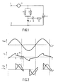
- Figure 1 shows a generally known circuit arrangement for controlling a load, constructed as a motor in this case.
- the AC power supply for the motor 3, for example, the mains voltage is presented to the power supply terminals 1 and 2.
- a terminal of the motor is connected to the mains terminal 1, whilst the other terminal is connected to a controlled rectifier circuit, in this case a triac 7, and is connected to a resistor section comprising a trimming potentiometer 4 and a control potentiometer 5.
- the two potentiometers 4 and 5 are parallel arranged.
- a capacitor 6 the other terminal of which is connected to the other power supply terminal 2 is arranged in series with this parallel arrangement.
- a diac 8 supplying the control current for the control input of the triac 7 via a current limiting resistor 9 is connected to the junction point of the parallel arrangement of the resistors 4 and 5 and the capacitor 6.
- Figure 2 shows the waveform of the power supply voltage U net at the terminals 1 and 2.
- Figure 2b shows the waveform of the voltage U c across the capacitor 6.
- Figure 2c shows the waveform of the current I m through the motor and the waveform of the voltage U m across the motor.
- V p voltage drop
- V p voltage at the junction point between capacitor 6 and the two resistors 4 and 5
- V p voltage at the junction point between capacitor 6 and the two resistors 4 and 5
- V p voltage at the junction point between capacitor 6 and the two resistors 4 and 5
- V p voltage at the junction point between capacitor 6 and the two resistors 4 and 5
- V p voltage at the junction point between capacitor 6 and the two resistors 4 and 5
- V p the voltage at the junction point between capacitor 6 and the two resistors 4 and 5 will decrease by V p , which becomes manifest in the waveform of the voltage U c across the capacitor 6, Figure 2b.
- this capacitor voltage will be reduced stepwise by V p .
- the diac 8 breaks down so that a current starts to flow through the control input of the triac 7 which thereby becomes conducting.
- the now conducting triac 7 has a substantially negligible resistance and its result is that, considered electronically, the capacitor 6 is placed across the parallel arrangement of the resistors 4 and 5 and will now be discharged across these resistors.
- U c U t1 (1-e -t/RC ) wherein: U t1 is the voltage across the capacitor at the instant t1, c is the capacitance of capacitor 6 and R is the resistance of the parallel resistors 4 and 5.
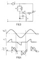
- Figure 3 shows a modified circuit arrangement which does not require any control.
- the components which are also present in the circuit arrangement of Figure 1 have the same reference numerals.
- the ignition current for the triac 7 is not supplied via the diac 8 and the resistor 9, but via a further triac whose control terminal is fed by the diac 8.
- This triac 10 then controls the control terminal of the triac 7 via the current limiting resistor 9.
- the trimming potentiometer 4 of Figure 1 is replaced by a fixed resistor 14 in this circuit arrangement.
- Figure 4a shows the waveform of the power supply voltage U net .
- Figure 4b shows the waveform of the voltage U across the capacitor 6.
- Figure 4c shows the waveform of the current I through the motor 3 and the voltage U c across the motor 3.
- the capacitor 6 is charged via the parallel resistors 5 and 14 until the breakdown voltage of the diac 8 has been reached at the instant t4. Due to the diac 8 becoming conducting the triac 10 will be rendered conducting and in its turn it supplies the control current for rendering the triac 7 conducting via the resistor 9.
- a resistor 11 between the control input of the triac 10 and the power supply terminal 2. This resistor is shown in a broken line in Figure 3.
- the resistor 9 does not play an essential role in the operation of the circuit arrangement and may be dispensed with in many cases without any problem.
Abstract
A motor (3) is arranged in series with a first triac (7) between two terminals (1, 2) for connection to a mains voltage. The series circuit of a capacitor (6) and the parallel circuit of a first (14) and a second (5) resistor is arranged parallel to the first triac (7). The control electrode of the first triac (7) is connected to the capacitor (6) by means of the series circuit of a third resistor (9) and a second triac (10). The control electrode of the second triac (10) is connected to the capacitor (6) by means of a diac (8).
Description
- The invention relates to a circuit arrangement for controlling the alternating current through a load a terminal of which is connected to a first power supply terminal, said circuit arrangement being connected during operation between the other load terminal and the other power supply terminal and comprising a series circuit of a resistor section and a capacitor section connected between the other load terminal and the other power supply terminal, and a controlled rectifier connected between the other load terminal and the other power supply terminal, the control current for the controlled rectifier being taken via a diac from the junction point between the resistor section and the capacitor section.
- A circuit arrangement of this type is known, for example, from Netherlands Patent Application 7003842. If such relatively simple circuit arrangements are used for, for example, controlling a motor or the like, electronic components will generally be used which have a relatively large tolerance in their electrical specification. The result is that at least a control component, for example, a potentiometer is required to control the minimum phase angle of the phase control of the controlled rectifier to the desired value. This control component must be adjusted to the correct value in a control procedure which is considered to be a serious drawback particularly in the case of series manufacture of large numbers of such circuit arrangements.
- It is an object of the invention to indicate the manner in which the circuit arrangement must be constructed in order to avoid the use of control components without the relatively large tolerances in the electric components used having a detrimental influence on the operation of the circuit arrangement.
- In a circuit arrangement of the type described in the opening paragraph this object is realized in that a further controlled rectifier is connected between the control terminal of the first-mentioned controlled rectifier and the junction point between the resistor section and the capacitor section, and in that the diac is connected between the last-mentioned junction point and the control terminal of the further controlled rectifier.
- The invention will now be described in greater detail, by way of example, with reference to the accompanying drawings in which
- Figure 1 is a general circuit diagram of a known circuit arrangement with reference to which the drawbacks of this circuit arrangement will be explained,
- Figure 2 shows some waveforms of voltages and currents occurring in the circuit arrangement of Figure 1,
- Figure 3 shows a circuit arrangement in conformity with the principle of the invention,
- Figure 4 shows voltages and currents occurring in the circuit arrangement of Figure 3.
- Figure 1 shows a generally known circuit arrangement for controlling a load, constructed as a motor in this case. The AC power supply for the
motor 3, for example, the mains voltage is presented to thepower supply terminals 1 and 2. A terminal of the motor is connected to the mains terminal 1, whilst the other terminal is connected to a controlled rectifier circuit, in this case a triac 7, and is connected to a resistor section comprising a trimming potentiometer 4 and a control potentiometer 5. The two potentiometers 4 and 5 are parallel arranged. Acapacitor 6 the other terminal of which is connected to the otherpower supply terminal 2 is arranged in series with this parallel arrangement. Adiac 8 supplying the control current for the control input of the triac 7 via a current limitingresistor 9 is connected to the junction point of the parallel arrangement of the resistors 4 and 5 and thecapacitor 6. - The operation of the circuit arrangement of Figure 1 will be briefly desribed with reference to Figure 2 in which a number of current and voltage waveforms of currents and voltages in the circuit arrangement of Figure 1 have been illustrated. Particularly Figure 2a shows the waveform of the power supply voltage Unet at the
terminals 1 and 2. Figure 2b shows the waveform of the voltage Uc across thecapacitor 6. Figure 2c shows the waveform of the current Im through the motor and the waveform of the voltage Um across the motor. - It is apparent from Figure 2 that during the positive mains voltage period and as long as the triac 7 is not yet conducting, the
capacitor 6 will be charged via the parallel arrangement of the resistors 4 and 5 until the breakdown voltage of thediac 8 is reached. The capacitor voltage Uc thus increases gradually. The current through themotor 3 is negligible and also the voltage across themotor 3, which represents only a small impedanceas compared with the resistors 4 and 5, is substantially equal to zero. - At the instant when the
diac 8 breaks down a voltage drop Vp is produced across this diac, which drop generally has a value varying between 5 and 15 V for the conventional types of diacs. Due to this voltage drop Vp the voltage at the junction point betweencapacitor 6 and the two resistors 4 and 5 will decrease by Vp, which becomes manifest in the waveform of the voltage Uc across thecapacitor 6, Figure 2b. At the instant t₁ this capacitor voltage will be reduced stepwise by Vp. - At the instant t₁ the
diac 8 breaks down so that a current starts to flow through the control input of the triac 7 which thereby becomes conducting. The now conducting triac 7 has a substantially negligible resistance and its result is that, considered electronically, thecapacitor 6 is placed across the parallel arrangement of the resistors 4 and 5 and will now be discharged across these resistors. - The voltage across the capacitor therefore decreases in accordance with an e power: Uc = Ut1(1-e-t/RC) wherein: Ut1 is the voltage across the capacitor at the instant t₁,
c is the capacitance ofcapacitor 6 and
R is the resistance of the parallel resistors 4 and 5. - At the instant t₁ the instantaneous mains voltage will be completely present across the
motor 3 due to the triac 7 becoming conducting, as is apparent from Figure 2c. Consequently, the current Im will flow through themotor 3 as is also indicated in Figure 2c. At the instant t₃ at which the motor current Im passes through zero and the triac 7 is thus blocked, the voltage across thecapacitor 6 is generally not yet equal to zero. As will be evident from the above, the residual voltage at the instant t₃ is dependent on the value of Vp, on the capacitance of thecapacitor 6 and on the resistances of the resistors 4 and 5. However, this residual voltage constitutes the starting condition for the next charge period of the capacitor and is thus also decisive of the instant at which the triac 7 is rendered conducting again. Since the voltage Vp across thediac 8 can vary within ample limits dependent on components and since also the tolerance of the control potentiometer 5 in the case of normal components is relatively large (± 12%), a considerable spread in the instant at which the triac 7 is rendered conducting will occur in the case of series manufacture of such circuit arrangements. Therefore it is necessary to perform a control by means of the trimming potentiometer 4 in such a way that this spread in the different series-manufactured circuit arrangements is at least considerably reduced. However, it is considered to be a drawback to perform such a control procedure. It is true that very accurate components having small tolerances could be used, but this generally has a considerable cost-price increasing effect and thus actually does not provide a solution to the signalized problems. - In conformity with the invention, Figure 3 shows a modified circuit arrangement which does not require any control. The components which are also present in the circuit arrangement of Figure 1 have the same reference numerals. In the circuit arrangement of Figure 3 the ignition current for the triac 7 is not supplied via the
diac 8 and theresistor 9, but via a further triac whose control terminal is fed by thediac 8. Thistriac 10 then controls the control terminal of the triac 7 via the current limitingresistor 9. As will be explained hereinafter, the trimming potentiometer 4 of Figure 1 is replaced by afixed resistor 14 in this circuit arrangement. - The operation of the circuit arrangement of Figure 3 will be described with reference to the diagrams of Figure 4. Figure 4a shows the waveform of the power supply voltage Unet. Figure 4b shows the waveform of the voltage U across the
capacitor 6. Figure 4c shows the waveform of the current I through themotor 3 and the voltage Uc across themotor 3. - The
capacitor 6 is charged via theparallel resistors 5 and 14 until the breakdown voltage of thediac 8 has been reached at the instant t₄. Due to thediac 8 becoming conducting thetriac 10 will be rendered conducting and in its turn it supplies the control current for rendering the triac 7 conducting via theresistor 9. - Due to the
triac 10 becoming conducting a very low-ohmic discharge path is produced for thecapacitor 6, which path extends via theconducting triac 10, the very low-ohmic resistor 9 and the control terminal of the triac 7. Consequently, thecapacitor 6 will be discharged very rapidly, as is also apparent from Figure 4b. - At t₄ the instantaneous power supply voltage is applied across the
motor 3, and the current Im through the motor will start flowing in the way as has been illustrated in Figure 4c. At the instant t₅ at which the motor current crosses zero, thecapacitor 6 has been fully discharged. Charging of the capacitor thus always begins from the same initial starting voltage of 0 volt and is thus independent of the value of the voltage Vp across thediac 8 and independent of the value of the resistors in the resistor section. - To prevent the
triac 10 from being rendered conducting too early due to interference pulses, it is preferable to arrange aresistor 11 between the control input of thetriac 10 and thepower supply terminal 2. This resistor is shown in a broken line in Figure 3. - It will be evident that tolerances in the capacitance of the
capacitor 6 and in the resistances of theresistors 5 and 14 still play a role when thecapacitor 6 is being charged and thereby influence the instant t₄ at which the breakdown voltage of thediac 8 is reached. However, this influence is considerably smaller than in the known circuit arrangement according to Figure 1 and no longer requires the use of a trimming potentiometer which must be trimmed in a separate procedure. - The circuit arrangement of Figure 3 has been tested in practice in a 220 V, 50 Hz AC motor with a nominal power of 110 W. When using a
capacitor 6 having a tolerance of ± 2%, a control potentiometer having a tolerance of ± 12% andresistors 4 and 11 having a tolerance of ± 2%, the tolerance of the minimum phase angle was found to be equal to 0.2 msec, which, related to the nominal power of the motor, implies a power control tolerance of ± 50 W. In many applications, for example, in domestic appliances such a tolerance is acceptable without any problem. - Although in the circuit arrangement of Figure 3 a triac is used for the controlled
rectifiers 7 and 10, it is alternatively possible to use the principle of the invention in a circuit arrangement in which thyristors are used as controlledrectifiers 7 and 10. - Finally, it is to be noted that the
resistor 9 does not play an essential role in the operation of the circuit arrangement and may be dispensed with in many cases without any problem.
Claims (3)
1. A circuit arrangement for controlling the alternating current through a load a terminal of which is connected to a first power supply terminal, said circuit arrangement being connected during operation between the other load terminal and the other power supply terminal and comprising a series circuit of a resistor section and a capacitor section connected between the other load terminal and the other power supply terminal, and a controlled rectifier connected between the other load terminal and the other power supply terminal, the control current for the controlled rectifier being taken via a diac from the junction point between the resistor section and the capacitor section, characterized in that a further controlled rectifier is connected between the control terminal of the first-mentioned controlled rectifier and the junction point between the resistor section and the capacitor section, and in that the diac is connected between the last-mentioned junction point and the control terminal of the further controlled rectifier.
2. A circuit arrangement as claimed in Claim 1, characterized in that the control terminal of the further controlled rectifier is connected via a resistor to the other mains terminal.
3. A circuit arrangement as claimed in Claim 1 or 2, characterized in that the controlled rectifiers consist of triacs.
Applications Claiming Priority (2)
| Application Number | Priority Date | Filing Date | Title |
|---|---|---|---|
| NL8702645 | 1987-11-05 | ||
| NL8702645 | 1987-11-05 |
Publications (1)
| Publication Number | Publication Date |
|---|---|
| EP0315273A1 true EP0315273A1 (en) | 1989-05-10 |
Family
ID=19850871
Family Applications (1)
| Application Number | Title | Priority Date | Filing Date |
|---|---|---|---|
| EP88202440A Ceased EP0315273A1 (en) | 1987-11-05 | 1988-11-01 | Circuit arrangement for controlling alternating current by a load |
Country Status (5)
| Country | Link |
|---|---|
| US (1) | US4914327A (en) |
| EP (1) | EP0315273A1 (en) |
| JP (1) | JPH01152954A (en) |
| KR (1) | KR890009091A (en) |
| DK (1) | DK610088A (en) |
Cited By (3)
| Publication number | Priority date | Publication date | Assignee | Title |
|---|---|---|---|---|
| FR2819102A1 (en) * | 2000-12-29 | 2002-07-05 | St Microelectronics Sa | BISTABLE BISTABLE ELECTRONIC SWITCH WITH PULSE CONTROL |
| WO2003005555A1 (en) * | 2001-07-05 | 2003-01-16 | Diehl Ako Stiftung & Co. Kg | Rotational speed control for a universal motor having a reduced fluctuation of current |
| EP2154774A1 (en) | 2008-08-12 | 2010-02-17 | ABB Oy | Method of controlling a rectifying bridge in a diode mode and a circuit for the control |
Families Citing this family (8)
| Publication number | Priority date | Publication date | Assignee | Title |
|---|---|---|---|---|
| US5247230A (en) * | 1992-06-02 | 1993-09-21 | Lucerne Products, Inc. | Unilateral diac for motor speed control |
| US5363534A (en) * | 1992-06-19 | 1994-11-15 | U.S. Philips Corporation | Vacuum cleaner and suction tube for use with a vacuum cleaner |
| US5619081A (en) * | 1994-01-18 | 1997-04-08 | Leviton Manufacturing Co., Inc. | Asymmetrical AC trigger simulation |
| US5512810A (en) * | 1994-05-27 | 1996-04-30 | Eaton Corporation | Variable speed control for a hand-held electric power tool |
| US6226830B1 (en) | 1997-08-20 | 2001-05-08 | Philips Electronics North America Corp. | Vacuum cleaner with obstacle avoidance |
| US6188214B1 (en) * | 2000-02-18 | 2001-02-13 | Pass & Seymour, Inc. | Phase control switch with reduced heat dissipating RFI inductor |
| WO2006133173A1 (en) * | 2005-06-06 | 2006-12-14 | Lutron Electronics Co., Inc. | Power supply for a load control device |
| US7728564B2 (en) * | 2005-06-06 | 2010-06-01 | Lutron Electronics Co., Inc. | Power supply for a load control device |
Citations (3)
| Publication number | Priority date | Publication date | Assignee | Title |
|---|---|---|---|---|
| BE641816A (en) * | ||||
| FR1390166A (en) * | 1962-12-29 | 1965-02-26 | Texas Instruments Inc | Control circuit for a series motor |
| NL7003842A (en) * | 1970-03-18 | 1971-09-21 |
Family Cites Families (6)
| Publication number | Priority date | Publication date | Assignee | Title |
|---|---|---|---|---|
| US3484623A (en) * | 1966-04-13 | 1969-12-16 | Hunt Electronics Co | Power control circuit using bistable switching device |
| US3619656A (en) * | 1970-02-27 | 1971-11-09 | Motorola Inc | Bilateral voltage responsive switch |
| US3729651A (en) * | 1971-04-07 | 1973-04-24 | Ecc Corp | Voltage regulator |
| US3798470A (en) * | 1972-12-15 | 1974-03-19 | Gte Automatic Electric Lab Inc | Selective d.c. isolation circuit |
| US4069446A (en) * | 1974-11-30 | 1978-01-17 | Sanwa Chemical Co., Ltd. | Speed control means for AC motor |
| US4353025A (en) * | 1980-12-08 | 1982-10-05 | Hybrinetics, Inc. | Phase controlled voltage reducing circuit having line voltage compensation |
-
1988
- 1988-11-01 EP EP88202440A patent/EP0315273A1/en not_active Ceased
- 1988-11-01 US US07/265,658 patent/US4914327A/en not_active Expired - Fee Related
- 1988-11-02 JP JP63276331A patent/JPH01152954A/en active Pending
- 1988-11-02 KR KR1019880014358A patent/KR890009091A/en not_active Application Discontinuation
- 1988-11-02 DK DK610088A patent/DK610088A/en not_active Application Discontinuation
Patent Citations (3)
| Publication number | Priority date | Publication date | Assignee | Title |
|---|---|---|---|---|
| BE641816A (en) * | ||||
| FR1390166A (en) * | 1962-12-29 | 1965-02-26 | Texas Instruments Inc | Control circuit for a series motor |
| NL7003842A (en) * | 1970-03-18 | 1971-09-21 |
Non-Patent Citations (1)
| Title |
|---|
| PATENT ABSTRACTS OF JAPAN vol. 10, no. 263 (E-435) 2319 09 September 1986, & JP-A-61 88789 (MATSUSHITA ELECTRIC IND. CO. LTD) 07 May 1986, * |
Cited By (6)
| Publication number | Priority date | Publication date | Assignee | Title |
|---|---|---|---|---|
| FR2819102A1 (en) * | 2000-12-29 | 2002-07-05 | St Microelectronics Sa | BISTABLE BISTABLE ELECTRONIC SWITCH WITH PULSE CONTROL |
| WO2002054496A1 (en) * | 2000-12-29 | 2002-07-11 | Stmicroelectronics S.A. | Pulsed bistable bidirectional electronic switch |
| WO2003005555A1 (en) * | 2001-07-05 | 2003-01-16 | Diehl Ako Stiftung & Co. Kg | Rotational speed control for a universal motor having a reduced fluctuation of current |
| US6854299B2 (en) | 2001-07-05 | 2005-02-15 | Diehl Ako Stiftung & Co. Kg | Rotary speed control for a universal motor, in particular for a washing machine drive |
| EP2154774A1 (en) | 2008-08-12 | 2010-02-17 | ABB Oy | Method of controlling a rectifying bridge in a diode mode and a circuit for the control |
| US7888986B2 (en) | 2008-08-12 | 2011-02-15 | Abb Oy | Method of controlling a rectifying bridge in a diode mode and a circuit for the control |
Also Published As
| Publication number | Publication date |
|---|---|
| DK610088D0 (en) | 1988-11-02 |
| KR890009091A (en) | 1989-07-15 |
| DK610088A (en) | 1989-05-06 |
| US4914327A (en) | 1990-04-03 |
| JPH01152954A (en) | 1989-06-15 |
Similar Documents
| Publication | Publication Date | Title |
|---|---|---|
| EP0188886B1 (en) | Heating apparatus | |
| US7397225B2 (en) | Apparatus for controlling the power of an AC voltage supplying an electrical consumer by phase control and method for reducing harmonics | |
| US8193744B2 (en) | Method and apparatus for quiet fan speed control | |
| MXPA06014428A (en) | Apparatus and methods for regulating delivery of electrical energy. | |
| US4914327A (en) | Circuit arrangement for controlling the alternating current through a load | |
| JPS5894017A (en) | Thyristor controller | |
| GB1601880A (en) | Control circuit for periodically supplying current to a load circuit | |
| EP0184659B1 (en) | Mulitplexing apparatus for phase-control circuits | |
| US5652825A (en) | Power supply for low-voltage DC motor | |
| US3593112A (en) | Solid-state ac power control apparatus | |
| EP0066115A2 (en) | Electronic circuit for controlling the supply voltage of electromagnets, electric motors, resistors, in single- and three-phase systems | |
| US4134038A (en) | Speed control for a universal electric motor | |
| US4119905A (en) | Programmable alternating current switch | |
| US5949158A (en) | Method and arrangement for controlling the output of electrical consumers connected to an AC line voltage | |
| EP0351821B1 (en) | Apparatus for the control of a three-phase a.c. motor, especially a squirrel-cage motor | |
| AU2003260408B8 (en) | Device for controlling power by phase control, and method for reducing harmonic waves | |
| US4504777A (en) | Control circuit for holding constant the operating voltage of an electric load | |
| US7936576B2 (en) | Power controller | |
| US5463307A (en) | High efficiency, low voltage adapter apparatus and method | |
| KR19980701559A (en) | A DEVICE FOR CONTROL OF THE SPEED OF A SERIES MOTOR | |
| US20040149728A1 (en) | Heating unit with temperature sensor | |
| EP0147490A1 (en) | Power supply input system | |
| KR940003232B1 (en) | Automatic voltage apparatus of microwave oven | |
| JPS5927179B2 (en) | Power supply inrush current limiting circuit | |
| JPS63209467A (en) | Switching power source |
Legal Events
| Date | Code | Title | Description |
|---|---|---|---|
| PUAI | Public reference made under article 153(3) epc to a published international application that has entered the european phase |
Free format text: ORIGINAL CODE: 0009012 |
|
| AK | Designated contracting states |
Kind code of ref document: A1 Designated state(s): DE ES FR GB NL SE |
|
| 17P | Request for examination filed |
Effective date: 19891108 |
|
| 17Q | First examination report despatched |
Effective date: 19910826 |
|
| STAA | Information on the status of an ep patent application or granted ep patent |
Free format text: STATUS: THE APPLICATION HAS BEEN REFUSED |
|
| 18R | Application refused |
Effective date: 19920220 |