EP0315028A1 - Method for synchronising transmitters, control means and transmitters using said method and the application of said method - Google Patents
Method for synchronising transmitters, control means and transmitters using said method and the application of said method Download PDFInfo
- Publication number
- EP0315028A1 EP0315028A1 EP88117745A EP88117745A EP0315028A1 EP 0315028 A1 EP0315028 A1 EP 0315028A1 EP 88117745 A EP88117745 A EP 88117745A EP 88117745 A EP88117745 A EP 88117745A EP 0315028 A1 EP0315028 A1 EP 0315028A1
- Authority
- EP
- European Patent Office
- Prior art keywords
- transmitter
- time
- control device
- group
- transmitters
- Prior art date
- Legal status (The legal status is an assumption and is not a legal conclusion. Google has not performed a legal analysis and makes no representation as to the accuracy of the status listed.)
- Granted
Links
Images

Classifications
-
- G—PHYSICS
- G04—HOROLOGY
- G04G—ELECTRONIC TIME-PIECES
- G04G7/00—Synchronisation
- G04G7/02—Synchronisation by radio
-
- H—ELECTRICITY
- H04—ELECTRIC COMMUNICATION TECHNIQUE
- H04J—MULTIPLEX COMMUNICATION
- H04J3/00—Time-division multiplex systems
- H04J3/02—Details
- H04J3/06—Synchronising arrangements
- H04J3/0635—Clock or time synchronisation in a network
- H04J3/0682—Clock or time synchronisation in a network by delay compensation, e.g. by compensation of propagation delay or variations thereof, by ranging
Definitions
- the invention relates to a method for synchronizing a plurality of transmitters which are connected to a control device provided with a clock, each transmitter being arranged at a known distance from the control device and having a clock to be synchronized.
- the invention further relates to a transmitter control device and a transmitter for performing the method and relates to an application of the method to a radio paging network.
- the problem of synchronization of the transmitters can arise, for example in the case of a local network, in which digital identification codes are sent for the individual call receivers.
- the synchronization relates to the modulation of the transmitters, not to their HF carriers.
- the RF carriers are allowed to run freely and, if necessary, are operated with a certain frequency offset so that no standing waves are formed which lead to "holes" in the coverage area.
- radio devices with several transmitters, these are connected directly to the signal source, e.g. connected to the call center of a paging network.
- the lines are provided with transit time controllers, which allow a certain compensation of the different distances between call center and transmitters.
- a major disadvantage of the method is that the properties of the modulation lines and the devices involved continuously change due to weather influences, temperature and aging. This results in a relatively large effort for the periodic adjustment of the system.
- the invention is therefore based on the object of providing a method of the type mentioned at the outset which does not have the disadvantages mentioned and which permits simple and fast transmitter synchronization.
- This is achieved in that, for the synchronization of the transmitter clocks, an actual time message is emitted by each transmitter, which is received by the control device by means of a radio receiver and whose reception time is determined in the control device and transmitted by the latter to the transmitter, and that in each transmitter the actual time message, time of receipt , Transmission signal transit time between transmitter and receiver and the current transmitter time can be linked in order to obtain the synchronized transmitter time.
- a transmission control device and a transmitter for performing the method is achieved by a transmitter control device with the characterizing features of patent claim 4, or by a transmitter with the characterizing features of patent claim 5.
- two groups of transmitters are first synchronized internally and subsequently with one another.
- the message must be emitted by all transmitters at the same time. Radiated at the same time means that the emission times of the message signal from the transmitting antennas do not exceed a predetermined time difference.
- the message protocols e.g. in the POCSAG format specified by post
- the required time difference or the synchronization accuracy are determined. This is e.g. 1/4 bit, which corresponds to a time difference of 488 ⁇ s at 512 bit / s.
- each message to be sent is provided with a target transmission time, and as soon as the internal clock of each transmitter has reached this time, this message is sent. It is therefore necessary synchronize the transmitter clocks so that the required accuracy can be achieved. It should also be noted that the transmitter signal delay time is different (but known) for each transmitter. Since the clocks (clock oscillators) of the transmitters have different accuracy and different drift, the synchronization must be repeated from time to time.
- A, B and C are three radio transmitters.
- the transmitters are connected to a transmission control device 1, which sends 4 control commands and messages to be sent to the transmitters via the lines.
- the aim of the synchronization is that the same modulation signals are always the same Time from the antennas of the two transmitters.
- the control device 1 transmits a command to the transmitters, by means of which they are caused to set their transmitter time to a time before the receiver or control device time; therefore it applies T A ⁇ T R ; T B ⁇ T R ; T C ⁇ T R (1)
- the transmitters are then prompted by the transmission control device (in any order) to emit a synchronization message which contains their local time (actual time).
- the transmitter A emits a synchronization message which contains its actual time T A.
- the receiver R registers its time T R (reception time) at which it received the synchronization message from the transmitter A.
- T R transmission time
- T A - T R is the unknown time difference between the clocks of transmitter A and receiver R.
- the control device transmits the value T R to the transmitter A via the line connection 4.
- the clocks of the other transmitters B and C are corrected with the same steps (in the formulas only the indices A are replaced by B and C, respectively).
- the new times are:
- the transmitters receive a time specification T, which determines the time of transmission.
- the synchronization condition is thus fulfilled for the new times.
- the synchronization process also takes place for a large number of transmitters. It is also irrelevant whether the whole process takes place first for transmitter A and transmitter B subsequently sends its synchronization message or whether all transmitters A, B, C first send their synchronization messages in succession and subsequently in succession or simultaneously the respective times T R to the transmitters be transmitted.
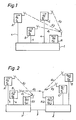
- the method is described with reference to FIG. 2 if the transmitters are divided into several groups, each group having a transmitter control device with a receiver.
- 2 shows two groups of transmitters, the first group with the transmitters A and B and the transmitter control device 1 with the receiver R1 and the second group with the transmitters C and D and the transmitter control device 2 with the receiver R2.
- the method with two groups presupposes that at least one transmitter in one group has a radio connection with the receiver in the other group. In the example shown, it is assumed that this radio connection exists between the transmitter B of the first group and the receiver R2 of the second group.
- there is a communication connection between the two transmitter control devices either via a simple line connection 3 or via a control device common to the transmitter control devices (network control unit 15 3) for the radio network.
- the synchronization is carried out as follows:
- the two groups are each individually synchronized according to the inventive method, as has been explained in connection with FIG. 1.
- the new times are accordingly
- transmitter B sends a synchronization message, which shows the current time (actual time) T B. from transmitter B contains.
- the receiver R2 registers the time T R2 at which it receives this synchronization message.
- T R2 T B , + d B + d5 + T B - T R2 (11)
- T B - T R2 represents the unknown time difference between the clock of transmitter B and the clock of receiver R2.
- the control device 2 then divides the value T R2 . to the control device 1 of the first group and thus to the transmitters A and B.
- the correction value K2 can also be used to correct the clock in transmitter A (or to correct all other transmitters group 1). It should be noted, however, that in this case of group synchronization, only the signal delay value (d B ) of the one transmitter (B) sending the synchronization message is included in the correction value. The other transmitters in the first group will not run exactly in sync.
- the new times for Group 1 channels are:
- the synchronization condition is therefore exactly fulfilled for transmitters B, C and D.
- the remaining error (d A - d B ) at transmitter A is only minor, since it consists of the difference between small signal delays of a similar magnitude. Furthermore, these signal propagation times are generally known, and the difference could therefore also be compensated for.
- T B ' which is primarily only known in the transmitter B.
- Fig. 3 shows the block diagram of a paging system in which the method is preferably applied.
- the paging system essentially consists of a paging terminal 14 connected to the public telephone network 13 and the paging network.
- the paging network is composed of a network control unit 15, a plurality of transmitter group controllers 16 connected thereto and a plurality of transmitter stations 17.
- the transmitter stations 17 are combined in groups and each connected to the transmitter group control device 16 of this group.
- the transmitter stations are in turn divided into an interface (TSI) and the actual transmitter.
- TSI interface
- the paging center forms the interface to the public telephone network. It manages the subscriber data and converts the incoming calls into serial data streams (e.g. in the aforementioned POCSAG format).
- the network is structured hierarchically.
- the individual units are connected to each other via modem lines, on which they communicate with one another in purely digital form. Commands, messages about the system status and, if necessary, alarm messages are exchanged.
- All call reports are buffered both in the network control unit and in the transmitter group control devices 16 and TSI, and there is no direct connection between a call report arrival time in the transmitter station and the time it was broadcast by the transmitter.
- the call message contains the code information for the call receivers, not shown, who are in the area of the paging network.
- the transmitter group control device is additionally provided with a receiver which operates on the frequency of the transmitters.
- the transmitters additionally have a circuit for determining the correction value and correspondingly adapting their - already existing - clock. This circuit is usually implemented by the transmitter's microprocessor control.
- Fig. 4 shows a block diagram of a transmitter group control device.
- the controlling microprocessor 6, storage means 7, an initialization and monitoring circuit 8 and - via an interface 9 - the receiver 10 are connected to their connecting bus 5.
- serial interfaces 11 and modems 12 are provided, by means of which the control device is connected via telephone lines to the transmitters 17 on the one hand and to the network control unit 15 on the other hand.
Abstract
Description
Die Erfindung betrifft ein Verfahren zur Synchronisation mehrerer Sender, welche mit einer mit einer Uhr versehenen Steuereinrichtung verbunden sind, wobei jeder Sender in bekanntem Abstand von der Steuereinrichtung angeordnet ist und eine zu synchronisierende Uhr aufweist.The invention relates to a method for synchronizing a plurality of transmitters which are connected to a control device provided with a clock, each transmitter being arranged at a known distance from the control device and having a clock to be synchronized.
Ferner betrifft die Erfindung eine Sendersteuereinrichtung und einen Sender zur Durchführung des Verfahrens und betrifft eine Anwendung des Verfahrens bei einem Funkrufnetz.The invention further relates to a transmitter control device and a transmitter for performing the method and relates to an application of the method to a radio paging network.
Bei einem Einsatz mehrerer Funksender, welche ein Gebiet flächendecken mit dem gleichen Signal versorgen, kann sich das Problem der Synchronisation der Sender ergeben, dies z.B. bei einem Ortsrufnetz, bei dem digitale Erkennungskodes für die einzelnen Rufempfänger gesendet werden.If several radio transmitters are used, which supply an area with the same signal, the problem of synchronization of the transmitters can arise, for example in the case of a local network, in which digital identification codes are sent for the individual call receivers.
Die Synchronisation, von der hier die Rede ist, bezieht sich dabei auf die Modulation der Sender, nicht auf deren HF-Träger. Die HF-Träger werden frei laufengelassen und wenn nötig, mit einem gewissen Frequenzversatz betrieben, damit sich keine stehenden Wellen ausbilden, die zu "Löchern" im Versorgungsgebiet führen.The synchronization, of which we are talking here, relates to the modulation of the transmitters, not to their HF carriers. The RF carriers are allowed to run freely and, if necessary, are operated with a certain frequency offset so that no standing waves are formed which lead to "holes" in the coverage area.
Solange z.B. ein Rufempfänger (Pager) nur von einem Sender Signale empfängt, stellt sich das Synchronisationsproblem nicht. Sobald er sich jedoch im gemeinsamen Versorgungsgebiet zweier oder mehrerer Sender befindet, die nicht synchron arbeiten, wird er grosse Probleme haben, die empfangenen Signale richtig zu detektieren. In den meisten Fällen ist es ja aus Gründen der Versorungssicherheit sehr erwünscht, dass sich die Versorgungsgebiete der einzelnen Sender überlappen.As long as a pager receives signals from only one transmitter, the synchronization problem does not arise. However, as soon as it is in the common coverage area of two or more transmitters that are not working synchronously, it will have great problems in correctly detecting the signals received. In most cases, for reasons of security of supply, it is very desirable that the coverage areas of the individual transmitters overlap.
Es gibt natürlich auch Möglichkeiten, ohne Synchronisation auszukommen, jedoch haben alle diese Varianten grosse Nachteile, vor allem bezüglich Frequenz- und Zeitökonomie.Of course, there are also ways to get by without synchronization, but all of these variants have major disadvantages, especially with regard to frequency and time economy.
Bei bekannten Funkeinrichtungen mit mehreren Sendern sind diese über Modulationsleitungen direkt mit der Signalquelle, z.B. mit der Rufzentrale eines Funkrufnetzes, verbunden. Die Leitungen werden mit Laufzeitreglern versehen, die eine gewisse Kompensation der unterschiedlichen Distanzen zwischen Rufzentrale und Sendern ermöglichen.In known radio devices with several transmitters, these are connected directly to the signal source, e.g. connected to the call center of a paging network. The lines are provided with transit time controllers, which allow a certain compensation of the different distances between call center and transmitters.
Abgeglichen wird vielfach aber nur die Strecke bis zum Sendereingang. Für die Synchronisation sind jedoch die Signale an den Antennen massgebend, so dass die unterschiedlichen Laufzeiten in den Sendern nicht berücksichtigt werden.In many cases, however, only the route to the transmitter entrance is compared. However, the signals on the antennas are decisive for the synchronization, so that the different transit times in the transmitters are not taken into account.
Ein wesentlicher Nachteil des Verfahrens ist, dass die Eigenschaften der Modulationsleitungen und der beteiligten Geräte infolge von Witterungseinflüssen, Temperatur und Alterung laufend verändern. Es ergibt sich daraus ein relativ grosser Aufwand für das periodische Justieren der Anlage.A major disadvantage of the method is that the properties of the modulation lines and the devices involved continuously change due to weather influences, temperature and aging. This results in a relatively large effort for the periodic adjustment of the system.
Fällt eine Leitung aus, muss die Ersatzleitung in jedem Fall neu eingeregelt werden.If a line fails, the replacement line must be readjusted in any case.
Der Erfindung liegt deshalb die Aufgabe zugrunde, ein Verfahren der eingangs genannten Art zu schaffen, welches die genannten Nachteile nicht aufweist und eine einfache und schnelle Sendersynchronisation erlaubt. Dies wird dadurch erreicht, dass zur Synchronisation der Senderuhren von jedem Sender eine Istuhrzeitmeldung ausgestrahlt wird, die von der Steuereinrichtung mittels eines Funkempfängers empfangen wird und deren Empfangsuhrzeit in der Steuereinrichtung bestimmt und von dieser an den Sender übermittelt wird und dass in jedem Sender Istuhrzeitmeldung, Empfangsurzeit, Sendesignallaufzeit zwischen Sender und Empfänger sowie die momentane Senderuhrzeit verknüpft werden, um die synchronisierte Senderuhrzeit zu erhalten. Ferner stellt sich die Aufgabe, eine Sendesteuereinrichtung und einen Sender zur Durchführung des Verfahrens zu schaffen. Dies wird durch eine Sendersteuereinrichtung mit den kennzeichnenden Merkmalen des Patentanspruches 4 erreicht, bzw. durch einen Sender mit den kennzeichnenden Merkmalen des Patentanspruches 5.The invention is therefore based on the object of providing a method of the type mentioned at the outset which does not have the disadvantages mentioned and which permits simple and fast transmitter synchronization. This is achieved in that, for the synchronization of the transmitter clocks, an actual time message is emitted by each transmitter, which is received by the control device by means of a radio receiver and whose reception time is determined in the control device and transmitted by the latter to the transmitter, and that in each transmitter the actual time message, time of receipt , Transmission signal transit time between transmitter and receiver and the current transmitter time can be linked in order to obtain the synchronized transmitter time. Furthermore, there is the task of creating a transmission control device and a transmitter for performing the method. This is achieved by a transmitter control device with the characterizing features of
Ferner wird eine Anwendung des Verfahrens gemäss Patentanspruch 7 gezeigt.Furthermore, an application of the method according to
Bei einer bevorzugten Anwendung werden zwei Gruppen von Sendern zunächst intern und nachfolgend miteinander synchronisiert.In a preferred application, two groups of transmitters are first synchronized internally and subsequently with one another.
Nachfolgend werden Ausführungsbeispiele anhand der Zeichnungen näher erläutert. Dabei zeigt:
- Fig. 1 schematisch eine Anordnung von drei zu synchronisierenden Sendern und der Steuereinrichtung;
- Fig. 2 schematisch zwei Gruppen von zu synchronisierenden Sendern mit zugehörigen Sendesteuereinrichtungen;
- Fig. 3 ein Blockschaltbild einer Funkrufanlage;
- Fig. 4 ein Blockschaltbild einer Sendesteuereinrichtung.
- 1 schematically shows an arrangement of three transmitters to be synchronized and the control device;
- 2 shows schematically two groups of transmitters to be synchronized with associated transmission control devices;
- Fig. 3 is a block diagram of a radio paging system;
- Fig. 4 is a block diagram of a transmission control device.
Damit ein im überlappenden Sendegebiet mehrerer Sender befindlicher Empfänger dieselbe, von allen Sendern ausgesandte Nachricht eindeutig identifizieren kann, muss die Nachricht von allen Sendern zur selben Zeit abgestrahlt werden. Zur selben Zeit abgestrahlt bedeutet dabei, dass die Abstrahlzeitpunkte des Nachrichtensignals von den Sendeantennen eine vorausbestimmte Zeitdifferenz nicht überschreiten. So sind bei Funkrufnetzen, in welchen als Nachrichten Digitalsignale für die Rufempfänger ausgestrahlt werden, die Meldungsprotokolle (z.B. im postalisch spezifizierten POCSAG-Format) und die geforderte Zeitdifferenz, bzw. die Synchronisationsgenauigkeit bestimmt. Diese beträgt z.B. 1/4 Bit, was bei 512 Bit/s einer Zeitdifferenz von 488 µs entspricht.So that a receiver located in the overlapping transmission area of several transmitters can clearly identify the same message sent by all transmitters, the message must be emitted by all transmitters at the same time. Radiated at the same time means that the emission times of the message signal from the transmitting antennas do not exceed a predetermined time difference. In the case of paging networks in which digital signals are broadcast for the call recipients, the message protocols (e.g. in the POCSAG format specified by post) and the required time difference or the synchronization accuracy are determined. This is e.g. 1/4 bit, which corresponds to a time difference of 488 µs at 512 bit / s.
Jede auszusendende Nachricht wird bei solchen Funkrufnezten mit einer Sollsendezeit versehen, und sobald die interne Uhr jedes Senders diese Zeit erreicht hat, wird diese Nachricht gesendet. Es ist daher nötig, die Senderuhren zu synchronisieren, damit die geforderte Genauigkeit erreicht werden kann. Ferner ist zu beachten, dass die Sendersignalverzögerungszeit für jeden Sender unterschiedlich (aber bekannt) ist. Da die Uhren (Taktoszillatoren) der Sender verschiedene Genauigkeit und unterschiedlichen Drift aufweisen, muss die Synchronisation von Zeit zu Zeit wiederholt werden.In such paging networks, each message to be sent is provided with a target transmission time, and as soon as the internal clock of each transmitter has reached this time, this message is sent. It is therefore necessary synchronize the transmitter clocks so that the required accuracy can be achieved. It should also be noted that the transmitter signal delay time is different (but known) for each transmitter. Since the clocks (clock oscillators) of the transmitters have different accuracy and different drift, the synchronization must be repeated from time to time.
Das erfindungsgemässe Verfahren soll nun anhand der Senderkonfiguration von Fig. 1 erklärt werden. Dabei sind mit A, B und C drei Funksender bezeichnet. Die Sender sind mit einer Sendesteuereinrichtung 1 leitungsverbunden, welche über die Leitungen 4 Steuerbefehle und auszusendende Nachrichten an die Sender schickt. Dabei bedeuten:

Das Ziel der Synchronisation ist es, dass gleiche Modulationssignale jeweils zur genau gleichen Zeit von den Antennen der beiden Sender abgestrahlt werden.The aim of the synchronization is that the same modulation signals are always the same Time from the antennas of the two transmitters.
Die Synchronisationsbedingung lautet als:
TA + dA = TB + dB = TC + dC
The synchronization condition is as:
T A + d A = T B + d B = T C + d C
Die eigentliche Synchronisation wird nun wie folgt durchgeführt. Zunächst übermittelt die Steuereinrichtung 1 einen Befehl an die Sender, durch welchen diese veranlasst werden, ihre Senderuhrzeit auf eine Zeit vor der Empfänger- bzw. Steuereinrichtungsuhrzeit zu stellen; es gilt daher
TA< TR; TB < TR; TC < TR (1)
The actual synchronization is now carried out as follows. First of all, the control device 1 transmits a command to the transmitters, by means of which they are caused to set their transmitter time to a time before the receiver or control device time; therefore it applies
T A <T R ; T B <T R ; T C <T R (1)
Danach werden die Sender von der Sendesteuereinrichtung (in beliebiger Reihenfolge) veranlasst, eine Synchronisationsmeldung abzustrahlen, welche ihre lokale Uhrzeit (Istuhrzeit) enthält. Zum Beispiel strahlt der Sender A eine Synchronisationsmeldung ab, welche seine Istuhrzeit TA, enthält.The transmitters are then prompted by the transmission control device (in any order) to emit a synchronization message which contains their local time (actual time). For example, the transmitter A emits a synchronization message which contains its actual time T A.
Der Empfänger R registriert seine Uhrzeit TR, Empfangsuhrzeit), zu welcher er die Synchronisationsmeldung des Senders A empfangen hat. Dabei gilt
TR, = TA, + dA + d₁ + dR + TA - TR (2)
The receiver R registers its time T R (reception time) at which it received the synchronization message from the transmitter A. The following applies
T R , = T A , + d A + d₁ + d R + T A - T R (2)
Bei dem Term TA - TR handelt es sich dabei um die unbekannte Zeitdifferenz der Uhren von Sender A und Empfänger R.The term T A - T R is the unknown time difference between the clocks of transmitter A and receiver R.
Ueber die Leitungsverbindung 4 übermittelt die Steuereinrichtung den Wert TR, an den Sender A.The control device transmits the value T R to the transmitter A via the
Der Sender A bildet einen Korrekturwert für seine Uhr aus dem übermittelten Wert TR, und den ihm bekannten Werten TA, und d₁ auf folgende Weise:
K = TR, - TA, - d₁ (3)
The transmitter A forms a correction value for its watch from the transmitted value T R , and the values T A known to it , and d 1 in the following way:
K = T R , - T A , - d₁ (3)
Ein Vergleich mit Formel (2) zeigt, dass gilt
K = TR, - TA, - d₁ = TA - TR + dA + dR (4)
Der Korrekturwert K wird nun vom Sender von seiner jetzigen Uhrzeit TA subtrahiert, um die neue, synchronisierte Uhrzeit TAS zu bilden. Dabei gilt mit (4)
TAS = TA-K = TA-TA+TR-dA-dR = TR-dA-dR (5)
A comparison with formula (2) shows that the following applies
K = T R , - T A , - d₁ = T A - T R + d A + d R (4)
The correction value K is now subtracted from the current time T A by the transmitter in order to form the new, synchronized time T AS . The following applies with (4)
T AS = T A -K = T A -T A + T R -d A -d R = T R -d A -d R (5)
Das heisst, die neue Zeit TAS ist von der alten Sendeuhrzeit TA unabhängig.This means that the new time T AS is independent of the old transmission time T A.
Die Uhren der übrigen Sender B und C werden mit den gleichen Schritten korrigiert (in den Formeln sind lediglich die Indizes A durch B bzw. C zu ersetzen).The clocks of the other transmitters B and C are corrected with the same steps (in the formulas only the indices A are replaced by B and C, respectively).
Die neuen Zeiten sind demnach:
Mit jedem Paket von Nutzinformation erhalten die Sender eine Zeitangabe T, die den Sendezeitpunkt bestimmt.With each packet of useful information, the transmitters receive a time specification T, which determines the time of transmission.
Die Zeiten, zu denen die Nutzinformation an den Antennen ercheint, sind
TAS + dA = TBS + dB = TCS + dC
The times when the payload appears on the antennas are
T AS + d A = T BS + d B = T CS + d C
Die Synchronisationsbedingung ist damit für die neuen Uhrzeiten erfüllt.The synchronization condition is thus fulfilled for the new times.
Der Synchronisationsvorgang spielt sich auch für eine grössere Anzahl von Sendern gleich ab. Ebenfalls ist es unerheblich, ob der ganze Vorgang zunächst für den Sender A erfolgt und Sender B nachfolgend seine Synchronisationsmeldung sendet oder ob zunächst alle Sender A,B,C nacheinander ihre Synchronisationsmeldungen senden und nachfolgend nacheinander oder gleichzeitig die jeweiligen Zeiten TR, an die Sender übermittelt werden.The synchronization process also takes place for a large number of transmitters. It is also irrelevant whether the whole process takes place first for transmitter A and transmitter B subsequently sends its synchronization message or whether all transmitters A, B, C first send their synchronization messages in succession and subsequently in succession or simultaneously the respective times T R to the transmitters be transmitted.
Mit Bezug auf Fig. 2 soll das Verfahren geschildert werden, wenn die Sender in mehrere Gruppen eingeteilt sind, wobei jede Gruppe eine Sendersteuereinrichtung mit Empfänger aufweist. In Fig. 2 sind zwei Gruppen von Sendern dargestellt, die erste Gruppe mit den sendern A und B und der Sendersteuereinrichtung 1 mit dem Empfänger R1 und die zweite Gruppe mit den Sendern C und D sowie der Sendersteuereinrichtung 2 mit dem Empfänger R2. Zusätzlich zu den bereits im Zusammenhang mit Fig. 1 geschilderten Voraussetzungen ist bei dem Verfahren mit zwei Gruppen vorausgesetzt, dass mindestens ein Sender der einen Gruppe Funkverbindung mit dem Empfänger der anderen Gruppe hat. Im gezeigten Beispiel ist angenommen, diese Funkverbindung bestehe zwischen dem Sender B der ersten Gruppe und dem Empfänger R2 der zweiten Gruppe, Ferner besteht eine Kommunikationsverbindung zwischen den beiden Sendersteuereinrichtungen, sei es über eine einfache Leitungsverbindung 3 oder über eine den Sendersteuereinrichtungen gemeinsame Steuervorrichtung (Netzsteuereinheit 15; Fig. 3) für das Funknetz.The method is described with reference to FIG. 2 if the transmitters are divided into several groups, each group having a transmitter control device with a receiver. 2 shows two groups of transmitters, the first group with the transmitters A and B and the transmitter control device 1 with the receiver R1 and the second group with the transmitters C and D and the
Die Synchronisationsbedingung für das vorliegende Beispiel lautet:
TA + dA = TB + dB = TC + dC = TD + dD (8)
The synchronization condition for this example is:
T A + d A = T B + d B = T C + d C = T D + d D (8)
Die Synchronisation wird wie folgt durchgeführt:The synchronization is carried out as follows:
Zunächst werden die beiden Gruppen jede für sich gemäss dem erfindungsgemässen Verfahren synchronisiert, wie dies im Zusammenhang mit Fig. 1 erläutet worden ist. Die neuen Zeiten sind demnach

Danach wird die eine Gruppe erneut nach dem Verfahren synchronisiert, diesmal mit Hilfe des Empfängers der anderen Gruppe. Anhand des Beispiels von Fig. 2 im einzelnen:Then the one group is synchronized again according to the method, this time with the help of the recipient of the other group. Using the example of FIG. 2 in detail:
Alle Uhren der Gruppe 1 werden um den gleichen konstanten Betrag zurückgestellt, so dass sie eine frühere Zeit als die Empfängeruhr vom Empfänger R2 erhalten:
TA = TB; TB < TR2 (10)
All group 1 clocks are reset by the same constant amount so that they receive an earlier time than the receiver clock from the receiver R2:
T A = T B ; T B <T R2 (10)
Danach sendet Sender B eine Synchronisationsmeldung, welche die aktuelle Zeit (Ist-Uhrzeit) TB. von Sender B enthält.Thereafter, transmitter B sends a synchronization message, which shows the current time (actual time) T B. from transmitter B contains.
Der Empfänger R2 registriert den Zeitpunkt TR2,zu dem er diese Synchronisationsmeldung empfängt. Es gilt:
TR2, = TB, + dB + d₅ + TB - TR2 (11)
The receiver R2 registers the time T R2 at which it receives this synchronization message. The following applies:
T R2 , = T B , + d B + d₅ + T B - T R2 (11)
Der Term TB - TR2 stellt die unbekannte Zeitdifferenz zwischen der Uhr des Senders B und der Uhr des Empfängers R2 dar.The term T B - T R2 represents the unknown time difference between the clock of transmitter B and the clock of receiver R2.
Danach teilt die Steuereinrichtung 2 den Wert TR2. an die Steuereinrichtung 1 der ersten Gruppe und damit an die Sender A und B mit.The
Alle Sender der ersten Gruppe korrigieren ihre Uhr mittels des Korrekturwertes K2, welcher wie folgt gebildet ist:
K2 = TR2′ - TB. - d₅ (12)
All transmitters in the first group correct their clock using the correction value K2, which is formed as follows:
K2 = T R2 ′ - T B. - d₅ (12)
Im Vergleich mit (11) ergibt sich
K2 = TB - TR2 + dB dR2 (13)
In comparison with (11) it follows
K2 = T B - T R2 + d B d R2 (13)
Da von der ersten Synchronisation der ersten Gruppe her weiterhin TA = TB gilt, kann der Korrekturwert K2 auch zur Korrektur der Uhr im Sender A verwendet werden (bzw. zur Korrektur aller weiteren Sender Gruppe 1). Dabei ist aber zu beachten, dass in diesem Fall der Gruppensynchronisation immer nur der Signalverzögerungswert (dB) des einen die Synchronisationsmeldung sendenden Senders (B) in den Korrekturwert eingeht. Die weiteren Sender der ersten Gruppe werden also nicht genau synchron laufen.Since T A = T B still applies from the first synchronization of the first group, the correction value K2 can also be used to correct the clock in transmitter A (or to correct all other transmitters group 1). It should be noted, however, that in this case of group synchronization, only the signal delay value (d B ) of the one transmitter (B) sending the synchronization message is included in the correction value. The other transmitters in the first group will not run exactly in sync.
Die neuen Zeiten der Sender von Gruppe 1 sind demnach:
Die Zeiten, zu denen die Nutzinformation an den Antennen erscheinen, sind demzufolge:
Die Synchronisationsbedingung ist also für die Sender B,C und D exakt erfüllt. Der bleibende Fehler (dA - dB) bei Sender A ist nur geringfügig, da er aus der Differenz kleiner Signallaufzeiten ähnlicher Grössenordnung besteht. Ferner sind diese Signallaufzeiten grundsätzlich bekannt, und die Differenz könnte deshalb auch kompenseirt werden.The synchronization condition is therefore exactly fulfilled for transmitters B, C and D. The remaining error (d A - d B ) at transmitter A is only minor, since it consists of the difference between small signal delays of a similar magnitude. Furthermore, these signal propagation times are generally known, and the difference could therefore also be compensated for.
Zu der Ermittlung des Korrekturwertes K2 bleibt zu bemerken, dass dieser mittels des Wertes TB′ ermittelt wird, welcher primär nur im Sender B bekannt ist. Für die anderen Sender (A) kann auf verschiedene Weise vorgegangen werden: Erfolgt der Sendebefehl für die Synchronisationsmeldung von Sender B in vorausbestimmten Abstand von einem festen Zeitwert der Uhr in B, so können die anderen Sender mittels des Sendebnefehls aus der Steuereinrichtung der Zeit TB′ erkennen (da TA = TB). Andernfalls kann entwerder TB′ oder K2 vom Sender B über die Steuereinrichtung an die anderen Sender der gleichen Gruppe (Sender A) übermittelt werden.Regarding the determination of the correction value K2, it should be noted that this is determined by means of the value T B ', which is primarily only known in the transmitter B. The other transmitters (A) can be operated in different ways: If the transmit command for the synchronization message from transmitter B is given at a predetermined distance from a fixed time value of the clock in B, the other transmitters can use the transmit transmit command from the control device of time T B 'Recognize (since T A = T B ). Otherwise, either T B 'or K2 can be transmitted from transmitter B via the control device to the other transmitters in the same group (transmitter A).
Bestehen mehr als zwei Gruppen, so wird auf gleiche Weise vorgegangen, indem immer zwei Gruppen miteinander synchronisiert werden und diese eine neue Gruppe bildet, welche dann erneut mit einer zweiten Gruppe synchronisiert wird, usw.If there are more than two groups, the same procedure is followed in that two groups are always synchronized with each other and this forms a new group, which is then synchronized again with a second group, etc.
Fig. 3 zeigt das Blockschaltbild eines Funkrufsystems, bei dem das Verfahren vorzugsweise angewendet wird. Das Funkrufsystem besteht im wesentlichen aus einer mit dem öffentlichen Telefonnetz 13 verbundenen Funkrufzentrale 14 (paging terminal) sowie dem Rufnetzwerk. Das Rufnetzwerk (paging network) setzt sich aus einer Netzsteuereinheit 15 (paging network unit), mehreren damit verbundenen Sendergruppensteuereinrichtungen 16 (transmitter group controllers) and einer Mehrzahl von Sendestationen 17 zusammen. Die Sendestationen 17 sind in Gruppen zusammengefasst und jeweils mit der Sendergruppensteuereinrichtung 16 dieser Gruppe verbunden. Die Sendestationen wiederum sind in eine Schnittstelle (TSI) und den eigentlichen Sender unterteilt.Fig. 3 shows the block diagram of a paging system in which the method is preferably applied. The paging system essentially consists of a
Die Funkrufzentrale bildet die Schnittstelle zum öffentlichen Telefonnetz. Sie verwaltet die Teilnehmerdaten und setzt die ankommenden Anrufe in serielle Datenströme (z.B. ins erwähnte POCSAG-Format) um.The paging center forms the interface to the public telephone network. It manages the subscriber data and converts the incoming calls into serial data streams (e.g. in the aforementioned POCSAG format).
Das Netzwerk ist hierarchisch aufgebaut. Die einzelnen Einheiten sind über Modemleitungen miteinander verbunden, auf denen sie in rein digitaler Form miteinander kommunizieren. Es werden dauernd Befehle, Meldungen über den Systemzustand und wenn nötig Alarmmeldungen ausgetauscht.The network is structured hierarchically. The individual units are connected to each other via modem lines, on which they communicate with one another in purely digital form. Commands, messages about the system status and, if necessary, alarm messages are exchanged.
Alle Rufmeldungen werden sowohl in der Netzsteuereinheit als auch in den Sendergruppensteuereinrichtungen 16 und TSI zwischengespeichert, und es gibt für eine Rufmeldung keinen direkten Zusammenhang zwischen ihrer Ankunftszeit in der Sendestation und der Zeit ihrer Ausstrahlung durch den Sender.All call reports are buffered both in the network control unit and in the transmitter
Hingegen wird durch die Synchronisation garantiert, dass eine bestimmte Rufmeldung von allen Sendern zur gleichen Zeit ausgestrahlt wird.On the other hand, synchronization guarantees that a specific call message is broadcast by all transmitters at the same time.
Die Rufmeldung enthält die Kodeinformation für die nicht dargestellten Rufempfänger, die sich im Bereich des Funkrufnetzes aufhalten.The call message contains the code information for the call receivers, not shown, who are in the area of the paging network.
Die genannten Elemente des Funkrufsystems sind handelsüblich und bekannt. Die Sendergruppensteuereinrichtung ist zur Durchführung des Verfahrens zusätzlich mit einem Empfänger versehen, welcher auf der Frequenz der Sender arbeitet. Die Sender weisen zusätzlich eine Schaltung zur Ermittlung des Korrekturwertes und entsprechender Anpassung ihrer - bereits vorhandenen - Uhr auf. Diese Schaltung wird in der Regel durch die Mikroprozessorsteuerung des Senders implementiert.The elements of the paging system mentioned are commercially available and known. To carry out the method, the transmitter group control device is additionally provided with a receiver which operates on the frequency of the transmitters. The transmitters additionally have a circuit for determining the correction value and correspondingly adapting their - already existing - clock. This circuit is usually implemented by the transmitter's microprocessor control.
Fig. 4 zeigt ein Blockschaltbild einer Sendergruppensteuereinrichtung. An deren Verbindungsbus 5 sind der steuernde Mikroprozessor 6, Speichermittel 7, eine Initialisierungs- und Ueberwachungsschaltung 8 und - über eine Schnittstelle 9 - der Empfänger 10 angeschlossen. Ferner sind serielle Schnittstellen 11 und Modems 12 vorgesehen, mittels denen die Steuereinrichtung über Telefonleitungen mit den Sendern 17 einerseits und der Netzsteuereinheit 15 andererseits in Verbindung steht.Fig. 4 shows a block diagram of a transmitter group control device. The controlling
Claims (9)
Applications Claiming Priority (2)
| Application Number | Priority Date | Filing Date | Title |
|---|---|---|---|
| CH4250/87 | 1987-10-28 | ||
| CH425087A CH670545GA3 (en) | 1987-10-28 | 1987-10-28 |
Publications (2)
| Publication Number | Publication Date |
|---|---|
| EP0315028A1 true EP0315028A1 (en) | 1989-05-10 |
| EP0315028B1 EP0315028B1 (en) | 1991-11-21 |
Family
ID=4272603
Family Applications (1)
| Application Number | Title | Priority Date | Filing Date |
|---|---|---|---|
| EP88117745A Expired - Lifetime EP0315028B1 (en) | 1987-10-28 | 1988-10-25 | Method for synchronising transmitters, control means and transmitters using said method and the application of said method |
Country Status (5)
| Country | Link |
|---|---|
| EP (1) | EP0315028B1 (en) |
| AT (1) | ATE69657T1 (en) |
| CH (1) | CH670545GA3 (en) |
| DE (1) | DE3866334D1 (en) |
| ES (1) | ES2027364T3 (en) |
Cited By (3)
| Publication number | Priority date | Publication date | Assignee | Title |
|---|---|---|---|---|
| EP0702464A1 (en) * | 1994-09-14 | 1996-03-20 | Racotek, Inc. | Data communication system with time synchronization |
| WO1996017278A1 (en) * | 1994-11-29 | 1996-06-06 | Gpt Limited | Clock synchronisation |
| WO1998014842A1 (en) * | 1996-10-03 | 1998-04-09 | H.P.M. Technologies Pty. Ltd. | Synchronization of a timepiece to a reference time |
Families Citing this family (1)
| Publication number | Priority date | Publication date | Assignee | Title |
|---|---|---|---|---|
| US7286624B2 (en) * | 2003-07-03 | 2007-10-23 | Navcom Technology Inc. | Two-way RF ranging system and method for local positioning |
Citations (4)
| Publication number | Priority date | Publication date | Assignee | Title |
|---|---|---|---|---|
| EP0084165A1 (en) * | 1981-12-25 | 1983-07-27 | Nec Corporation | Remote calibrating system for satellite time |
| CA1158739A (en) * | 1980-04-30 | 1983-12-13 | William Rodman | Distributed network synchronization system |
| FR2564668A1 (en) * | 1984-05-15 | 1985-11-22 | Thomson Csf | Decentralised and synchronous method of transmitting information, and information transmission network using this method |
| EP0253096A2 (en) * | 1986-05-20 | 1988-01-20 | Mitsubishi Denki Kabushiki Kaisha | Time synchronization method in a data transmission system |
-
1987
- 1987-10-28 CH CH425087A patent/CH670545GA3/de not_active IP Right Cessation
-
1988
- 1988-10-25 EP EP88117745A patent/EP0315028B1/en not_active Expired - Lifetime
- 1988-10-25 AT AT88117745T patent/ATE69657T1/en not_active IP Right Cessation
- 1988-10-25 ES ES198888117745T patent/ES2027364T3/en not_active Expired - Lifetime
- 1988-10-25 DE DE8888117745T patent/DE3866334D1/en not_active Expired - Fee Related
Patent Citations (4)
| Publication number | Priority date | Publication date | Assignee | Title |
|---|---|---|---|---|
| CA1158739A (en) * | 1980-04-30 | 1983-12-13 | William Rodman | Distributed network synchronization system |
| EP0084165A1 (en) * | 1981-12-25 | 1983-07-27 | Nec Corporation | Remote calibrating system for satellite time |
| FR2564668A1 (en) * | 1984-05-15 | 1985-11-22 | Thomson Csf | Decentralised and synchronous method of transmitting information, and information transmission network using this method |
| EP0253096A2 (en) * | 1986-05-20 | 1988-01-20 | Mitsubishi Denki Kabushiki Kaisha | Time synchronization method in a data transmission system |
Cited By (4)
| Publication number | Priority date | Publication date | Assignee | Title |
|---|---|---|---|---|
| EP0702464A1 (en) * | 1994-09-14 | 1996-03-20 | Racotek, Inc. | Data communication system with time synchronization |
| WO1996017278A1 (en) * | 1994-11-29 | 1996-06-06 | Gpt Limited | Clock synchronisation |
| US6009530A (en) * | 1994-11-29 | 1999-12-28 | Gpt Limited | Real time clock synchronization in a telecommunications network |
| WO1998014842A1 (en) * | 1996-10-03 | 1998-04-09 | H.P.M. Technologies Pty. Ltd. | Synchronization of a timepiece to a reference time |
Also Published As
| Publication number | Publication date |
|---|---|
| ATE69657T1 (en) | 1991-12-15 |
| EP0315028B1 (en) | 1991-11-21 |
| DE3866334D1 (en) | 1992-01-02 |
| CH670545GA3 (en) | 1989-06-30 |
| ES2027364T3 (en) | 1992-06-01 |
Similar Documents
| Publication | Publication Date | Title |
|---|---|---|
| DE60030363T2 (en) | Radio network controller | |
| DE60103758T2 (en) | MASTER / SLAVE SYNCHRONIZATION PROCEDURE IN A BLUETOOTH SYSTEM | |
| DE2733503C3 (en) | Mobile communication radio system | |
| DE69936753T2 (en) | METHOD FOR OPERATIONAL MONITORING OF A CELLULAR RADIO SYSTEM | |
| DE2523996C3 (en) | Radiotelephony system | |
| DE2615198A1 (en) | MESSAGE TRANSMISSION SYSTEM FOR TWO-SIDED MESSAGE TRAFFIC BETWEEN A MAIN STATION AND SEVERAL SUBSTATIONS VIA A SATELLITE | |
| DE2050718B2 (en) | Method for communication via an earth satellite by means of time division multiplex and device for carrying out the method | |
| DE69934656T2 (en) | Wireless access method in which the control information is transmitted several times and in advance. | |
| EP1251646B1 (en) | Method for halfduplex transmission of informations between communication devices with repeaters | |
| EP1198911B1 (en) | Synchronisation method and system for clock signal sources, in particular in packet transmission communication systems | |
| EP0198448A1 (en) | Method for the synchronization of several pulsed transmitters-receivers | |
| EP0020893B1 (en) | Radio network | |
| EP0315028B1 (en) | Method for synchronising transmitters, control means and transmitters using said method and the application of said method | |
| DE2339392C3 (en) | Method for calling up outstations by a central station and CIRCUIT ARRANGEMENT FOR carrying out this method | |
| DE69926489T2 (en) | DATA TRANSMISSION PROCEDURE AND SYSTEM | |
| EP0118710B1 (en) | Synchronizing device for the useful signals of a common frequency broadcasting system | |
| EP0326630B1 (en) | Method for transmitting remote control signals on a single carrier frequency between autonomous transmitters and receivers in time multiplexe and arrangement for realization of this method | |
| EP0448927A1 (en) | Procedure for the transmission of time discrete information | |
| DE69637421T2 (en) | Method for a data bus system with resource control and transmission station resources | |
| EP0536539B1 (en) | Paging network for transmission of subscriber related paging signals and method for use | |
| DE2410380A1 (en) | LOCATION SYSTEM WITH MORE THAN TWO LOCATION DEVICES | |
| DE19701175B4 (en) | Method of signaling | |
| EP0111164A1 (en) | Radio system | |
| EP0086865A2 (en) | Method of wireless transmission of digital information by means of one transmission frequency | |
| DE10110177B4 (en) | A method of measuring and compensating for the propagation delay between nodes in a communication network |
Legal Events
| Date | Code | Title | Description |
|---|---|---|---|
| PUAI | Public reference made under article 153(3) epc to a published international application that has entered the european phase |
Free format text: ORIGINAL CODE: 0009012 |
|
| AK | Designated contracting states |
Kind code of ref document: A1 Designated state(s): AT BE DE ES FR GB GR IT LU NL SE |
|
| 17P | Request for examination filed |
Effective date: 19891102 |
|
| 17Q | First examination report despatched |
Effective date: 19901102 |
|
| RAP1 | Party data changed (applicant data changed or rights of an application transferred) |
Owner name: FIRMA ERIKA KOECHLER |
|
| GRAA | (expected) grant |
Free format text: ORIGINAL CODE: 0009210 |
|
| AK | Designated contracting states |
Kind code of ref document: B1 Designated state(s): AT BE DE ES FR GB GR IT LU NL SE |
|
| PG25 | Lapsed in a contracting state [announced via postgrant information from national office to epo] |
Ref country code: GR Free format text: LAPSE BECAUSE OF FAILURE TO SUBMIT A TRANSLATION OF THE DESCRIPTION OR TO PAY THE FEE WITHIN THE PRESCRIBED TIME-LIMIT Effective date: 19911121 |
|
| REF | Corresponds to: |
Ref document number: 69657 Country of ref document: AT Date of ref document: 19911215 Kind code of ref document: T |
|
| ITF | It: translation for a ep patent filed |
Owner name: DOTT. GIOVANNI LECCE & C. |
|
| GBT | Gb: translation of ep patent filed (gb section 77(6)(a)/1977) | ||
| REF | Corresponds to: |
Ref document number: 3866334 Country of ref document: DE Date of ref document: 19920102 |
|
| ET | Fr: translation filed | ||
| REG | Reference to a national code |
Ref country code: ES Ref legal event code: FG2A Ref document number: 2027364 Country of ref document: ES Kind code of ref document: T3 |
|
| PLBE | No opposition filed within time limit |
Free format text: ORIGINAL CODE: 0009261 |
|
| STAA | Information on the status of an ep patent application or granted ep patent |
Free format text: STATUS: NO OPPOSITION FILED WITHIN TIME LIMIT |
|
| PG25 | Lapsed in a contracting state [announced via postgrant information from national office to epo] |
Ref country code: LU Free format text: LAPSE BECAUSE OF NON-PAYMENT OF DUE FEES Effective date: 19921031 |
|
| 26N | No opposition filed | ||
| PGFP | Annual fee paid to national office [announced via postgrant information from national office to epo] |
Ref country code: SE Payment date: 19931006 Year of fee payment: 6 |
|
| PGFP | Annual fee paid to national office [announced via postgrant information from national office to epo] |
Ref country code: GB Payment date: 19931019 Year of fee payment: 6 |
|
| PGFP | Annual fee paid to national office [announced via postgrant information from national office to epo] |
Ref country code: BE Payment date: 19931020 Year of fee payment: 6 |
|
| PGFP | Annual fee paid to national office [announced via postgrant information from national office to epo] |
Ref country code: AT Payment date: 19931027 Year of fee payment: 6 |
|
| PGFP | Annual fee paid to national office [announced via postgrant information from national office to epo] |
Ref country code: NL Payment date: 19931031 Year of fee payment: 6 |
|
| PGFP | Annual fee paid to national office [announced via postgrant information from national office to epo] |
Ref country code: ES Payment date: 19940429 Year of fee payment: 6 |
|
| PG25 | Lapsed in a contracting state [announced via postgrant information from national office to epo] |
Ref country code: GB Effective date: 19941025 Ref country code: AT Effective date: 19941025 |
|
| PG25 | Lapsed in a contracting state [announced via postgrant information from national office to epo] |
Ref country code: SE Effective date: 19941026 Ref country code: ES Free format text: LAPSE BECAUSE OF THE APPLICANT RENOUNCES Effective date: 19941026 |
|
| PG25 | Lapsed in a contracting state [announced via postgrant information from national office to epo] |
Ref country code: BE Effective date: 19941031 |
|
| EAL | Se: european patent in force in sweden |
Ref document number: 88117745.5 |
|
| BERE | Be: lapsed |
Owner name: FIRMA ERIKA KOCHLER Effective date: 19941031 |
|
| PG25 | Lapsed in a contracting state [announced via postgrant information from national office to epo] |
Ref country code: NL Effective date: 19950501 |
|
| NLV4 | Nl: lapsed or anulled due to non-payment of the annual fee | ||
| GBPC | Gb: european patent ceased through non-payment of renewal fee |
Effective date: 19941025 |
|
| EUG | Se: european patent has lapsed |
Ref document number: 88117745.5 |
|
| PGFP | Annual fee paid to national office [announced via postgrant information from national office to epo] |
Ref country code: FR Payment date: 19951019 Year of fee payment: 8 |
|
| PGFP | Annual fee paid to national office [announced via postgrant information from national office to epo] |
Ref country code: DE Payment date: 19951130 Year of fee payment: 8 |
|
| PG25 | Lapsed in a contracting state [announced via postgrant information from national office to epo] |
Ref country code: FR Effective date: 19970630 |
|
| PG25 | Lapsed in a contracting state [announced via postgrant information from national office to epo] |
Ref country code: DE Effective date: 19970701 |
|
| REG | Reference to a national code |
Ref country code: FR Ref legal event code: ST |
|
| REG | Reference to a national code |
Ref country code: ES Ref legal event code: FD2A Effective date: 19991007 |
|
| PG25 | Lapsed in a contracting state [announced via postgrant information from national office to epo] |
Ref country code: IT Free format text: LAPSE BECAUSE OF NON-PAYMENT OF DUE FEES;WARNING: LAPSES OF ITALIAN PATENTS WITH EFFECTIVE DATE BEFORE 2007 MAY HAVE OCCURRED AT ANY TIME BEFORE 2007. THE CORRECT EFFECTIVE DATE MAY BE DIFFERENT FROM THE ONE RECORDED. Effective date: 20051025 |