EP0314940A1 - Optical rule structure with composable modular elements - Google Patents
Optical rule structure with composable modular elements Download PDFInfo
- Publication number
- EP0314940A1 EP0314940A1 EP88116722A EP88116722A EP0314940A1 EP 0314940 A1 EP0314940 A1 EP 0314940A1 EP 88116722 A EP88116722 A EP 88116722A EP 88116722 A EP88116722 A EP 88116722A EP 0314940 A1 EP0314940 A1 EP 0314940A1
- Authority
- EP
- European Patent Office
- Prior art keywords
- optical rule
- elements
- rule structure
- profiled elements
- blocks
- Prior art date
- Legal status (The legal status is an assumption and is not a legal conclusion. Google has not performed a legal analysis and makes no representation as to the accuracy of the status listed.)
- Withdrawn
Links
- 230000003287 optical effect Effects 0.000 title claims abstract description 32
- 238000007789 sealing Methods 0.000 claims 3
- 230000008878 coupling Effects 0.000 description 3
- 238000010168 coupling process Methods 0.000 description 3
- 238000005859 coupling reaction Methods 0.000 description 3
- 239000000463 material Substances 0.000 description 2
- 239000000428 dust Substances 0.000 description 1
- 230000008595 infiltration Effects 0.000 description 1
- 238000001764 infiltration Methods 0.000 description 1
- 238000003780 insertion Methods 0.000 description 1
- 230000037431 insertion Effects 0.000 description 1
- 238000009434 installation Methods 0.000 description 1
- 230000000670 limiting effect Effects 0.000 description 1
- 239000007769 metal material Substances 0.000 description 1
- 238000012986 modification Methods 0.000 description 1
- 230000004048 modification Effects 0.000 description 1
Images
Classifications
-
- G—PHYSICS
- G01—MEASURING; TESTING
- G01B—MEASURING LENGTH, THICKNESS OR SIMILAR LINEAR DIMENSIONS; MEASURING ANGLES; MEASURING AREAS; MEASURING IRREGULARITIES OF SURFACES OR CONTOURS
- G01B11/00—Measuring arrangements characterised by the use of optical techniques
- G01B11/02—Measuring arrangements characterised by the use of optical techniques for measuring length, width or thickness
-
- G—PHYSICS
- G01—MEASURING; TESTING
- G01D—MEASURING NOT SPECIALLY ADAPTED FOR A SPECIFIC VARIABLE; ARRANGEMENTS FOR MEASURING TWO OR MORE VARIABLES NOT COVERED IN A SINGLE OTHER SUBCLASS; TARIFF METERING APPARATUS; MEASURING OR TESTING NOT OTHERWISE PROVIDED FOR
- G01D5/00—Mechanical means for transferring the output of a sensing member; Means for converting the output of a sensing member to another variable where the form or nature of the sensing member does not constrain the means for converting; Transducers not specially adapted for a specific variable
- G01D5/26—Mechanical means for transferring the output of a sensing member; Means for converting the output of a sensing member to another variable where the form or nature of the sensing member does not constrain the means for converting; Transducers not specially adapted for a specific variable characterised by optical transfer means, i.e. using infrared, visible, or ultraviolet light
- G01D5/32—Mechanical means for transferring the output of a sensing member; Means for converting the output of a sensing member to another variable where the form or nature of the sensing member does not constrain the means for converting; Transducers not specially adapted for a specific variable characterised by optical transfer means, i.e. using infrared, visible, or ultraviolet light with attenuation or whole or partial obturation of beams of light
- G01D5/34—Mechanical means for transferring the output of a sensing member; Means for converting the output of a sensing member to another variable where the form or nature of the sensing member does not constrain the means for converting; Transducers not specially adapted for a specific variable characterised by optical transfer means, i.e. using infrared, visible, or ultraviolet light with attenuation or whole or partial obturation of beams of light the beams of light being detected by photocells
- G01D5/347—Mechanical means for transferring the output of a sensing member; Means for converting the output of a sensing member to another variable where the form or nature of the sensing member does not constrain the means for converting; Transducers not specially adapted for a specific variable characterised by optical transfer means, i.e. using infrared, visible, or ultraviolet light with attenuation or whole or partial obturation of beams of light the beams of light being detected by photocells using displacement encoding scales
- G01D5/34746—Linear encoders
- G01D5/34761—Protection devices, e.g. caps; Blowing devices
Definitions
- the present invention relates to an optical rule structure with composable modular elements.
- Optical rules are substantially constituted by a fixed portion on which reference notches are provided and a moving portion or slider which is connectable to another portion of the apparatus on which the optical rule is applied, which portion supports the reading head for detecting the position.
- sliders have been adopted which are extremely complicated from a structural point of view and have mutually spaced sliding elements so as to be able to easily pass over the regions of discontinuity.
- solutions of the current art entail extremely severe problems during installation and are not always capable of completely solving the problem.
- the aim proposed by the invention is indeed to eliminate the previously described disadvantages by providing an optical rule structure with composable modular ements which allows to create, within adjacent portions of profiled element which constitute the optical rule, a continuous path in the sliding region of the reading head, thus absolutely eliminating any possibility of jamming or damage.
- a particular object of the invention is to provide an optical rule structure which is rapidly and simply assembled, and which, in practice, causes no particular problems in obtaining the perfect alignment of the various portions of profiled element.
- Another object of the present invention is to provide an optical rule structure with composable modular elements which, by virtue of its peculiar constructive characteristics, is capable of giving the greatest assurances of reliability and safety in use.
- Not least object of the present invention is to provide an optical rule structure which can be easily manufactured from commonly commercially available elements and materials and which is furthermore advantageous from a merely economical point of view.
- an optical rule structure with composable modular elements characterized in that it comprises profiled element portions, arrangeable mutually aligned with the interposition of connecting blocks, and tension elements associable in longitudinal recesses defined by said profiled elements and interconnectable with said blocks, said profiled elements each defining an inner bottom having a seat, said seat having inserted therein a continuous band, said band bearing readout notches and extending substantially throughout the entire length of the aligned portions of said profiled element.
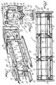
- the optical rule structure with composable modular elements is constituted by a plurality of profiled elements 2 which can be arranged mutually aligned.
- the profiled elements 2 define, in transverse cross section, a substantially U-shaped configuration and have, at the outer edges, longitudinal recesses 4 which are substantially arranged at the ideal corners of a rectangle.
- the profiled elements 2 furthermore advantageously have coupling means constituted by an external dovetail 5 which facilitates fixing of the fixed part.
- the various profiled elements 2 are arrangeable mutually aligned with the interposition of connecting blocks 10 shaped, in their interior, complementarily to the transverse cross section of the profiled elements 2 and having holes 11 with an intermediate abutment wall 12 with a through hole 13.
- Tension elements 15 are accommodated inside the holes 11 and are locked therein by means of screws 16 which couple with the block 10 on the opposite side of the through hole 13.
- the tension elements located between profiled elements which are arranged as continuation of one another are arranged in diagonally and mutually offset recesses so as to not create mutual interference.
- gasket plates 19 are interposed between the connecting blocks 10 and the profiled elements 2 and provide a perfect seal.
- An end plate 20 is furthermore provided which closes the longitudinal ends of the profiled elements and is fixable to the last connecting block.
- a seat 30 is defined at the inner bottom portion of each profiled element, and a continuous band 32, bearing the reference notches and extending throughout the entire length of the optical rule constituted by the mutually aligned portions of profiled element, is insertable in said seat.
- a lateral seat 35 is furthermore provided, and a lateral band 36 which extends throughout the entire length of the optical rule, can be accommodated therein.
- the bands 32 and 36 constitute a continuous path, free from the discontinuities typical of the connecting regions, and consequently provide a continuous path for slideably supporting the reading head 40 of the moving element or slider 41 of the optical rule.
- the band which is generally obtained from a strip of flexible metallic material, can be made in any length and transported to the site of application while coiled, and then inserted into the profiled elements once said profiled elements have been arranged in the required length.
- the bands thus mounted and kept in position by means of the gaskets generally indicated by the reference numeral 50 obtain a continuous path free from obstructions and therefore allow extreme precision and uniformity when sliding of the moving element.
- the gaskets 60 have an insertion head 65 which has reduced dimensions with respect to the longitudinal recess 66 correspondingly provided in the profiled elements 2, so that the gaskets are easily and rapidly insertable with no danger of jamming inside the recesses.
- transverse holes 70 are provided which affect said longitudinal recesses, and a locking pin 71 is insertable therein and has the function of keeping the gaskets perfectly in position, which gaskets are locked at spaced positions along the longitudinal extension of said recesses.
- the invention achieves the proposed aim and objects and in particular the fact is stressed that the adoption of a sliding path for the reading head constituted both by a band bearing the readout notches and extending continuously for the entire length of the profiled elements and by a lateral band which also extends for the entire length allows to obtain an extremely secure support for the reading head, without discontinuities, even if optical rules of considerable length are composed.
- Another important aspect of the invention furthermore resides in that a double series of gaskets is adopted to create a seal between the profiled elements and the moving element or slider, so as to absolutely prevent any infiltration of dust or dirt which could damage or in any way bias the performed readouts.
- the materials employed may be any according to the requirements.
Landscapes
- Physics & Mathematics (AREA)
- General Physics & Mathematics (AREA)
- Securing Of Glass Panes Or The Like (AREA)
Applications Claiming Priority (2)
| Application Number | Priority Date | Filing Date | Title |
|---|---|---|---|
| IT2228087 | 1987-10-14 | ||
| IT8722280A IT1225476B (it) | 1987-10-14 | 1987-10-14 | Struttura di riga ottica ad elementi modulari componibili |
Publications (1)
| Publication Number | Publication Date |
|---|---|
| EP0314940A1 true EP0314940A1 (en) | 1989-05-10 |
Family
ID=11194105
Family Applications (1)
| Application Number | Title | Priority Date | Filing Date |
|---|---|---|---|
| EP88116722A Withdrawn EP0314940A1 (en) | 1987-10-14 | 1988-10-08 | Optical rule structure with composable modular elements |
Country Status (2)
| Country | Link |
|---|---|
| EP (1) | EP0314940A1 (it) |
| IT (1) | IT1225476B (it) |
Cited By (4)
| Publication number | Priority date | Publication date | Assignee | Title |
|---|---|---|---|---|
| WO1997004286A1 (de) * | 1995-07-20 | 1997-02-06 | Carl Zeiss Jena Gmbh | Anordnung zur befestigung einer längenmesseinrichtung |
| WO1997004287A1 (de) * | 1995-07-20 | 1997-02-06 | Carl Zeiss Jena Gmbh | Anordnung zur formschlüssigen aufnahme eines massstabs |
| US6118721A (en) * | 1988-04-18 | 2000-09-12 | Kabushiki Kaisha Toshiba | Random access memory with divided memory banks and data read/write architecture therefor |
| US7356940B2 (en) * | 2004-07-20 | 2008-04-15 | Mitutoyo Corporation | Elastic fixture and attachment method for length measuring apparatus |
Citations (4)
| Publication number | Priority date | Publication date | Assignee | Title |
|---|---|---|---|---|
| US3579836A (en) * | 1968-05-10 | 1971-05-25 | Heidenhain Johannes Dr | Arrangement for measuring of lengths |
| US4160328A (en) * | 1977-06-21 | 1979-07-10 | Dr. Johannes Heidenhain Gmbh | Segmented longitudinal measuring device |
| US4170826A (en) * | 1977-03-22 | 1979-10-16 | Dr. Johannes Heidenhain Gmbh | Longitudinal measuring device with longitudinally displaceable scale |
| US4534113A (en) * | 1983-01-22 | 1985-08-13 | Dr. Johannes Heidenhain Gmbh | Length measuring apparatus |
-
1987
- 1987-10-14 IT IT8722280A patent/IT1225476B/it active
-
1988
- 1988-10-08 EP EP88116722A patent/EP0314940A1/en not_active Withdrawn
Patent Citations (4)
| Publication number | Priority date | Publication date | Assignee | Title |
|---|---|---|---|---|
| US3579836A (en) * | 1968-05-10 | 1971-05-25 | Heidenhain Johannes Dr | Arrangement for measuring of lengths |
| US4170826A (en) * | 1977-03-22 | 1979-10-16 | Dr. Johannes Heidenhain Gmbh | Longitudinal measuring device with longitudinally displaceable scale |
| US4160328A (en) * | 1977-06-21 | 1979-07-10 | Dr. Johannes Heidenhain Gmbh | Segmented longitudinal measuring device |
| US4534113A (en) * | 1983-01-22 | 1985-08-13 | Dr. Johannes Heidenhain Gmbh | Length measuring apparatus |
Cited By (6)
| Publication number | Priority date | Publication date | Assignee | Title |
|---|---|---|---|---|
| US6118721A (en) * | 1988-04-18 | 2000-09-12 | Kabushiki Kaisha Toshiba | Random access memory with divided memory banks and data read/write architecture therefor |
| WO1997004286A1 (de) * | 1995-07-20 | 1997-02-06 | Carl Zeiss Jena Gmbh | Anordnung zur befestigung einer längenmesseinrichtung |
| WO1997004287A1 (de) * | 1995-07-20 | 1997-02-06 | Carl Zeiss Jena Gmbh | Anordnung zur formschlüssigen aufnahme eines massstabs |
| US5987768A (en) * | 1995-07-20 | 1999-11-23 | Carl Zeiss Jena Gmbh | Arrangement for fastening a length measurement device |
| US6105271A (en) * | 1995-07-20 | 2000-08-22 | Johannes Heidenhain Gmbh | Arrangement for accommodating a scale in a positive engagement |
| US7356940B2 (en) * | 2004-07-20 | 2008-04-15 | Mitutoyo Corporation | Elastic fixture and attachment method for length measuring apparatus |
Also Published As
| Publication number | Publication date |
|---|---|
| IT8722280A0 (it) | 1987-10-14 |
| IT1225476B (it) | 1990-11-14 |
Similar Documents
| Publication | Publication Date | Title |
|---|---|---|
| CA2246451C (en) | Energy guide chain with guide stop | |
| US4441278A (en) | Mounting for endless sealing strips | |
| US4854473B1 (it) | ||
| US3779003A (en) | Cable carrier with removable plastic links | |
| EP0314940A1 (en) | Optical rule structure with composable modular elements | |
| KR940011373B1 (ko) | 활주편을 구비한 동력 공급 라인용 안내 체인 | |
| US5829885A (en) | Shaft supported linear motion guide system | |
| EP0119670B1 (en) | Cable ladder | |
| DE69808142T2 (de) | Schnellbefestigungsvorrichtung für eine armbanduhr | |
| CA1121157A (en) | Name plate system | |
| CA2178162A1 (en) | Modular cabinet and drawer assembly | |
| CA1196037A (en) | Corner guide assembly | |
| US11365059B2 (en) | Support structure with improved stiffness for an articulated link conveyor | |
| EP0671537B1 (en) | Universal support means for the side guides of a rolling shutter | |
| KR920001049A (ko) | 거프집용 프레임 | |
| SE436589B (sv) | Cylinderlas | |
| EP0404240B1 (en) | Snap connection system, in particular for electrical installation cabinets | |
| KR200218388Y1 (ko) | 벨트 콘베이어의 밀폐형 장력유지장치 | |
| JP2002147139A (ja) | シャッタ | |
| GB2159864A (en) | Window constructions | |
| GB2211242A (en) | Spring-biased hinge | |
| GB2166464A (en) | Gutters | |
| GB2055413A (en) | Tunnel segments | |
| GB2186656A (en) | Improved sewer or tunnel lining | |
| FI102331B (fi) | Kaapeliohjain |
Legal Events
| Date | Code | Title | Description |
|---|---|---|---|
| PUAI | Public reference made under article 153(3) epc to a published international application that has entered the european phase |
Free format text: ORIGINAL CODE: 0009012 |
|
| AK | Designated contracting states |
Kind code of ref document: A1 Designated state(s): AT DE ES FR GB IT |
|
| 17P | Request for examination filed |
Effective date: 19890922 |
|
| 17Q | First examination report despatched |
Effective date: 19901107 |
|
| STAA | Information on the status of an ep patent application or granted ep patent |
Free format text: STATUS: THE APPLICATION IS DEEMED TO BE WITHDRAWN |
|
| 18D | Application deemed to be withdrawn |
Effective date: 19910319 |