EP0314839A1 - Positioning apparatus - Google Patents
Positioning apparatus Download PDFInfo
- Publication number
- EP0314839A1 EP0314839A1 EP87202174A EP87202174A EP0314839A1 EP 0314839 A1 EP0314839 A1 EP 0314839A1 EP 87202174 A EP87202174 A EP 87202174A EP 87202174 A EP87202174 A EP 87202174A EP 0314839 A1 EP0314839 A1 EP 0314839A1
- Authority
- EP
- European Patent Office
- Prior art keywords
- elements
- elongatable
- axially
- cylinder
- interior
- Prior art date
- Legal status (The legal status is an assumption and is not a legal conclusion. Google has not performed a legal analysis and makes no representation as to the accuracy of the status listed.)
- Granted
Links
Images


Classifications
-
- F—MECHANICAL ENGINEERING; LIGHTING; HEATING; WEAPONS; BLASTING
- F16—ENGINEERING ELEMENTS AND UNITS; GENERAL MEASURES FOR PRODUCING AND MAINTAINING EFFECTIVE FUNCTIONING OF MACHINES OR INSTALLATIONS; THERMAL INSULATION IN GENERAL
- F16M—FRAMES, CASINGS OR BEDS OF ENGINES, MACHINES OR APPARATUS, NOT SPECIFIC TO ENGINES, MACHINES OR APPARATUS PROVIDED FOR ELSEWHERE; STANDS; SUPPORTS
- F16M11/00—Stands or trestles as supports for apparatus or articles placed thereon Stands for scientific apparatus such as gravitational force meters
- F16M11/02—Heads
- F16M11/18—Heads with mechanism for moving the apparatus relatively to the stand
-
- B—PERFORMING OPERATIONS; TRANSPORTING
- B23—MACHINE TOOLS; METAL-WORKING NOT OTHERWISE PROVIDED FOR
- B23Q—DETAILS, COMPONENTS, OR ACCESSORIES FOR MACHINE TOOLS, e.g. ARRANGEMENTS FOR COPYING OR CONTROLLING; MACHINE TOOLS IN GENERAL CHARACTERISED BY THE CONSTRUCTION OF PARTICULAR DETAILS OR COMPONENTS; COMBINATIONS OR ASSOCIATIONS OF METAL-WORKING MACHINES, NOT DIRECTED TO A PARTICULAR RESULT
- B23Q1/00—Members which are comprised in the general build-up of a form of machine, particularly relatively large fixed members
- B23Q1/25—Movable or adjustable work or tool supports
- B23Q1/44—Movable or adjustable work or tool supports using particular mechanisms
- B23Q1/48—Movable or adjustable work or tool supports using particular mechanisms with sliding pairs and rotating pairs
-
- B—PERFORMING OPERATIONS; TRANSPORTING
- B25—HAND TOOLS; PORTABLE POWER-DRIVEN TOOLS; MANIPULATORS
- B25J—MANIPULATORS; CHAMBERS PROVIDED WITH MANIPULATION DEVICES
- B25J17/00—Joints
- B25J17/02—Wrist joints
- B25J17/0258—Two-dimensional joints
- B25J17/0266—Two-dimensional joints comprising more than two actuating or connecting rods
-
- B—PERFORMING OPERATIONS; TRANSPORTING
- B25—HAND TOOLS; PORTABLE POWER-DRIVEN TOOLS; MANIPULATORS
- B25J—MANIPULATORS; CHAMBERS PROVIDED WITH MANIPULATION DEVICES
- B25J9/00—Programme-controlled manipulators
- B25J9/003—Programme-controlled manipulators having parallel kinematics
- B25J9/0072—Programme-controlled manipulators having parallel kinematics of the hybrid type, i.e. having different kinematics chains
-
- B—PERFORMING OPERATIONS; TRANSPORTING
- B25—HAND TOOLS; PORTABLE POWER-DRIVEN TOOLS; MANIPULATORS
- B25J—MANIPULATORS; CHAMBERS PROVIDED WITH MANIPULATION DEVICES
- B25J9/00—Programme-controlled manipulators
- B25J9/02—Programme-controlled manipulators characterised by movement of the arms, e.g. cartesian coordinate type
-
- B—PERFORMING OPERATIONS; TRANSPORTING
- B25—HAND TOOLS; PORTABLE POWER-DRIVEN TOOLS; MANIPULATORS
- B25J—MANIPULATORS; CHAMBERS PROVIDED WITH MANIPULATION DEVICES
- B25J9/00—Programme-controlled manipulators
- B25J9/10—Programme-controlled manipulators characterised by positioning means for manipulator elements
- B25J9/14—Programme-controlled manipulators characterised by positioning means for manipulator elements fluid
- B25J9/144—Linear actuators
-
- F—MECHANICAL ENGINEERING; LIGHTING; HEATING; WEAPONS; BLASTING
- F16—ENGINEERING ELEMENTS AND UNITS; GENERAL MEASURES FOR PRODUCING AND MAINTAINING EFFECTIVE FUNCTIONING OF MACHINES OR INSTALLATIONS; THERMAL INSULATION IN GENERAL
- F16H—GEARING
- F16H25/00—Gearings comprising primarily only cams, cam-followers and screw-and-nut mechanisms
- F16H25/18—Gearings comprising primarily only cams, cam-followers and screw-and-nut mechanisms for conveying or interconverting oscillating or reciprocating motions
- F16H25/20—Screw mechanisms
- F16H25/2003—Screw mechanisms with arrangements for taking up backlash
-
- F—MECHANICAL ENGINEERING; LIGHTING; HEATING; WEAPONS; BLASTING
- F16—ENGINEERING ELEMENTS AND UNITS; GENERAL MEASURES FOR PRODUCING AND MAINTAINING EFFECTIVE FUNCTIONING OF MACHINES OR INSTALLATIONS; THERMAL INSULATION IN GENERAL
- F16H—GEARING
- F16H57/00—General details of gearing
- F16H57/04—Features relating to lubrication or cooling or heating
- F16H57/048—Type of gearings to be lubricated, cooled or heated
- F16H57/0497—Screw mechanisms
-
- F—MECHANICAL ENGINEERING; LIGHTING; HEATING; WEAPONS; BLASTING
- F16—ENGINEERING ELEMENTS AND UNITS; GENERAL MEASURES FOR PRODUCING AND MAINTAINING EFFECTIVE FUNCTIONING OF MACHINES OR INSTALLATIONS; THERMAL INSULATION IN GENERAL
- F16M—FRAMES, CASINGS OR BEDS OF ENGINES, MACHINES OR APPARATUS, NOT SPECIFIC TO ENGINES, MACHINES OR APPARATUS PROVIDED FOR ELSEWHERE; STANDS; SUPPORTS
- F16M11/00—Stands or trestles as supports for apparatus or articles placed thereon Stands for scientific apparatus such as gravitational force meters
- F16M11/02—Heads
- F16M11/04—Means for attachment of apparatus; Means allowing adjustment of the apparatus relatively to the stand
- F16M11/06—Means for attachment of apparatus; Means allowing adjustment of the apparatus relatively to the stand allowing pivoting
- F16M11/12—Means for attachment of apparatus; Means allowing adjustment of the apparatus relatively to the stand allowing pivoting in more than one direction
- F16M11/126—Means for attachment of apparatus; Means allowing adjustment of the apparatus relatively to the stand allowing pivoting in more than one direction for tilting and panning
-
- F—MECHANICAL ENGINEERING; LIGHTING; HEATING; WEAPONS; BLASTING
- F16—ENGINEERING ELEMENTS AND UNITS; GENERAL MEASURES FOR PRODUCING AND MAINTAINING EFFECTIVE FUNCTIONING OF MACHINES OR INSTALLATIONS; THERMAL INSULATION IN GENERAL
- F16M—FRAMES, CASINGS OR BEDS OF ENGINES, MACHINES OR APPARATUS, NOT SPECIFIC TO ENGINES, MACHINES OR APPARATUS PROVIDED FOR ELSEWHERE; STANDS; SUPPORTS
- F16M11/00—Stands or trestles as supports for apparatus or articles placed thereon Stands for scientific apparatus such as gravitational force meters
- F16M11/20—Undercarriages with or without wheels
- F16M11/2007—Undercarriages with or without wheels comprising means allowing pivoting adjustment
- F16M11/2021—Undercarriages with or without wheels comprising means allowing pivoting adjustment around a horizontal axis
-
- F—MECHANICAL ENGINEERING; LIGHTING; HEATING; WEAPONS; BLASTING
- F16—ENGINEERING ELEMENTS AND UNITS; GENERAL MEASURES FOR PRODUCING AND MAINTAINING EFFECTIVE FUNCTIONING OF MACHINES OR INSTALLATIONS; THERMAL INSULATION IN GENERAL
- F16M—FRAMES, CASINGS OR BEDS OF ENGINES, MACHINES OR APPARATUS, NOT SPECIFIC TO ENGINES, MACHINES OR APPARATUS PROVIDED FOR ELSEWHERE; STANDS; SUPPORTS
- F16M2200/00—Details of stands or supports
- F16M2200/04—Balancing means
- F16M2200/044—Balancing means for balancing rotational movement of the undercarriage
-
- Y—GENERAL TAGGING OF NEW TECHNOLOGICAL DEVELOPMENTS; GENERAL TAGGING OF CROSS-SECTIONAL TECHNOLOGIES SPANNING OVER SEVERAL SECTIONS OF THE IPC; TECHNICAL SUBJECTS COVERED BY FORMER USPC CROSS-REFERENCE ART COLLECTIONS [XRACs] AND DIGESTS
- Y10—TECHNICAL SUBJECTS COVERED BY FORMER USPC
- Y10T—TECHNICAL SUBJECTS COVERED BY FORMER US CLASSIFICATION
- Y10T74/00—Machine element or mechanism
- Y10T74/18—Mechanical movements
- Y10T74/18568—Reciprocating or oscillating to or from alternating rotary
- Y10T74/18576—Reciprocating or oscillating to or from alternating rotary including screw and nut
- Y10T74/18584—Shaft shorter than nut
-
- Y—GENERAL TAGGING OF NEW TECHNOLOGICAL DEVELOPMENTS; GENERAL TAGGING OF CROSS-SECTIONAL TECHNOLOGIES SPANNING OVER SEVERAL SECTIONS OF THE IPC; TECHNICAL SUBJECTS COVERED BY FORMER USPC CROSS-REFERENCE ART COLLECTIONS [XRACs] AND DIGESTS
- Y10—TECHNICAL SUBJECTS COVERED BY FORMER USPC
- Y10T—TECHNICAL SUBJECTS COVERED BY FORMER US CLASSIFICATION
- Y10T74/00—Machine element or mechanism
- Y10T74/18—Mechanical movements
- Y10T74/18568—Reciprocating or oscillating to or from alternating rotary
- Y10T74/18576—Reciprocating or oscillating to or from alternating rotary including screw and nut
- Y10T74/18744—Lubrication
-
- Y—GENERAL TAGGING OF NEW TECHNOLOGICAL DEVELOPMENTS; GENERAL TAGGING OF CROSS-SECTIONAL TECHNOLOGIES SPANNING OVER SEVERAL SECTIONS OF THE IPC; TECHNICAL SUBJECTS COVERED BY FORMER USPC CROSS-REFERENCE ART COLLECTIONS [XRACs] AND DIGESTS
- Y10—TECHNICAL SUBJECTS COVERED BY FORMER USPC
- Y10T—TECHNICAL SUBJECTS COVERED BY FORMER US CLASSIFICATION
- Y10T74/00—Machine element or mechanism
- Y10T74/20—Control lever and linkage systems
- Y10T74/20207—Multiple controlling elements for single controlled element
- Y10T74/20341—Power elements as controlling elements
Abstract
Description
- The present invention relates to mechanical devices generally and more specifically to positioning apparatus including electrically actuable pistons and two and three dimensional positioners.
- X-Y tables of various designs are known and typically comprise a plurality of screw drives arranged along perpendicular axes. Due to the requirement for independent X, Y motion, part of the drives, including their power sources, are required to move. As a result, X-Y tables are generally complex and expensive.
- Robots of various designs are known. Typically, prior art robots comprise extensible members which are arranged for selectable extension along relatively perpendicular axes.
- Various types of positioning apparatus are known on the market. Specifically, electrically actuable cylinders are known. One typical device of this type is a Model 15D manufactured by Industrial Devices Corporation of Novato, California, U.S.A.. This electric cylinder includes a fixed outer housing, a fixed screw thread rotatably mounted in the housing and a translatable riding member which translates axially in response to rotation of the screw thread. A piston extension member is mounted for movement together with the translatable riding member.
- The above-described device is lubricated with grease, and cannot, as a matter of practicality, be filled with oil because too many seals would be required and no provision was made for accomodating the change in interior volume due to differing displacements of the piston.
- Electrically acutuable cylinders of the type described hereinabove are relatively expensive due to their complexity. Due to the fact that they are lubricated with grease, having relatively poor heat distribution characteristics as compared with oil, their mechanical efficiency and operating lifetime are relatively low.
- The present invention seeks to improve such known positioning apparatus as to simplicity, versatility, applicability and reliability and to improve such electrically actuable cylinders to overcome the described disadvantages of the prior art cylinders and to make them most suitable for use in such positioning apparatus such as X Y-tables and RR and RRR-robots.
- There is thus in accordance with the present invention provided positioning apparatus comprising an element to be positioned, and first and second axially elongatable elements mounted onto the element to be positioned at first and second locations thereat and to support locations, at least one of the first and second axially elongatable elements being pivotably mounted onto the element to be positioned and at least one of the first and second axially elongatable elements being pivotably mounted onto a support location.
- Additionally in accordance with an embodiment of the present invention, at least three axially elongatable elements are employed.
- Further in accordance with an embodiment of the present invention there is provided a three dimensional positioning device comprising a base, a first element pivotably mounted with respect to the base for pivotable positioning relative to the base about a first pivot axis, a second element pivotably mounted with respect to the first element for pivotable positioning relative thereto about a second pivot axis perpendicaular to the first pivot axis, first axially elongatable means mounted onto the base and either of the first and second elements for selectable positioning of the second element about the first pivot axis and second axially elongatable means mounted onto the base and the second element for selectable positioning of the second element with respect to both the first and second pivot axes.
- In accordance with a preferred embodiment of the present invention, the second axially elongatable means comprises two axially elongatable elements arranged in a plane typically parallel to the first pivot axis and having elongation axes which are angled with respect to each other. In accordance with a preferred embodiment of the invention, the two axially elongatable elements operate in a differential mode of operation.
- In accordance with an embodiment of the invention, at least some of the base, first element, second element, first axially elongatable means and second axially elongatable means are pivotably interconnected by universal joints.
- Further, in accordance with a preferred embodiment of the present invention an electrically actuable cylinder comprises a first element defning a cylinder housing and defining an interior generally cylindrical screw threading, a second element defining an interior member and located within the cylinder housing and defining an exterior generally cylindrical screw threading which cooperates with the interior generally cylindrical screw threading of the first element, whereby relative rotation of the first and second elements in a first rotation direction produces translation of the second element relative to the first element in a first axial direction, and relative rotation of the first and second elements in a second, opposite, rotation direction, produces translation of the second element relative to the first element, in a second axial direction, opposite to the first axial direction.
- Additionally in accordance with an embodiment of the present invention, the first and second elements are each provided with mounting elements for secure attachment thereof to driving or driven elements.
- Further in accordance with an embodiment of the present invention, the interior of the first element is filled with lubricating fluid.
- Additionally in accordance with a preferred embodiment of the invention, a lubricating fluid reservoir is provided in communication with the interior of the first element and is sealed from the exterior thereof.
- Further in accordance with an embodiment of the present invention, the lubricating fluid reservoir communicates with the interior of the first element through a plurality of apertures formed along the length thereof.
- Additionally in accordance with an embodiment of the present invention, the lubricating fluid reservoir includes a resiliently flexible portion for adapting to the varying interior volume of the first element as a function of the relative location of the second element therein.
- Further in accordance with an embodiment of the invention, the electrically actuable cylinder includes means operative to reduce backlash. In one such embodiment, the second element comprises at least first and second threaded elements flexibly joined.
- Additionally in accordance with a preferred embodiment of the present invention, the first and second elements are axially tensioned.
- The present invention will be understood and appreciated more fully from the following detailed description taken in conjunction with the drawings in which:
- Figs. 1A and 1B are side sectional illustrations of an electrically actuable cylinder constructed and operative in accordance with an embodiment of the present invention in respective extended and retracted orientations;
- Figs. 2A, 2B and 2C are sectional illustrations of three embodiments of the cylinder of Figs. 1A and 1B taken along the lines II - II of Fig. 1B;
- Fig. 3 is a side sectional illustration of an electrically actuable cylinder constructed and operative in accordance with a preferred embodiment of the present invention;
- Fig. 4 is a sectional illustration of the cylinder of Fig. 3, taken along the lines IV - IV of Fig. 3;
- Figs. 5A and 5B are respective side and side sectional illustrations of an anti-backlash type of interconnection preferably employed in the cylinder of Figs. 1 - 4;
- Fig. 6 is a sectional illustration of a rigid coupling useful in various embodiments of the present invention;
- Fig. 7 is a pictorial illustration of a slotted threaded collar member useful in the embodiment of Fig. 6;
- Fig. 8 is an illustration of a cylinder of the type illustrated in Figs. 1 - 4 in a typical operating orientation;
- Figs. 9A, 9B, 9C, 9D and 9E are top view illustrations of an X-Y table constructed and operative in accordance with one preferred embodiment of the invention in various operative orientations;
- Figs. 10A, 10B, 10C, 10D, 10E, 10F and 10G are top view illustrations of an X-Y table constructed and operative in accordance with another preferred embodiment of the invention in various operative orientations;
- Figs. 11A, 11B and 11C are respective pictorial, side and end view illustrations of a robot constructed and operative in accordance with a preferred embodiment of the present invention;
- Figs. 12A, 12B, 12C and 12D are side view illustrations of the robot of Figs. 11A - 11C in four alternative operative orientations; and
- Figs. 13A and 13B are end view illustrations of the robot of Figs. 11A - 11C in two alternative operative orientations.
- Reference is now made to Figs. 1A and 1B which illustrate an electrically actuable cylinder constructed and operative in accordance with an embodiment of the present invention and suitable for horizontal disposition. The cylinder comprises a
cylinder housing 10 having inwardly facing screw threading 12, an externally threadedpiston mounting member 14 and apiston 16, mounted ontomounting member 14. - The
cylinder housing 10 is preferably formed with amounting portion 18 including amounting aperture 20, for fixed mounting thereof, in a manner which will be described hereinafter in connection with Fig. 8. Thecylinder housing 10 is also formed with a lubrication inlet andoutlet aperture 22, communicating with the interior of thecylinder housing 10 and having an associatedplug 24. Disposed interior of the cylinder housing is a liquid lubricant, typically oil. - At the opposite end of the cylinder housing from
aperture 22 there is provided apiston seal 25 andbushing 26, typically held in place by a sealingring 28, all of conventional construction. - A comparison of Figs. 1A and 1B illustrates the relative displacement of the mounting
member 14 andpiston 16 axially along thelongitudinal axis 30 of the cylinder. It will be appreciated that relative rotation of thepiston mounting member 14 and ofcylinder housing 10 in a first rotational direction produces axial displacement of the piston relative to the housing in a first axial direction alongaxis 30, while relative rotation of thepiston mounting member 14 and thecylinder housing 10 in an opposite rotational direction produces axial displacement in an opposite direction. - Considering now Figs. 2A - 2C, it is seen that there are a number of alternatives for the configuration of the
cylinder housing 10. Three of these alternatives are illustrated, it being noted that the embodiment of 2A shows a square cross section, in which fourcorner spaces 32 are left between thepiston mounting member 14 and the housing to permit oil to pass therethrough as the mountingmember 14 moves axially alongaxis 30. - Fig. 2B shows a triangular configuration of
housing 10 providing threecorner spaces 34. Fig. 2C shows a generally rounded configuration having a mountingmember 14 having a plurality ofaxial slots 35 formed therein to permit passage therethrough of lubricating fluid, such as oil. Such slots or similar means may also be present in all other embodiments of the cylinder to avoid jamming by enclosed quantities of lubricating fluid to one side of the piston mounting member. - Reference is now made to Figs. 3 and 4 which illustrate an alternative embodiment of an electrically actuable cylinder constructed and operative in accordance with a preferred embodiment of the present invention. Similarly to the embodiment of Figs. 1A and 1B, the cylinder comprises a
cylinder housing 40 having inwardly facing screw threading 42, an externally threadedpiston mounting member 44 and apiston 46, mounted onto mountingmember 44. - The
cylinder housing 40 is preferably formed with a mountingportion 48 including a mountingaperture 50, for fixed mounting thereof, in a manner which will be described hereinafter in connection with Fig. 8. Thecylinder housing 40 is also formed with a lubrication inlet andoutlet aperture 52, communicating with the interior of thecylinder housing 40 and having an associatedplug 54. Filling the interior of the cylinder housing is a liquid lubricant, typically oil. - At the opposite end of the cylinder housing from
aperture 52 there is provided apiston seal 55 andbushing 56, typically held in place by a sealingring 58, all of conventional construction. - In contrast to the embodiment of Figs. 1A and 1B, the embodiment of Figs. 3 and 4 is characterized in that it is provided with means for accomodating excess oil which is expelled from the interior of the
cylinder housing 40, when thepiston 46 is retracted, thereinto, thereby reducing the interior volume. Accordingly, the embodiment of Figs. 3 and 4 may be used at any desired orientation, not necessarily horizontal. - The means for accomodating excess oil typically comprises a
bladder 60 formed of a resilient material, such as rubber, which surrounds thecylinder housing 40 and is fixedly attached thereto at the extreme ends thereof 62 and 64. - The interior of the
blader 60 typically communicates with the interior of thecylinder housing 40 via a series of apertures 66 formed along the length of thecylinder housing 40. Thebladder 40 is enclosed by a relativelyrigid cover member 68. It is a particular feature of the invention that adjacent to the rear portion of thecylinder housing 40, i.e. nearplug 54, no apertures 66 are defined. Thus, when the mountingmember 44 is fully retracted, it does not tend to get stuck in the retracted orientation, due to a deposit of compressed lubricating oil disposed between the mountingmember 44 and therear wall 69 of the cylinder. Another advantage of this construction is to cushion impacts at the extreme positions of the mountingmember 44. - Similarly to the operation of the apparatus of Figs. 1A and 1B, relative displacement of the mounting
member 44 andpiston 46 axially along thelongitudinal axis 70 of the cylinder is produced by relative rotation of thepiston mounting member 44 and ofcylinder housing 40. - It has been appreciated that problems of backlash sometimes occur in electrically actuable cylinders of the type considered herein. In order to overcome this problem, a special construction is provided in accordance with the present invention, and illustrated in Figs. 5A and 5V whereby a piston mounting member 74 (which may be substituted for
members 14 and 44) is formed to define a flexible mounting for a corresponding piston 76 (which may be substituted formembers 16 and 46). - In the illustrated embodiment of Figs. 5A and 5B, a
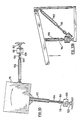
piston mounting member 74 is formed withtransverse slots 78 which effectively define twoportions axis 84 but rigid with respect to tortional displacement relative thereto. Thepiston 76 is fixedly mounted ontoporiton 82 and an arrangement is provided wherebyportions longitudinal axis 84, as by atensioning screw 86 forcingportions - Reference is now made to Fig. 8, which illustrates the environment in which the cylinders of Figs. 1 - 7 operate. Here such a
cylinder 90 is shown having thecylinder housing 92 pivotably but not rotatably mounted onto amovable element 94. Thepiston 96 is mounted, typically via arigid coupling 98 to thespindle 99 of anelectric motor 100, whose base is pivotably, but not rotatably mounted onto a fixed mountingsupport 102. Rotation of thepiston 96 about itslongitudinal axis 104 in either direction provides either extension or retraction of thepiston 96 relative tohousing 92, thus providing displacement ofmember 94 alongarrows 106. -
Rigid coupling 98 is illustrated in Figs. 6 and 7 which comprises a threaded axially slottedsleeve 107 which is arranged to overlie two shafts, which may be of different diameters and to be tightened thereover by corresponding pairs ofnuts sleeve 107 radially inwardly. - Reference is now made to Figs. 9A - 9E, which illustrate an X - Y table constructed and operative in accordance with a preferred embodiment of the present invention. According to a preferred embodiment of the invention, the X - Y table comprises a
table member 110 arranged for motion in an X - Y plane and having fixed thereto a first electricallyactuable cylinder 112.Cylinder 112 is preferably a cylinder of the type described hereinabove in connection with Figs. 1 - 8 but may alternatively be a prior art cylinder or any other suitable cylinder. - A
piston 114 ofcylinder 112 is mounted, typically viacoupling 116, typically of the type shown in Figs. 6 and 7, to thespindle 118 of anelectric motor 120, whose base is pivotably, but not rotatably, mounted onto a fixed mountingsupport 122. - Pivotably mounted onto
table member 110 about a pivot axis perpendicular to the X - Y plane and extending generally perpendicular tocylinder 112 is an electricallyactuable cylinder 124,Cylinder 124 is preferably a cylinder of the type described hereinabove in connection with Figs. 1 - 8 but may alternatively be a prior art cylinder or any other suitable cylinder. - A
piston 125 ofcylinder 124 is mounted, typically via acoupling 126, typically of the type shown in Figs. 6 and 7, onto thespindle 128 of anelectric motor 130, whose base is pivotably, but not rotatably, mounted onto a fixed mountingsupport 132. - Fig. 9A shows the
table member 110 in a nominal intermediate position, with bothpistons pistion 114 is fully extended; Fig. 9C shows the orientation whenpiston 114 is fully retracted; Fig. 9D shows the orientation whenpiston 125 is fully retracted; and Fig. 9E shows the orientation whenpiston 125 is fully extended. - It is appreciated that when
table member 110 is out of its nominal position, it is skewed in the X - Y plane. For applications wherein the rotational orientation of thetable member 110 is of significance, an alternative construction of an X - Y table is provided, as illustrated in Figs. 10A - 10G. - According to a preferred embodiment of the invention, the X - Y table of Figs. 10A - 10G comprises a
table member 130 arranged for motion in an X - Y plane and having pivotably mounted thereto about pivot axes lying perpendicular to the X - Y plane three electricallyactuable cylinders -
Cylinders table member 130, whilecylinder 136 is arranged generally perpendicularly tocylinders table member 130, separated from the first side by 90 degrees. -
Pistons respective cylinders respective couplings spindles electric motors - A
piston 162 ofcylinder 136 is mounted, typically via acoupling 164, typically of the type shown in Figs. 6 and 7, to thespindle 166 of anelectric motor 168, whose base is pivotably, but not rotatably, mounted onto a fixed mountingsupport 170. - Fig. 10A shows the
table member 130 in a nominal intermediate position, withpistons pistons pistons piston 162 is fully retracted; Fig. 10E shows the orientation whenpiston 162 is fully extended; Fig. 10F shows rotation of thetable member 130 about its nominal position of Fig. 10A in a first direction and Fig. 10G shows rotation of thetable member 130 about its nominal position of Fig. 10B in an opposite direction. - Reference is now made to Figs. 11A - 11C which illustrate 3-dimensional positioning apparatus constructed and operative in accordance with a preferred embodiment of the invention and comprising a
base 180 and afirst element 182, typically in the form of a sawhorse bracket, pivotably mounted with respect to thebase 180 for pivotable positioning relative to the base about afirst pivot axis 184, typically lying parallel to the plane of thebase 180. - A
second element 186, typically in the form of a beam, is pivotably mounted with respect to thefirst element 188, preferably by auniversal joint 187, which permits rotation of thesecond element 186 about the first pivot axis and also with respect to a second pivot axis perpendicular to the first pivot axis. - First axially elongatable means 188, typically in the form of an electrically actuable cylinder of the type described above and illustrated in Figs. 1 - 8, but alternatively any suitably elongatable means, is mounted onto the
base 180 and thefirst element 182 for selectable positioning of the first element about the first pivot axis, in much the same arrangement illustrated in Fig. 8 hereinabove. - Second axially elongatable means, typically in the form of a pair of electrically actuable cyliners 190 and 192, are mounted onto the
base 180 and onto thesecond element 186 for selectable positioning of the second element with respect to both the first and second pivot axes. It is noted that each of the electrically actuable cylinders is provided with a driving and coupling assembly of the type shown in Fig. 8. It is appreciated that thecylinders - According to an alternative embodiment of the invention,
cylinder 188 may be coupled directly toelement 186 instead of being coupled toelement 182. In such alternative embodiment, the threecylinders element 186 at the same general location. - Figs. 11A-11C illustrate the positioning apparatus in a nominal position with all of the pistons in intermediate positions. Fig. 12A illustrates the positioning apparatus in a raised position, wherein
pistons respective cylinders pistons respective cylinders - Fig. 12C illustrates the positioning apparatus in a backward position, wherein
piston 198 ofcylinder 188 is fully extended, and Fig. 12D illustrates the positioning apparatus in a forward position, whereinpiston 198 ofcylinder 188 is fully retracted. - Fig. 13A illustrates the positioning apparatus in a left-sided orientation wherein
piston 196 is extended more thanpiston 194 while Fig. 13B illustrates the positioning apparatus in a right-sided orientation whereinpiston 194 is extended more thanpiston 196. - The table 110 and the
beam 186 may be used for any suitable purpose in positioning parts, e.g. to be machined, or to position tools or measuring and sensing means, as is known as such in the art, e.g. in robots for handling and machining. The free end ofbeam 186, to be positioned accurately in space as described, may carry gripping means not shown and known as such, to grip articles to be treated, machined or operated on in any other manner, to move such articles to a treatment zone, to hold them during treatment if so desired, and to move them back to the point where they were thus gripped, or only to convey articles from one point to another etc. The purpose may be to save manual labor, to avoid heavy loads having to be moved by personnel, to speed up treatments, to obtain more accurate positioning of articles, to hold them exactly in place during longer time intervals and/or to exert any of such operations in an environment dangerous to men or not easily accessible to personnel etc. - It will be appreciated by persons skilled in the art that the examples provided above are merely illustrative of the structure and operation of the apparatus of the present invention. The present invention is not defined by what is described hereinabove but rather the scope of the invention is limited only by the claims which follow.
Claims (17)
a first element pivotably mounted with respect to the base for pivotable positioning relative to the base about a first pivot axis;
a second element pivotably mounted with respect to the first element for pivotable positioning relative thereto about a second pivot axis generally perpendicular to the first pivot axis;
first axially elongatable means mounted onto the base and to either the first element or the second element for selectable positioning of the second element about the first pivot axis; and
second axially elongatable means mounted onto the base and the second element for selectable positioning of the second element with respect to both the first and second pivot axes.
a second element defining an interior member located within the cylinder housing and defining an exterior generally cylindrical screw threading which cooperates with the interior generally cylindrical screw threading of the first element, whereby relative rotation of the first and second elements in a first rotation direction produces translation of the second element relative to the first element in a first axial direction, and relative rotation of the first and second elements in a second opposite rotation direction, produces translation of the second element relative to the first element in a second axial direction, opposite to the first axial direction.
Priority Applications (2)
| Application Number | Priority Date | Filing Date | Title |
|---|---|---|---|
| AT87202174T ATE96719T1 (en) | 1987-11-06 | 1987-11-06 | POSITIONING DEVICE. |
| DE19873788065 DE3788065T2 (en) | 1987-11-06 | 1987-11-06 | Positioning device. |
Applications Claiming Priority (1)
| Application Number | Priority Date | Filing Date | Title |
|---|---|---|---|
| IL77654A IL77654A (en) | 1986-01-20 | 1986-01-20 | Electric positioning apparatus |
Publications (2)
| Publication Number | Publication Date |
|---|---|
| EP0314839A1 true EP0314839A1 (en) | 1989-05-10 |
| EP0314839B1 EP0314839B1 (en) | 1993-11-03 |
Family
ID=11056509
Family Applications (1)
| Application Number | Title | Priority Date | Filing Date |
|---|---|---|---|
| EP87202174A Expired - Lifetime EP0314839B1 (en) | 1986-01-20 | 1987-11-06 | Positioning apparatus |
Country Status (4)
| Country | Link |
|---|---|
| US (1) | US4872363A (en) |
| EP (1) | EP0314839B1 (en) |
| ES (1) | ES2044913T3 (en) |
| IL (1) | IL77654A (en) |
Cited By (16)
| Publication number | Priority date | Publication date | Assignee | Title |
|---|---|---|---|---|
| WO1990006214A1 (en) * | 1988-11-28 | 1990-06-14 | Fredrik Bror Bengt Lagercrantz | An arrangement for bringing the tool-carrying end of a robot beam to a desired one of a plurality of possible, predetermined positions |
| EP0437741A2 (en) * | 1990-01-16 | 1991-07-24 | International Business Machines Corporation | A two-dimensional positioning apparatus |
| EP0791438A2 (en) * | 1996-02-07 | 1997-08-27 | Verein Deutscher Werkzeugmaschinenfabriken e.V. (VDW) | Device for moving a body in space |
| NL1015816C2 (en) * | 2000-07-27 | 2002-01-29 | R P T Weekers Holding B V | Manipulator or industrial robot has column fixed to floor and at upper side column is connected with extending part, which can hinge around horizontal axis, for which two bearing parts are fixed to column |
| EP1618394A2 (en) * | 2003-03-31 | 2006-01-25 | Intest Ip Corp. | Test head positioning system and method |
| FR2901596A1 (en) * | 2006-05-24 | 2007-11-30 | Agence Spatiale Europeenne | Body e.g. mobile platform, and fixed base connecting mechanism for e.g. aerospace industry, has four links, each being connected to fixed base and mobile platform, by connection points, respectively, where links are formed by cables |
| EP2165886A1 (en) | 2008-09-18 | 2010-03-24 | SMR PATENTS S.à.r.l. | Rear view mirror |
| WO2012089852A1 (en) * | 2010-12-30 | 2012-07-05 | Ideko, S. Coop. | Machine tool guide bench |
| CN104149086A (en) * | 2014-08-20 | 2014-11-19 | 苏州昌飞自动化设备厂 | Lifting arm provided with fine adjustment seat and used for lifting sucker mechanical arm capable of performing three-dimensional fine adjustment |
| US10261648B2 (en) | 2009-10-07 | 2019-04-16 | Magna Mirrors Of America, Inc. | Exterior rearview mirror assembly |
| US10913395B2 (en) | 2010-02-10 | 2021-02-09 | Magna Mirrors Of America, Inc. | Exterior rearview mirror assembly |
| US11148596B2 (en) | 2017-08-23 | 2021-10-19 | Magna Mirrors Of America, Inc. | Exterior rearview mirror assembly |
| US11325535B2 (en) | 2010-02-10 | 2022-05-10 | Magna Mirrors Of America, Inc. | Exterior rearview mirror assembly |
| US11351919B2 (en) | 2018-05-24 | 2022-06-07 | Magna Mirrors Of America, Inc. | Exterior rearview mirror assembly |
| US11498486B2 (en) | 2009-10-07 | 2022-11-15 | Magna Mirrors Of America, Inc. | Vehicular exterior rearview mirror assembly |
| US11970111B2 (en) | 2023-07-05 | 2024-04-30 | Magna Mirrors Of America, Inc. | Vehicular exterior rearview mirror assembly |
Families Citing this family (9)
| Publication number | Priority date | Publication date | Assignee | Title |
|---|---|---|---|---|
| US5129279A (en) * | 1991-02-28 | 1992-07-14 | Rennex Brian G | Flexible robotic limb |
| US5584646A (en) * | 1994-08-31 | 1996-12-17 | Wiseda Ltd. | Handling apparatus |
| US5740699A (en) * | 1995-04-06 | 1998-04-21 | Spar Aerospace Limited | Wrist joint which is longitudinally extendible |
| DE19611130A1 (en) * | 1996-03-21 | 1997-09-25 | Vdw Verein Deutscher Werkzeugm | Machine tool or toolholder platform orientation system |
| WO2006079726A1 (en) * | 2005-01-28 | 2006-08-03 | Bernard Claudinon | Device for producing movements of a cabin along 3, 4 or 6 axes |
| DE102007027698B4 (en) * | 2007-06-15 | 2011-06-22 | Airbus Operations GmbH, 21129 | Dual Linear Actuator |
| US20100077877A1 (en) * | 2008-09-26 | 2010-04-01 | Ming-Hung Hsieh | Rotary micro-adjustment mechanism for a synchronous double-drive positioning platform |
| CN101863017A (en) * | 2010-04-30 | 2010-10-20 | 苏州博实机器人技术有限公司 | Six-freedom-degree parallel connection simulator |
| US9415979B2 (en) * | 2014-09-09 | 2016-08-16 | Nautical Structutres Industries, Inc. | High speed, reduced clearance lift |
Citations (6)
| Publication number | Priority date | Publication date | Assignee | Title |
|---|---|---|---|---|
| DE953569C (en) * | 1951-05-12 | 1956-12-06 | Fritz Werner Ag | Device for the optional elimination and activation of the axial play in the feed drive of machine tools, especially milling machines |
| US2794517A (en) * | 1956-03-01 | 1957-06-04 | Universal Winding Co | Traverse cam lubrication |
| US3831460A (en) * | 1973-08-20 | 1974-08-27 | F Linley | Anti-backlash nut |
| FR2231265A5 (en) * | 1973-05-23 | 1974-12-20 | Gevorsky Genrikh | |
| FR2394724A1 (en) * | 1977-06-13 | 1979-01-12 | Micro Controle | Drive mechanism for use in metrology - consists of threaded shaft with main and auxiliary nuts coupled by metallic bellows |
| EP0109201A2 (en) * | 1982-10-19 | 1984-05-23 | Calspan Corporation | A self-propelled robot platform and system and method of moving a tool over a support surface |
Family Cites Families (10)
| Publication number | Priority date | Publication date | Assignee | Title |
|---|---|---|---|---|
| US3215391A (en) * | 1964-06-29 | 1965-11-02 | Collins Radio Co | Positioning device continuous in azimuth and elevation using multiple linear drives |
| US3295224A (en) * | 1964-12-07 | 1967-01-03 | Franklin Institute | Motion simulator |
| US3288421A (en) * | 1965-03-29 | 1966-11-29 | Everett R Peterson | Movable and rotatable top |
| US3529354A (en) * | 1967-04-27 | 1970-09-22 | Conductron Corp | Control system for platform having six degrees of freedom |
| US3577659A (en) * | 1969-08-06 | 1971-05-04 | Singer General Precision | Motion simulator actuator joint |
| US3779400A (en) * | 1972-02-14 | 1973-12-18 | Univ Iowa State Res Found Inc | Micromanipulator system |
| CA1186005A (en) * | 1980-10-06 | 1985-04-23 | Sergio N. Simunovic | Robotic manipulator |
| JPS5887603A (en) * | 1981-11-20 | 1983-05-25 | Tokico Ltd | Industrial robbot |
| GB2115778B (en) * | 1982-01-15 | 1985-06-26 | Marconi Co Ltd | Mechanical actuators |
| JPH05220557A (en) * | 1992-02-12 | 1993-08-31 | Nippon Steel Corp | Continuous casting method |
-
1986
- 1986-01-20 IL IL77654A patent/IL77654A/en not_active IP Right Cessation
-
1987
- 1987-01-16 US US07/004,098 patent/US4872363A/en not_active Expired - Fee Related
- 1987-11-06 ES ES87202174T patent/ES2044913T3/en not_active Expired - Lifetime
- 1987-11-06 EP EP87202174A patent/EP0314839B1/en not_active Expired - Lifetime
Patent Citations (6)
| Publication number | Priority date | Publication date | Assignee | Title |
|---|---|---|---|---|
| DE953569C (en) * | 1951-05-12 | 1956-12-06 | Fritz Werner Ag | Device for the optional elimination and activation of the axial play in the feed drive of machine tools, especially milling machines |
| US2794517A (en) * | 1956-03-01 | 1957-06-04 | Universal Winding Co | Traverse cam lubrication |
| FR2231265A5 (en) * | 1973-05-23 | 1974-12-20 | Gevorsky Genrikh | |
| US3831460A (en) * | 1973-08-20 | 1974-08-27 | F Linley | Anti-backlash nut |
| FR2394724A1 (en) * | 1977-06-13 | 1979-01-12 | Micro Controle | Drive mechanism for use in metrology - consists of threaded shaft with main and auxiliary nuts coupled by metallic bellows |
| EP0109201A2 (en) * | 1982-10-19 | 1984-05-23 | Calspan Corporation | A self-propelled robot platform and system and method of moving a tool over a support surface |
Cited By (28)
| Publication number | Priority date | Publication date | Assignee | Title |
|---|---|---|---|---|
| US5148091A (en) * | 1988-11-28 | 1992-09-15 | Lagercrantz Fredrik B B | Arrangement for bringing the tool-carrying end of a robot beam to a desired one of a plurality of possible predetermined positions |
| WO1990006214A1 (en) * | 1988-11-28 | 1990-06-14 | Fredrik Bror Bengt Lagercrantz | An arrangement for bringing the tool-carrying end of a robot beam to a desired one of a plurality of possible, predetermined positions |
| EP0437741A2 (en) * | 1990-01-16 | 1991-07-24 | International Business Machines Corporation | A two-dimensional positioning apparatus |
| EP0437741A3 (en) * | 1990-01-16 | 1991-09-18 | International Business Machines Corporation | A two-dimensional positioning apparatus |
| US5059090A (en) * | 1990-01-16 | 1991-10-22 | International Business Machines Corp. | Two-dimensional positioning apparatus |
| EP0791438A2 (en) * | 1996-02-07 | 1997-08-27 | Verein Deutscher Werkzeugmaschinenfabriken e.V. (VDW) | Device for moving a body in space |
| EP0791438A3 (en) * | 1996-02-07 | 1997-12-29 | Verein Deutscher Werkzeugmaschinenfabriken e.V. (VDW) | Device for moving a body in space |
| NL1015816C2 (en) * | 2000-07-27 | 2002-01-29 | R P T Weekers Holding B V | Manipulator or industrial robot has column fixed to floor and at upper side column is connected with extending part, which can hinge around horizontal axis, for which two bearing parts are fixed to column |
| EP1618394A2 (en) * | 2003-03-31 | 2006-01-25 | Intest Ip Corp. | Test head positioning system and method |
| US8020465B2 (en) | 2006-05-24 | 2011-09-20 | Agence Spatiale Europeenne | Parallel spherical mechanism with two degrees of freedom |
| FR2901596A1 (en) * | 2006-05-24 | 2007-11-30 | Agence Spatiale Europeenne | Body e.g. mobile platform, and fixed base connecting mechanism for e.g. aerospace industry, has four links, each being connected to fixed base and mobile platform, by connection points, respectively, where links are formed by cables |
| EP2165886A1 (en) | 2008-09-18 | 2010-03-24 | SMR PATENTS S.à.r.l. | Rear view mirror |
| US8262240B2 (en) | 2008-09-18 | 2012-09-11 | Smr Patents S.A.R.L. | Rear view mirror |
| US11498486B2 (en) | 2009-10-07 | 2022-11-15 | Magna Mirrors Of America, Inc. | Vehicular exterior rearview mirror assembly |
| US10261648B2 (en) | 2009-10-07 | 2019-04-16 | Magna Mirrors Of America, Inc. | Exterior rearview mirror assembly |
| US10906467B2 (en) | 2009-10-07 | 2021-02-02 | Magna Mirrors Of America, Inc. | Exterior rearview mirror assembly |
| US11697373B2 (en) | 2009-10-07 | 2023-07-11 | Magna Mirrors Of America, Inc. | Vehicular exterior rearview mirror assembly |
| US11794648B2 (en) | 2010-02-10 | 2023-10-24 | Magna Mirrors Of America, Inc. | Exterior rearview mirror assembly |
| US10913395B2 (en) | 2010-02-10 | 2021-02-09 | Magna Mirrors Of America, Inc. | Exterior rearview mirror assembly |
| US11325535B2 (en) | 2010-02-10 | 2022-05-10 | Magna Mirrors Of America, Inc. | Exterior rearview mirror assembly |
| WO2012089852A1 (en) * | 2010-12-30 | 2012-07-05 | Ideko, S. Coop. | Machine tool guide bench |
| CN104149086A (en) * | 2014-08-20 | 2014-11-19 | 苏州昌飞自动化设备厂 | Lifting arm provided with fine adjustment seat and used for lifting sucker mechanical arm capable of performing three-dimensional fine adjustment |
| CN104149086B (en) * | 2014-08-20 | 2015-12-30 | 苏州昌飞自动化设备厂 | A kind of lifting arm of band fine tuning seat of the lifting sucker manipulator with three-dimensional fine setting |
| US11691567B2 (en) | 2017-08-23 | 2023-07-04 | Magna Mirrors Of America, Inc. | Exterior rearview mirror assembly |
| US11148596B2 (en) | 2017-08-23 | 2021-10-19 | Magna Mirrors Of America, Inc. | Exterior rearview mirror assembly |
| US11351919B2 (en) | 2018-05-24 | 2022-06-07 | Magna Mirrors Of America, Inc. | Exterior rearview mirror assembly |
| US11623568B2 (en) | 2018-05-24 | 2023-04-11 | Magna Mirrors Of America, Inc. | Exterior rearview mirror assembly |
| US11970111B2 (en) | 2023-07-05 | 2024-04-30 | Magna Mirrors Of America, Inc. | Vehicular exterior rearview mirror assembly |
Also Published As
| Publication number | Publication date |
|---|---|
| EP0314839B1 (en) | 1993-11-03 |
| IL77654A (en) | 1991-03-10 |
| ES2044913T3 (en) | 1994-01-16 |
| US4872363A (en) | 1989-10-10 |
Similar Documents
| Publication | Publication Date | Title |
|---|---|---|
| EP0314839A1 (en) | Positioning apparatus | |
| US7841256B2 (en) | Articulated manipulator | |
| US4047448A (en) | Robot head | |
| US7249918B1 (en) | Cutting machine | |
| WO2018195670A1 (en) | Two joint module and arm using same | |
| US5111709A (en) | Industrial robot with a telescopic horizontal arm | |
| US11148280B2 (en) | Robot | |
| IE53744B1 (en) | Split-ball type wrist and manipulator assembly for robot | |
| JP2006167864A (en) | Horizontal articulated robot | |
| CN112123323B (en) | 4UPU-UP redundant drive parallel robot | |
| US20130008678A1 (en) | Remote confined-space machining, and positioning and securing arrangement | |
| WO2015024818A1 (en) | Industrial robot having at least one drive | |
| EP1846196B1 (en) | An industrial robot with several axes, with multistage transmission gears and prepared for working in an aggressive and limited working area | |
| KR102214766B1 (en) | Industrial Robot Gripper with enhanced gripping force | |
| US3386340A (en) | Fluid power drive unit having rotary and reciprocatory movement | |
| US7806638B1 (en) | Insulated air tube for a reinstatement cutting machine | |
| CN107433459B (en) | Double-shaft positioner | |
| EP0169419B1 (en) | Improved pneumatic robot wrist | |
| RU2051058C1 (en) | Vehicle for movement along ferromagnetic surfaces | |
| GB2215243A (en) | A chuck head for automatic machine tools | |
| KR100380815B1 (en) | Vertical articulated robot | |
| EP0165762A1 (en) | Improved wrist and post for robots performing welding | |
| KR102053686B1 (en) | Articulated robot having structures that isolate occurrence of foreign material | |
| CN212217703U (en) | Electric lock device and robot arm suitable for same | |
| NO874628L (en) | POSITIONING DEVICE. |
Legal Events
| Date | Code | Title | Description |
|---|---|---|---|
| PUAI | Public reference made under article 153(3) epc to a published international application that has entered the european phase |
Free format text: ORIGINAL CODE: 0009012 |
|
| AK | Designated contracting states |
Kind code of ref document: A1 Designated state(s): AT BE CH DE ES FR GB GR IT LI LU NL SE |
|
| 17P | Request for examination filed |
Effective date: 19891109 |
|
| 17Q | First examination report despatched |
Effective date: 19910418 |
|
| GRAA | (expected) grant |
Free format text: ORIGINAL CODE: 0009210 |
|
| AK | Designated contracting states |
Kind code of ref document: B1 Designated state(s): AT BE CH DE ES FR GB GR IT LI LU NL SE |
|
| PGFP | Annual fee paid to national office [announced via postgrant information from national office to epo] |
Ref country code: GB Payment date: 19931103 Year of fee payment: 7 Ref country code: ES Payment date: 19931103 Year of fee payment: 7 |
|
| REF | Corresponds to: |
Ref document number: 96719 Country of ref document: AT Date of ref document: 19931115 Kind code of ref document: T |
|
| PGFP | Annual fee paid to national office [announced via postgrant information from national office to epo] |
Ref country code: FR Payment date: 19931108 Year of fee payment: 7 |
|
| PGFP | Annual fee paid to national office [announced via postgrant information from national office to epo] |
Ref country code: SE Payment date: 19931116 Year of fee payment: 7 Ref country code: LU Payment date: 19931116 Year of fee payment: 7 |
|
| PGFP | Annual fee paid to national office [announced via postgrant information from national office to epo] |
Ref country code: BE Payment date: 19931118 Year of fee payment: 7 |
|
| ITF | It: translation for a ep patent filed |
Owner name: STUDIO TORTA SOCIETA' SEMPLICE |
|
| PGFP | Annual fee paid to national office [announced via postgrant information from national office to epo] |
Ref country code: AT Payment date: 19931126 Year of fee payment: 7 |
|
| PGFP | Annual fee paid to national office [announced via postgrant information from national office to epo] |
Ref country code: NL Payment date: 19931130 Year of fee payment: 7 |
|
| REF | Corresponds to: |
Ref document number: 3788065 Country of ref document: DE Date of ref document: 19931209 |
|
| PGFP | Annual fee paid to national office [announced via postgrant information from national office to epo] |
Ref country code: CH Payment date: 19931221 Year of fee payment: 7 |
|
| PGFP | Annual fee paid to national office [announced via postgrant information from national office to epo] |
Ref country code: DE Payment date: 19931223 Year of fee payment: 7 |
|
| EPTA | Lu: last paid annual fee | ||
| REG | Reference to a national code |
Ref country code: ES Ref legal event code: FG2A Ref document number: 2044913 Country of ref document: ES Kind code of ref document: T3 |
|
| REG | Reference to a national code |
Ref country code: GR Ref legal event code: FG4A Free format text: 3009952 |
|
| ET | Fr: translation filed | ||
| PGFP | Annual fee paid to national office [announced via postgrant information from national office to epo] |
Ref country code: GR Payment date: 19940824 Year of fee payment: 7 |
|
| PLBE | No opposition filed within time limit |
Free format text: ORIGINAL CODE: 0009261 |
|
| STAA | Information on the status of an ep patent application or granted ep patent |
Free format text: STATUS: NO OPPOSITION FILED WITHIN TIME LIMIT |
|
| 26N | No opposition filed | ||
| PG25 | Lapsed in a contracting state [announced via postgrant information from national office to epo] |
Ref country code: LU Free format text: LAPSE BECAUSE OF NON-PAYMENT OF DUE FEES Effective date: 19941106 Ref country code: GB Effective date: 19941106 Ref country code: AT Effective date: 19941106 |
|
| PG25 | Lapsed in a contracting state [announced via postgrant information from national office to epo] |
Ref country code: SE Effective date: 19941107 Ref country code: ES Free format text: LAPSE BECAUSE OF NON-PAYMENT OF DUE FEES Effective date: 19941107 |
|
| PG25 | Lapsed in a contracting state [announced via postgrant information from national office to epo] |
Ref country code: LI Effective date: 19941130 Ref country code: CH Effective date: 19941130 Ref country code: BE Effective date: 19941130 |
|
| EAL | Se: european patent in force in sweden |
Ref document number: 87202174.6 |
|
| BERE | Be: lapsed |
Owner name: DE HAAN MECHATRONICS B.V. Effective date: 19941130 |
|
| PG25 | Lapsed in a contracting state [announced via postgrant information from national office to epo] |
Ref country code: GR Free format text: THE PATENT HAS BEEN ANNULLED BY A DECISION OF A NATIONAL AUTHORITY Effective date: 19950531 |
|
| PG25 | Lapsed in a contracting state [announced via postgrant information from national office to epo] |
Ref country code: NL Effective date: 19950601 |
|
| GBPC | Gb: european patent ceased through non-payment of renewal fee |
Effective date: 19941106 |
|
| NLV4 | Nl: lapsed or anulled due to non-payment of the annual fee | ||
| PG25 | Lapsed in a contracting state [announced via postgrant information from national office to epo] |
Ref country code: FR Effective date: 19950731 |
|
| REG | Reference to a national code |
Ref country code: CH Ref legal event code: PL Ref country code: GR Ref legal event code: MM2A Free format text: 3009952 |
|
| PG25 | Lapsed in a contracting state [announced via postgrant information from national office to epo] |
Ref country code: DE Effective date: 19950801 |
|
| EUG | Se: european patent has lapsed |
Ref document number: 87202174.6 |
|
| REG | Reference to a national code |
Ref country code: FR Ref legal event code: ST |
|
| REG | Reference to a national code |
Ref country code: ES Ref legal event code: FD2A Effective date: 19951214 |
|
| PG25 | Lapsed in a contracting state [announced via postgrant information from national office to epo] |
Ref country code: IT Free format text: LAPSE BECAUSE OF NON-PAYMENT OF DUE FEES;WARNING: LAPSES OF ITALIAN PATENTS WITH EFFECTIVE DATE BEFORE 2007 MAY HAVE OCCURRED AT ANY TIME BEFORE 2007. THE CORRECT EFFECTIVE DATE MAY BE DIFFERENT FROM THE ONE RECORDED. Effective date: 20051106 |