EP0314668A2 - Hydraulic control - Google Patents
Hydraulic control Download PDFInfo
- Publication number
- EP0314668A2 EP0314668A2 EP88890270A EP88890270A EP0314668A2 EP 0314668 A2 EP0314668 A2 EP 0314668A2 EP 88890270 A EP88890270 A EP 88890270A EP 88890270 A EP88890270 A EP 88890270A EP 0314668 A2 EP0314668 A2 EP 0314668A2
- Authority
- EP
- European Patent Office
- Prior art keywords
- cylinder
- piston
- piston rod
- space
- line
- Prior art date
- Legal status (The legal status is an assumption and is not a legal conclusion. Google has not performed a legal analysis and makes no representation as to the accuracy of the status listed.)
- Granted
Links
Images

Classifications
-
- A—HUMAN NECESSITIES
- A61—MEDICAL OR VETERINARY SCIENCE; HYGIENE
- A61F—FILTERS IMPLANTABLE INTO BLOOD VESSELS; PROSTHESES; DEVICES PROVIDING PATENCY TO, OR PREVENTING COLLAPSING OF, TUBULAR STRUCTURES OF THE BODY, e.g. STENTS; ORTHOPAEDIC, NURSING OR CONTRACEPTIVE DEVICES; FOMENTATION; TREATMENT OR PROTECTION OF EYES OR EARS; BANDAGES, DRESSINGS OR ABSORBENT PADS; FIRST-AID KITS
- A61F2/00—Filters implantable into blood vessels; Prostheses, i.e. artificial substitutes or replacements for parts of the body; Appliances for connecting them with the body; Devices providing patency to, or preventing collapsing of, tubular structures of the body, e.g. stents
- A61F2/50—Prostheses not implantable in the body
- A61F2/68—Operating or control means
-
- F—MECHANICAL ENGINEERING; LIGHTING; HEATING; WEAPONS; BLASTING
- F16—ENGINEERING ELEMENTS AND UNITS; GENERAL MEASURES FOR PRODUCING AND MAINTAINING EFFECTIVE FUNCTIONING OF MACHINES OR INSTALLATIONS; THERMAL INSULATION IN GENERAL
- F16F—SPRINGS; SHOCK-ABSORBERS; MEANS FOR DAMPING VIBRATION
- F16F9/00—Springs, vibration-dampers, shock-absorbers, or similarly-constructed movement-dampers using a fluid or the equivalent as damping medium
- F16F9/32—Details
- F16F9/44—Means on or in the damper for manual or non-automatic adjustment; such means combined with temperature correction
-
- G—PHYSICS
- G05—CONTROLLING; REGULATING
- G05B—CONTROL OR REGULATING SYSTEMS IN GENERAL; FUNCTIONAL ELEMENTS OF SUCH SYSTEMS; MONITORING OR TESTING ARRANGEMENTS FOR SUCH SYSTEMS OR ELEMENTS
- G05B11/00—Automatic controllers
- G05B11/60—Automatic controllers hydraulic only
-
- A—HUMAN NECESSITIES
- A61—MEDICAL OR VETERINARY SCIENCE; HYGIENE
- A61F—FILTERS IMPLANTABLE INTO BLOOD VESSELS; PROSTHESES; DEVICES PROVIDING PATENCY TO, OR PREVENTING COLLAPSING OF, TUBULAR STRUCTURES OF THE BODY, e.g. STENTS; ORTHOPAEDIC, NURSING OR CONTRACEPTIVE DEVICES; FOMENTATION; TREATMENT OR PROTECTION OF EYES OR EARS; BANDAGES, DRESSINGS OR ABSORBENT PADS; FIRST-AID KITS
- A61F2/00—Filters implantable into blood vessels; Prostheses, i.e. artificial substitutes or replacements for parts of the body; Appliances for connecting them with the body; Devices providing patency to, or preventing collapsing of, tubular structures of the body, e.g. stents
- A61F2/50—Prostheses not implantable in the body
- A61F2/68—Operating or control means
- A61F2/74—Operating or control means fluid, i.e. hydraulic or pneumatic
- A61F2/748—Valve systems
Definitions
- the invention relates to a control circuit for the action of a hydraulic regulator formed by a piston / cylinder unit, in particular for regulating the movement of artificial joints in humans, in which regulator the cylinder spaces located on both sides of the piston are controlled by a regulating element for the flow are connected from the piston side having the piston rod to the opposite piston side having passage, both cylinder spaces also being connected to a compensation space to compensate for the different volumes of the cylinder spaces due to the piston rod, with a connection line between the cylinder space free of the piston rod and the compensation space the flow through in the direction of the compensation chamber preventing another check valve is provided, and a first adjustable throttle in the flow course from the cylinder chamber free of the piston rod to the compensation chamber organ is provided.
- the first adjustable throttle element is arranged in the flow course from the cylinder space free of the piston rod to the compensation space.
- this adjustable throttle element can only be used to control the movement of the piston rod in the direction of shortening the piston / cylinder unit, whereas the return movement of the piston can at best be throttled by a throttle gap provided between the piston rod and the compensation chamber.
- the return movement that is to say the stretching of the piston and cylinder unit, can in any case be controlled in a controlled manner.
- the invention has for its object to provide a control circuit of the type mentioned, with which regulation of both directions of movement of the piston in the cylinder can be effected.
- this object is achieved in that the first adjustable throttle member is arranged in a bypass line which bypasses the check valve, with another adjustable throttle member being arranged in the flow from the cylinder chamber having the piston rod to the compensation chamber, the cylinder chamber having the piston rod being connected via a Another check valve line is fillable.
- the liquid displaced from the piston space provided with the piston rod is pressed into the compensation space via the further throttle element, whereby the pull-out movement can be regulated by this throttle element.
- the displaced hydraulic fluid can be pressed entirely into the compensation chamber via the first adjustable throttle element, the amount of liquid that is required to fill the cylinder chamber behind the piston being introduced directly into this piston chamber from the compensation chamber .
- the first adjustable throttle element provided in the bypass line is set such that the liquid flowing through is opposed to a resistance different from that of the further adjustable throttle element.
- the further check valve can advantageously be arranged in the passage between the two piston spaces. This ensures that that part of the hydraulic fluid which is used for Filling the piston chamber having the piston rod is needed, is conveyed directly through the passage.
- the check valve provided between the two cylinder spaces can be designed as a shuttle valve which is acted upon from one side by the cylinder space free from the piston rod, from which line the bypass line leads to the first adjustable throttle element, the other side of the Exchangeable valve, the line leading to the further adjustable throttle element goes out, and the line leading to the cylinder chamber having the piston rod extends from the center of the changeover valve.
- Such a shuttle valve makes it possible to switch off the further adjustable throttle element from the fluid path when the piston is inserted into the cylinder, so that the entire excess fluid displacement corresponding to the difference in the changed cylinder space is guided over the first adjustable throttle element, which means that the control is completely independent the damping of the piston / cylinder unit is achieved in both directions of movement of the piston within the cylinder.
- further throttling elements that close when the pressure rises can be connected in parallel to the two adjustable throttling elements, wherein further throttling elements that open when the pressure increases still further are optionally provided.
- the throttling elements that close when the pressure increases mean that, despite the increase in pressure on one side of the piston, the piston movement within the cylinder is not accelerated, so that when the lever acts differently due to the movement of the artificial joint of the human being, no faster movement of the individual through the artificial one Articulated parts are made.
- the further throttling elements can be provided.
- the further throttle elements that close when the pressure rises or open when the pressure rises further can be reset by spring loading.
- control member can be designed as a throttle in the passage, the further adjustable throttle member being bypassable by a bypass line in which a check valve blocking the flow from the cylinder chamber having the piston rod to the compensation chamber is arranged.
- the further check valve can be arranged directly in the connecting line between the cylinder chamber having the piston rod and the compensation chamber, the further adjustable throttle element being in a bypass line bypassing the check valve.
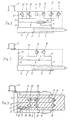
- Fig. L shows the simplest embodiment of the control circuit according to the invention.
- Fig. 2 gives the circuit at pre see further adjustable throttle bodies again.
- 3 illustrates a compact design of the control circuit according to the invention within the piston of the piston / cylinder unit.
- Fig. 4 represents a further embodiment variant, etc. in one of Fig. 2 analog throttle circuit.
- 5 finally illustrates a very simple embodiment of the control circuit according to the invention.
- a connecting line 6 leading to the other piston chamber 5 leads from the cylinder chamber 4 free of the piston rod, in which a first check valve is installed, which prevents the hydraulic fluid from flowing back from the cylinder chamber 5 into the cylinder chamber 4.
- a line 8 leads from the connecting line 6 to a compensation space 9, which serves to compensate for the different volumes of the two cylinder spaces 4 and 5.
- a further controllable throttle element 10 is provided in line 8, the throttle effect of which can be controlled by means of an adjusting screw (not shown).
- a further line 11 leading to the compensation space 9 branches off from the cylinder space 4 or from the connecting line 6, in which a further check valve 12, which closes the direct flow of the hydraulic fluid from the cylinder space 4 into the compensation space 9, is arranged.
- This further check valve can be bypassed via a bypass line 13, in which a first controllable throttle element 14 is arranged.
- the first check valve 7 is replaced by a shuttle valve 15, which is designed as a double-acting check valve.
- the connecting line 6 opens into this shuttle valve 15 at one end and leads back between the two valve seats of the shuttle valve to the other cylinder chamber.
- line 8 leads to the first controllable throttle element.
- the shuttle valve is preloaded by a spring 16 such that it has the return flow from the cylinder chamber 5 shown in the drawing in the cylinder space 4 preventing position.
- Both in the line 8 and in the bypass line 13 are parallel to the further controllable throttle element 10 or to the first controllable throttle element 14, a throttle element 17 and 18 that closes when the pressure rises, and a throttle element 19 and 20 that opens when the pressure increases further switched on.
- the throttling elements 17 and 18 further close the flow, so that the respective piston movement is counteracted more strongly. If the pressure in the line 8 or the bypass line 13 increases further, the valves 19 and 20 open, as a result of which the joints are blocked due to excessive counterpressure and thus the safety of the users is increased.
- the throttling elements 17, 18, 19, 20 can be reset to the starting position by means of a spring when the pressure conditions in the line 8 or the bypass line 13 fall back to the normal value.
- a throttle element 21 having a predetermined passage width is provided in the connecting line 6 between the cylinder chamber 4 and the cylinder chamber 5, with no check valve being arranged in this connecting line in a modification of the other exemplary embodiments. Rather, a bypass line 22 which bypasses the further adjustable throttle element 10 is provided, in which a check valve 23 is arranged, which blocks a flow of liquid from the cylinder space 5 to the compensation space 9.
- the volume of liquid required for filling the cylinder space 5 becomes dependent on the flow resistance in the throttle 21 or the opposite flow resistance of the liquid. sucked into the adjustable throttle element 14 either via the connecting line 6 or via the bypass line 22 and the check valve 23. The difference in volume between the volume of liquid displaced from the cylinder space 4 and the volume of liquid required for filling the cylinder space 5 is fed to the compensation space 9 via the line 13 and the first adjustable throttle element 14.
- throttle 21 it is achieved in any case that a certain passage of liquid from one cylinder chamber to the other cylinder chamber can pass through with a uniform damping effect, so that with differently adjusted throttle bodies 10 and 14 abrupt transitions between the control of the inward movement and the outward movement of the piston in the Cylinders and vice versa are avoided.
- a further check valve 24 is arranged directly in the connecting line 25 between the cylinder space 5 having the piston rod 3 and the compensation space 9, the further adjustable throttle element 10 in a bypass line 26 bypassing the check valve 24 is located.
- the piston 2 is pushed into the cylinder 1, that is to say moved to the left as seen in FIG. 5, the liquid displaced from the cylinder chamber 4 is fed into the compensation chamber 9 via the first adjustable throttle element 14 and the line 13 pressed as one other flow through the check valve 12 is prevented.
- the cylinder chamber 5 located on the back of the piston is filled unhindered via the line 25 and the check valve 24 which opens from the compensation chamber 9.
- the piston is pulled out of the cylinder, that is to say seen in FIG.
Abstract
Description
Die Erfindung bezieht sich auf eine Steuerschaltung für die Wirkung eines hydraulischen, durch eine Kolben/Zylindereinheit gebildeten Reglers, insbesondere für die Regelung der Bewegung künstlicher Gelenke an Menschen, bei welchem Regler die an beiden Seiten des Kolbens befindlichen Zylinderräume durch einen ein Regelorgan für den Durchfluß von der die Kolbenstange aufweisenden Kolbenseite zur gegenüberliegenden Kolbenseite aufweisenden Durchgang verbunden sind, wobei zudem beide Zylinderräume mit einem Kompensationsraum zum Ausgleich der aufgrund der Kolbenstange unterschiedlichen Volumina der Zylinderräume in Verbindung stehen, wobei in der Verbindungsleitung zwischen dem von der Kolbenstange freien Zylinderraum und dem Kompensationsraum ein das Durchströmen in Richtung zum Kompensationsraum verhinderndes weiteres Rückschlagventil vorgesehen ist, und wobei im Strömungsverlauf von dem von der Kolbenstange freien Zylinderraum zum Kompensationsraum ein erstes einstellbares Drosselorgan vorgesehen ist.The invention relates to a control circuit for the action of a hydraulic regulator formed by a piston / cylinder unit, in particular for regulating the movement of artificial joints in humans, in which regulator the cylinder spaces located on both sides of the piston are controlled by a regulating element for the flow are connected from the piston side having the piston rod to the opposite piston side having passage, both cylinder spaces also being connected to a compensation space to compensate for the different volumes of the cylinder spaces due to the piston rod, with a connection line between the cylinder space free of the piston rod and the compensation space the flow through in the direction of the compensation chamber preventing another check valve is provided, and a first adjustable throttle in the flow course from the cylinder chamber free of the piston rod to the compensation chamber organ is provided.
Bei einer bekannten Ausbildung dieser Art ist das erste einstellbare Drosselorgan im Strömungsverlauf von dem von der Kolbenstange freien Zylinderraum zum Kompensationsraum angeordnet. Dadurch kann mit diesem einstellbaren Drosselorgan lediglich die Bewegung der Kolbenstange in Richtung eines Verkürzens der Kolben/Zylindereinheit gesteuert werden, wogegen die Rückbewegung des Kolbens bestenfalls durch einen zwischen dem die Kolbenstange aufweisenden Zylinderraum und dem Kompensations raum vorgesehenen Drosselspalt gedrosselt werden kann. Keinesfalls ist jedenfalls die Rückbewegung, also das Strecken der Kolben- und Zylindereinheit geregelt steuerbar.In a known embodiment of this type, the first adjustable throttle element is arranged in the flow course from the cylinder space free of the piston rod to the compensation space. As a result, this adjustable throttle element can only be used to control the movement of the piston rod in the direction of shortening the piston / cylinder unit, whereas the return movement of the piston can at best be throttled by a throttle gap provided between the piston rod and the compensation chamber. In any case, the return movement, that is to say the stretching of the piston and cylinder unit, can in any case be controlled in a controlled manner.
Es hat sich nun gezeigt, daß insbesondere für die Regelung der Bewegung künstlicher Gelenke an Menschen es angezeigt ist, die Streckbewegung der Gelenke, also das Ausziehen der Kolben/Zylindereinheit geregelt steuern zu können, da nur dadurch ein möglichst natürlicher Bewegungsablauf der Gelenke erreicht wird.It has now been shown that, in particular for regulating the movement of artificial joints in humans, it is advisable to be able to control the stretching movement of the joints, that is to say the extension of the piston / cylinder unit, since this is the only way to achieve the most natural possible movement sequence of the joints.
Der Erfindung liegt die Aufgabe zugrunde, eine Steuerschaltung der eingangs genannten Art zu schaffen, mit welcher eine Regelung beider Bewegungsrichtungen des Kolbens im Zylinder bewirkt werden kann.The invention has for its object to provide a control circuit of the type mentioned, with which regulation of both directions of movement of the piston in the cylinder can be effected.
Erfindungsgemäß wird diese Aufgabe dadurch gelöst, daß das erste einstellbare Drosselorgan in einer, das Rückschlagventil umgehenden Bypaßleitung angeordnet ist, wobei im Strömungsverlauf von dem die Kolbenstange aufweisenden Zylinderraum zum Kompensationsraum ein weiteres einstellbares Drosselorgan angeordnet ist, wobei der die Kolbenstange aufweisende Zylinderraum über eine, ein weiteres Rückschlagventil aufweisende Leitung füllbar ist. Durch eine solche Ausbildung wird erreicht, daß man in den Verbindungsleitungen zwischen den Zylinderräumen und dem Kompensationsraum durch Anordnung von Rückschlagventilen das Auslangen findet. Diese beeinflussen die Strömung in der nicht gesperrten Richtung nicht, was eine störungsfreie Füllung des unbeaufschlagten Kolbenraumes ergibt, wobei der beaufschlagte Kolbenraum die verdrängte Flüssigkeit über das zugeordnete einstellbare Drosselorgan abführt. Es wird dabei bei einer Ausziehbewegung des Kolbens die aus dem mit der Kolbenstange versehenen Kolbenraum verdrängte Flüssigkeit über das weitere Drosselorgan in den Kompensationsraum gepreßt, wodurch durch dieses Drosselorgan die Ausziehbewegung regelbar ist. Bei der Einschubbewegung des Kolbens in den Zylinder kann die verdrängte Hydraulikflüssigkeit zur Gänze über das erste einstellbare Drosselorgan in den Kompensationsraum gepreßt werden, wobei jene Flüssigkeitsmenge, welche zur Füllung des hinter dem Kolben liegenden Zylinderraums benötigt wird, von dem Kompensationsraum direkt in diesen Kolbenraum eingebracht wird. Da jedoch bei der Rückbewegung in der Regel eine andere Regelung gewünscht wird, ist das in der Bypaßleitung vorgesehene erste einstellbare Drosselorgan so eingestellt, daß der durchströmenden Flüssigkeit ein anderer Widerstand entgegengesetzt wird als durch das weitere einstellbare Drosselorgan. Damit ist eine Ausführung erzielt, bei welcher die Hauptbewegungsrichtung die Ausziehbewegung des Kolbens aus dem Zylinder ist, und bei welcher aber auch die Einschiebebewegung des Kolbens in den Zylinder mittels eines einstellbaren Drosselorganes steuerbar ist.According to the invention, this object is achieved in that the first adjustable throttle member is arranged in a bypass line which bypasses the check valve, with another adjustable throttle member being arranged in the flow from the cylinder chamber having the piston rod to the compensation chamber, the cylinder chamber having the piston rod being connected via a Another check valve line is fillable. With such a design it is achieved that in the connecting lines between the cylinder spaces and the compensation space, by arranging check valves, it is possible to get by. These do not influence the flow in the non-blocked direction, which results in a trouble-free filling of the unloaded piston space, the loaded piston space discharging the displaced liquid via the assigned adjustable throttle element. During a pull-out movement of the piston, the liquid displaced from the piston space provided with the piston rod is pressed into the compensation space via the further throttle element, whereby the pull-out movement can be regulated by this throttle element. When the piston is pushed into the cylinder, the displaced hydraulic fluid can be pressed entirely into the compensation chamber via the first adjustable throttle element, the amount of liquid that is required to fill the cylinder chamber behind the piston being introduced directly into this piston chamber from the compensation chamber . However, since a different regulation is generally desired during the return movement, the first adjustable throttle element provided in the bypass line is set such that the liquid flowing through is opposed to a resistance different from that of the further adjustable throttle element. An embodiment is thus achieved in which the main direction of movement is the pulling-out movement of the piston out of the cylinder, and in which the insertion movement of the piston into the cylinder can also be controlled by means of an adjustable throttle element.
Vorteilhafterweise kann das weitere Rückschlagventil im Durchgang zwischen den beiden Kolbenräumen angeordnet sein. Dadurch wird erreicht, daß bei der Kolbenbewegung im Sinne des Einschiebens jener Teil der Hydraulikflüssigkeit, der zur Füllung des die Kolbenstange aufweisenden Kolbenraumes benötigt wird, direkt über den Durchgang gefördert wird. Bei einer besonders vorteilhaften Variante kann das zwischen beiden Zylinderräumen vorgesehene Rückschlagventil als Wechselventil ausgebildet sein, welches von dem von der Kolbenstange freien Zylinderraum her von der einen Seite beaufschlagt ist, von welcher Leitung die Bypaßleitung zum ersten einstellbaren Drosselorgan ausgeht, wobei von der anderen Seite des Wechselventils die zum weiteren einstellbaren Drosselorgan führende Leitung ausgeht, und wobei von der Mitte des Wechselventils die zu dem die Kolbenstange aufweisenden Zylinderraum führende Leitung ausgeht. Durch ein solches Wechselventil ist es möglich, bei der Einschubbewegung des Kolbens in den Zylinder das weitere einstellbare Drosselorgan aus dem Flüssigkeitsweg auszuschalten, sodaß die gesamte überschüssige, der Differenz des veränderten Zylinderraums entsprechende Flüssigkeitsverdrängung über das erste einstellbare Drosselorgan geführt wird, wodurch eine völlig unabhängige Steuerung der Dämpfung der Kolben/Zylindereinheit in beiden Bewegungsrichtungen des Kolbens innerhalb des Zylinders erzielt ist. Um eine noch bessere Anpassung der Regelungswirkung an Bewegungen künstlicher Gelenke zu erzielen, können zu den beiden einstellbaren Drosselorganen weitere, bei Ansteigen des Druckes schließende Drosselorgane parallelgeschaltet sein, wobei gegebenenfalls noch weitere Drosselorgane, die bei noch weiterem Ansteigen des Druckes öffnen, vorgesehen sind. Durch die bei Ansteigen des Druckes schließenden Drosselorgane wird erreicht, daß trotz Ansteigen des Druckes auf der einen Kolbenseite die Kolbenbewegung innerhalb des Zylinders nicht beschleunigt wird, sodaß bei einer aufgrund der Bewegung anderen Hebelwirkung des künstlichen Gelenks des Menschen keine schnellere Bewegung der einzelnen durch das künstliche Gelenk verbundenen Teile erfolgt. Um allerdings bei zu starkem Ansteigen des Druckes eine Zerstörung einzelner Teile der Steuerung zu vermeiden, können, wie schon angeführt, die noch weiteren Drosselorgane vorgesehen sein. In besonders vorteilhafter Ausbildung können die weiteren, bei Ansteigen des Druckes schließenden bzw. die bei noch weiterem Ansteigen des Druckes öffnenden Drosselorgane durch Federbelastung rückstellbar sein.The further check valve can advantageously be arranged in the passage between the two piston spaces. This ensures that that part of the hydraulic fluid which is used for Filling the piston chamber having the piston rod is needed, is conveyed directly through the passage. In a particularly advantageous variant, the check valve provided between the two cylinder spaces can be designed as a shuttle valve which is acted upon from one side by the cylinder space free from the piston rod, from which line the bypass line leads to the first adjustable throttle element, the other side of the Exchangeable valve, the line leading to the further adjustable throttle element goes out, and the line leading to the cylinder chamber having the piston rod extends from the center of the changeover valve. Such a shuttle valve makes it possible to switch off the further adjustable throttle element from the fluid path when the piston is inserted into the cylinder, so that the entire excess fluid displacement corresponding to the difference in the changed cylinder space is guided over the first adjustable throttle element, which means that the control is completely independent the damping of the piston / cylinder unit is achieved in both directions of movement of the piston within the cylinder. In order to achieve an even better adaptation of the regulating effect to movements of artificial joints, further throttling elements that close when the pressure rises can be connected in parallel to the two adjustable throttling elements, wherein further throttling elements that open when the pressure increases still further are optionally provided. The throttling elements that close when the pressure increases mean that, despite the increase in pressure on one side of the piston, the piston movement within the cylinder is not accelerated, so that when the lever acts differently due to the movement of the artificial joint of the human being, no faster movement of the individual through the artificial one Articulated parts are made. However, in order to avoid destruction of individual parts of the control when the pressure rises too much, as already mentioned, the further throttling elements can be provided. In a particularly advantageous embodiment, the further throttle elements that close when the pressure rises or open when the pressure rises further can be reset by spring loading.
Bei einer weiteren Ausführungsvariante kann das Regelorgan im Durchgang als Drossel ausgebildet sein, wobei das weitere einstellbare Drosselorgan durch eine Bypaßleitung umgehbar ist, in welcher ein den Durchfluß von dem die Kolbenstange aufweisenden Zylinderraum zum Kompensationsraum sperrendes Rückschlagventil angeordnet ist. Durch eine solche Ausbildung wird erreicht, daß bei ungleichmäßigen Bewegungseigenschaften bzw. Steuerungswirkungen der einstellbaren Drosselorgane fühlbar ungleichmäßige Bewegungseigenschaften ausgeschaltet werden, da über das im Durchgang eingeschaltete Drosselorgan immer ein gewisser Durchfluß von Flüssigkeit von der einen Kolbenseite zur anderen Kolbenseite gegeben ist, wobei zufolge der zwischen den Kolbenräumen und dem Kompensationsraum angeordneten Rückschlagventile eine zuverlässige Füllung des jeweils in Bewegungsrichtung des Kolbens hinten liegenden Zylinderraumes sichergestellt ist, u.zw. ohne daß in diesem Zylinderraum ein höherer Unterdruck auftritt, welcher unter Umständen zu Dampfblasenbildungen in der Flüssigkeit führen könnte.In a further embodiment variant, the control member can be designed as a throttle in the passage, the further adjustable throttle member being bypassable by a bypass line in which a check valve blocking the flow from the cylinder chamber having the piston rod to the compensation chamber is arranged. Such a design ensures that in the event of uneven movement properties or control effects of the adjustable throttling elements, noticeably uneven movement properties are switched off, since a certain flow of liquid from one side of the piston to the other side of the piston is always given via the throttle element switched on in the passageway, the intermediate between the piston chambers and the compensation chamber arranged check valves a reliable filling of the cylinder chamber located in the direction of movement of the piston is ensured, etc. without a higher negative pressure occurring in this cylinder space, which could possibly lead to vapor bubble formation in the liquid.
Bei einer weiteren Ausführungsvariante kann das weitere Rückschlagventil direkt in der Verbindungsleitung zwischen dem die Kolbenstange aufweisenden Zylinderraum und dem Kompensationsraum angeordnet sein, wobei das weitere einstellbare Drosselorgan in einer das Rückschlagventil umgehenden Bypaßleitung liegt. Dadurch wird erreicht, daß die gesamte verdrängte Flüssigkeit über jeweils ein einstellbares Drosselorgan und die zur Füllung des unbeaufschlagten Kolbenraumes benötigte Flüssigkeit direkt aus dem Kompensationsraum angesaugt wird, wodurch verhindert ist, daß in dem unbeaufschlagten Kolbenraum bzw. in der vorgeschalteten Leitung ein Unterdruck entsteht, welcher die Füllung unangenehm beeinflussen könnte. Weiters ist vermieden, daß die Befüllung des jeweils unbeaufschlagten Kolbenraumes über irgendwelche Drosselorgane erfolgt, die gleichfalls z.B. durch Wirbelbildung die Befüllung stören könnten.In a further embodiment variant, the further check valve can be arranged directly in the connecting line between the cylinder chamber having the piston rod and the compensation chamber, the further adjustable throttle element being in a bypass line bypassing the check valve. This ensures that the entire displaced liquid is sucked in directly from the compensation chamber via an adjustable throttle element and the liquid required to fill the unpressurized piston chamber, thereby preventing a negative pressure from developing in the unloaded piston chamber or in the upstream line could affect the filling unpleasantly. Furthermore, it is avoided that the filling of the unpressurized piston chamber takes place via any throttle elements, which also e.g. could disturb the filling due to vortex formation.
In der Zeichnung sind verschiedene Ausführungsformen der Steuerschaltung in Form schematischer Schaltbilder wiedergegeben. Fig. l zeigt die einfachste Ausgestaltung der erfindungsgemäßen Steuerschaltung. Fig. 2 gibt die Schaltung bei vorge sehenen weiteren einstellbaren Drosselorganen wieder. Fig. 3 veranschaulicht eine kompakte Bauform der erfindungsgemäßen Steuerschaltung innerhalb des Kolbens der Kolben/Zylindereinheit. Fig.4 stellt eine weitere Ausführungsvariante dar u.zw. bei einer der Fig. 2 analogen Drosselorganschaltung. Fig. 5 veranschaulicht schließlich eine sehr einfache Ausführungsform der erfindungsgemäßen Steuerschaltung.Various embodiments of the control circuit are shown in the drawing in the form of schematic circuit diagrams. Fig. L shows the simplest embodiment of the control circuit according to the invention. Fig. 2 gives the circuit at pre see further adjustable throttle bodies again. 3 illustrates a compact design of the control circuit according to the invention within the piston of the piston / cylinder unit. Fig. 4 represents a further embodiment variant, etc. in one of Fig. 2 analog throttle circuit. 5 finally illustrates a very simple embodiment of the control circuit according to the invention.
Mit 1 ist ein Zylinder bezeichnet, in welchem ein Kolben 2 mittels einer Kolbenstange 3 in axialer Richtung verschiebbar ist. Mit 4 ist der von der Kolbenstange freie Zylinderraum bezeichnet und mit 5 der durch die Kolbenstange verkleinerte Zylinderraum. Von dem von der Kolbenstange freien Zylinderraum 4 führt eine zum anderen Kolbenraum 5 führende Verbindungsleitung 6 weg, in welcher ein erstes Rückschlagventil eingebaut ist, welches ein Rückfließen der Hydraulikflüssigkeit vom Zylinderraum 5 in den Zylinderraum 4 verhindert. Von der Verbindungsleitung 6 führt eine Leitung 8 zu einem Kompensationsraum 9, welcher zum Ausgleich der unterschiedlichen Volumina der beiden Zylinderräume 4 und 5 dient. In der Leitung 8 ist ein weiteres regelbares Drosselorgan 10 vorgesehen, dessen Drosselwirkung mittels einer nicht dargestellten Einstellschraube steuerbar ist.1 denotes a cylinder in which a
Vom Zylinderraum 4 bzw. von der Verbindungsleitung 6 zweigt eine weitere zum Kompensationsraum 9 führende Leitung 11 ab, in welcher ein weiteres Rückschlagventil 12, welches den direkten Fluß der Hydraulikflüssigkeit vom Zylinderraum 4 in den Kompensationsraum 9 abschließt, angeordnet ist. Dieses weitere Rückschlagventil ist über eine Bypaßleitung 13 umgehbar, in welcher ein erstes regelbares Drosselorgan 14 angeordnet ist.A
Bei den Ausführungsbeispielen gemäß Fig. 2 und 3 ist das erste Rückschlagventil 7 durch ein Wechselventil 15 ersetzt, welches als doppelt wirkendes Rückschlagventil ausgebildet ist. In dieses Wechselventil 15 mündet die Verbindungsleitung 6 an dem einen Ende ein, und führt zwischen den beiden Ventilsitzen des Wechselventils zum anderen Zylinderraum zurück. Am anderen Ende des Wechselventils führt die Leitung 8 zum ersten regelbaren Drosselorgan weg. Das Wechselventil ist dabei durch eine Feder 16 derart vorbelastet, daß es die in der Zeichnung wiedergegebene, den Rückfluß vom Zylinderraum 5 in den Zylinderraum 4 verhindernde Stellung einnimmt.In the exemplary embodiments according to FIGS. 2 and 3, the
Sowohl in der Leitung 8 als auch in der Bypaßleitung 13 sind parallel zum weiteren regelbaren Drosselorgan 10 bzw. zum ersten regelbaren Drosselorgan 14 je ein bei Ansteigen des Druckes schließendes Drosselorgan 17 und 18 sowie je ein bei noch weiterem Ansteigen des Druckes öffnendes Drosselorgan 19 und 20 eingeschaltet.Both in the
Wird der Kolben 2 über die Kolbenstange 3 im Zylinder 1 in Richtung eines Herausbewegens des Kolbens aus dem Zylinder, also in den Fig. nach rechts, bewegt, dann wird die im Zylinderraum 5 befindliche Hydraulikflüssigkeit über einen Teil der Verbindungsleitung 6, die Leitung 8 und das weitere regelbare Drosselorgan 10 zum Kompensationsraum 9 gedrängt. Gleichzeitig wird aus dem Kompensationsraum 9 über die Leitung 11, das Rückschlagventil 12 und bei den Fig. 1 und 2 auch noch über einen Teil der Verbindungsleitung 6 Hydraulikflüssigkeit aus dem Kompensationsraum in den Zylinderraum 4 eingesaugt. Da in der Leitung 11 keinerlei Drosselung erfolgt, erfolgt die gesamte Regelung in dieser Bewegungsrichtung über das weitere regelbare Drosselorgan 10.If the
Wird nun der Kolben 2 in entgegengesetzter Richtung im Zylinder 1 bewegt, also in den Fig. 1 - 3 nach links, dann wird die im Zylinderraum 4 befindliche Hydraulikflüssigkeit über die Verbindungsleitung 6 und das Rückschlagventil 7 zum einen Teil in den Zylinderraum 5 geleitet, wobei gemäß Fig. l das dem Differenzvolumen zwischen den beiden Zylinderräumen entsprechende Flüssigkeitsvolumen über die Leitung 8 und das einstellbare Drosselorgan 10 in den Kompensationsraum 9 geleitet wird. Ist das erste einstellbare Drosselorgan 14 in der Bypaßleitung 13 so eingestellt, daß es dem Fluß der Hydraulikflüssigkeit einen geringeren Widerstand entgegensetzt als das weitere regelbare Drosselorgan, dann wird das dem Differenzvolumen entsprechende Flüssigkeitsvolumen über die Bypaßleitung 13 und das erste regelbare Drosselorgan in den Kompensationsraum 9 gelangen.If the
Bei der Ausführungsform gemäß den Fig. 2 und 3 ist aufgrund des Wechselventils 15, welches bei dieser Kolbenbewegung eine Stellung einnimmt, daß das Abschlußorgan des Wechselventils das Eintreten von Hydraulikflüssigkeit in die Leitung 8 verhindert, das weitere regelbare Drosselorgan 10 vom Durchfluß der Hydraulikflüssigkeit ausgeschaltet. Es wird damit das gesamte dem Differenzvolumen entsprechende Flüssigkeitsvolumen über die Bypaßleitung 13 und das erste regelbare Drosselorgan 14 geleitet, wodurch eine völlig unabhängige Regelung in beiden Kolbenbewegungsrichtungen erreicht ist.In the embodiment according to FIGS. 2 and 3, due to the
Übersteigt bei den Ausführungsformen nach den Fig. 2 und 3 der in der Leitung 8 bzw. in der Bypaßleitung 13 herrschende Druck einen vorgegebenen Wert, dann schließen die Drosselorgane 17 bzw. 18 den Durchfluß weiter, sodaß der jeweiligen Kolbenbewegung stärker entgegengewirkt wird. Bei weiterem Ansteigen des Druckes in der Leitung 8 bzw. der Bypaßleitung 13 öffnen die Ventile l9 und 20, wodurch einem Blockieren der Gelenke durch zu hohen Gegendruck und damit die Sicherheit der Benützer erhöht wird. Die Drosselorgane 17, 18,19, 20 sind dabei mittels einer Feder in die Ausgangsstellung rückstellbar, wenn die Druckverhältnisse in der Leitung 8 bzw. der Bypaßleitung 13 wieder auf den Normalwert zurückfallen.If, in the embodiments according to FIGS. 2 and 3, the pressure prevailing in the
Beim Ausführungsbeispiel nach Fig. 4 ist in der Verbindungsleitung 6 zwischen dem Zylinderraum 4 und dem Zylinderraum 5 ein, eine vorgegebene Durchgangsweite aufweisendes Drosselorgan 21 vorgesehen, wobei in dieser Verbindungsleitung in Abwandlung der übrigen Ausführungsbeispiele kein Rückschlagventil angeordnet ist. Vielmehr ist eine das weitere einstellbare Drosselorgan 10 umgehende Bypaßleitung 22 vorgesehen, in welcher ein Rückschlagventil 23 angeordnet ist, welches einen Durchfluß von Flüssigkeit vom Zylinderraum 5 zum Kompensationsraum 9 sperrt.In the exemplary embodiment according to FIG. 4, a
Wird der Kolben 2 im Zylinder 1 im Sinne eines Verlängerns der Kolben/Zylindereinheit, also in Fig. 1 nach rechts, bewegt, dann wird die aus dem Zylinderraum 5 verdrängte Flüssigkeit dann, wenn der Durchströmwiderstand in der Drossel 21 höher ist als in dem einstellbaren Regelventil, über das Drosselorgan 10 zum Kompensationsraum 9 geführt. In den Zylinderraum 4 wird aus dem Kompensationsraum Flüssigkeit über das sich öffnende Rückschlagventil 12 und die Leitung 11 bzw. einen Teil der Leitung 6 eingesaugt. Es erfolgt damit also die Dämpfung der Bewegung durch das einstellbare Drosselorgan 10. Ist hin gegen der Durchströmwiderstand im weiteren einstellbaren Drosselorgan 10 höher als in der Drossel 21, dann wird die aus dem Zylinderraum 5 verdrängte Flüssigkeit über die Verbindungsleitung 6 und die Drossel 21 in den Zylinderraum 4 gepreßt, sodaß aus dem Kompensationsraum 9 über die Leitung 11 und das Rückschlagventil 12 lediglich das Differenzvolumen der zur Füllung des Zylinderraumes 4 benötigten Flüssigkeit angesaugt wird.If the
Wird nun der Kolben 2 im Sinne eines Einschiebens in den Zylinder 1, also in Fig. 4 gesehen nach links, bewegt, dann wird das für die Füllung des Zylinderraumes 5 benötigte Flüssigkeitsvolumen in Abhängigkeit vom dem der Flüssigkeit entgengesetzten Durchströmwiderstand in der Drossel 21 bzw. im einstellbaren Drosselorgan l4 entweder über die Verbindungsleitung 6 oder über die Bypaßleitung 22 und das Rückschlagventil 23 angesaugt. Das Differenzvolumen zwischen dem aus dem Zylinderraum 4 verdrängten Flüssigkeitsvolumen und dem für die Füllung des Zylinderraumes 5 benötigten Flüssigkeitsvolumen wird über die Leitung 13 und das erste einstellbare Drosselorgan 14 dem Kompensationsraum 9 zugeführt. Durch die Drossel 21 wird auf jeden Fall erreicht, daß ein gewisser Flüssigkeitsdurchtritt von einem Zylinderraum zum anderen Zylinderraum mit einer gleichförmigen Dämpfungswirkung durchtreten kann, sodaß bei unterschiedlich stark eingestellten Drosselorganen 10 bzw. 14 abrupte Übergänge zwischen der Steuerung der Einwärtsbewegung und der Auswärtsbewegung des Kolbens im Zylinder und umgekehrt vermieden sind.If the
Bei der in Fig. 5 wiedergegebenen Ausführungsvariante handelt es sich um eine besonders einfache Form, bei welcher ein weiteres Rückschlagventil 24 direkt in der Verbindungsleitung 25 zwischen dem die Kolbenstange 3 aufweisenden Zylinderraum 5 und dem Kompensationsraum 9 angeordnet ist, wobei das weitere einstellbare Drosselorgan 10 in einer das Rückschlagventil 24 umgehenden Bypaßleitung 26 liegt.5 is a particularly simple form in which a
Wird bei der Ausführungsform nach Fig. 5 der Kolben 2 in den Zylinder 1 hineingeschoben, also in Fig. 5 gesehen nach links bewegt, dann wird die aus dem Zylinderraum 4 verdrängte Flüssigkeit über das erste einstellbare Drosselorgan 14 und die Leitung 13 in den Kompensationsraum 9 gepreßt, da ein anderer Strömungsverlauf durch das Rückschlagventil 12 unterbunden ist. Das Befüllen des an der Rückseite des Kolbens liegenden Zylinderraumes 5 erfolgt unbehindert über die Leitung 25 und das sich öffnende Rückschlagventil 24 aus dem Kompensationsraum 9. Wird bei dem in Fig. 5 wiedergegebenen Ausführungsbeispiel der Kolben aus dem Zylinder herausgezogen, also in Fig. 5 gesehen nach rechts, bewegt, dann wird die aus dem Zylinderraum 5 verdrängte Hydraulikflüssigkeit über das weitere einstellbare Drosselorgan 10 und die Leitungen 26 und 13 in den Kompensationsraum 9 gefördert, wobei die Füllung des Zylinderraumes 4 über die das Rückschlagventil 12 aufweisende Leitung erfolgt, wobei gleichfalls in dieser Leitung außer dem Rückschlagventil kein anderes Regelventil angeordnet ist, welches gegebenenfalls eine Füllung des Zylinderraumes nachteilig beeinflussen könnte.If, in the embodiment according to FIG. 5, the
Claims (7)
Applications Claiming Priority (2)
| Application Number | Priority Date | Filing Date | Title |
|---|---|---|---|
| AT2864/87 | 1987-10-30 | ||
| AT0286487A AT391801B (en) | 1987-10-30 | 1987-10-30 | HYDRAULIC CONTROL |
Publications (3)
| Publication Number | Publication Date |
|---|---|
| EP0314668A2 true EP0314668A2 (en) | 1989-05-03 |
| EP0314668A3 EP0314668A3 (en) | 1990-02-14 |
| EP0314668B1 EP0314668B1 (en) | 1993-08-25 |
Family
ID=3541521
Family Applications (1)
| Application Number | Title | Priority Date | Filing Date |
|---|---|---|---|
| EP88890270A Expired - Lifetime EP0314668B1 (en) | 1987-10-30 | 1988-10-28 | Hydraulic control |
Country Status (7)
| Country | Link |
|---|---|
| US (1) | US4958705A (en) |
| EP (1) | EP0314668B1 (en) |
| JP (1) | JP2736080B2 (en) |
| AT (2) | AT391801B (en) |
| CA (1) | CA1332099C (en) |
| DE (1) | DE3883481D1 (en) |
| ES (1) | ES2045192T3 (en) |
Cited By (5)
| Publication number | Priority date | Publication date | Assignee | Title |
|---|---|---|---|---|
| EP0728451A1 (en) * | 1995-02-24 | 1996-08-28 | Otto Bock Orthopädische Industrie Besitz- und Verwaltungs-Kommanditgesellschaft | Braked knee joint |
| FR2771624A1 (en) * | 1996-05-17 | 1999-06-04 | Joseph L Molino | Knee unit for an above-knee prosthetic leg |
| CN103846904A (en) * | 2012-11-30 | 2014-06-11 | 中国科学院沈阳自动化研究所 | Servo valve box for controlling underwater hydraulic manipulator |
| CN110561406A (en) * | 2019-08-31 | 2019-12-13 | 华南理工大学 | Bionic person-oriented artificial muscle bidirectional driving mechanism |
| CN115898990A (en) * | 2023-01-05 | 2023-04-04 | 中国人民解放军国防科技大学 | Bionic joint driving hydraulic system |
Families Citing this family (29)
| Publication number | Priority date | Publication date | Assignee | Title |
|---|---|---|---|---|
| US5103811A (en) * | 1990-07-09 | 1992-04-14 | Crupi Jr Theodore P | Body part or joint brace |
| FR2735018B1 (en) * | 1995-06-09 | 1997-07-11 | Proteval | PNEUMATIC PROSTHETIC PART FOR THE KNEE JOINT |
| JP3829264B2 (en) * | 1996-03-19 | 2006-10-04 | 株式会社日立製作所 | Damping force adjustable hydraulic shock absorber |
| US5800561A (en) * | 1996-05-15 | 1998-09-01 | Massachusetts Institute Of Technology | Power-assisted upper extremity orthosis |
| US6113642A (en) | 1996-06-27 | 2000-09-05 | Mauch, Inc. | Computer controlled hydraulic resistance device for a prosthesis and other apparatus |
| CN1237949C (en) | 2000-01-20 | 2006-01-25 | 麻省理工学院 | Electronically controlled prosthetic knee |
| WO2001072245A2 (en) | 2000-03-29 | 2001-10-04 | Massachusetts Institute Of Technology | Speed-adaptive and patient-adaptive prosthetic knee |
| US6464048B1 (en) * | 2000-07-24 | 2002-10-15 | Tenneco Automotive Inc. | Solenoid actuated continuously variable shock absorber |
| US6666127B2 (en) | 2002-05-03 | 2003-12-23 | Muscle Tech Ltd. | Artificial muscle |
| US7736394B2 (en) | 2002-08-22 | 2010-06-15 | Victhom Human Bionics Inc. | Actuated prosthesis for amputees |
| AU2003236750B2 (en) | 2002-08-22 | 2006-08-10 | Victhom Human Bionics Inc. | Actuated leg prosthesis for above-knee amputees |
| US7198071B2 (en) | 2003-05-02 | 2007-04-03 | Össur Engineering, Inc. | Systems and methods of loading fluid in a prosthetic knee |
| US7815689B2 (en) | 2003-11-18 | 2010-10-19 | Victhom Human Bionics Inc. | Instrumented prosthetic foot |
| US20050107889A1 (en) | 2003-11-18 | 2005-05-19 | Stephane Bedard | Instrumented prosthetic foot |
| US7438164B2 (en) * | 2003-12-08 | 2008-10-21 | Tenneco Automotive Operating Company Inc. | Solenoid actuated continuously variable servo valve for adjusting damping in shock absorbers and struts |
| US7637959B2 (en) | 2004-02-12 | 2009-12-29 | össur hf | Systems and methods for adjusting the angle of a prosthetic ankle based on a measured surface angle |
| US20050283257A1 (en) * | 2004-03-10 | 2005-12-22 | Bisbee Charles R Iii | Control system and method for a prosthetic knee |
| EP1734909B1 (en) | 2004-03-10 | 2013-06-12 | Össur hf | Control system for a prosthetic knee |
| US7455696B2 (en) | 2004-05-07 | 2008-11-25 | össur hf | Dynamic seals for a prosthetic knee |
| DE102004031562A1 (en) * | 2004-06-29 | 2006-02-16 | Otto Bock Healthcare Ip Gmbh & Co. Kg | Artificial foot |
| GB2420395A (en) * | 2004-11-18 | 2006-05-24 | Westland Helicopters | Vibration damping apparatus for a helicopter rotor system |
| CA2863933C (en) | 2004-12-22 | 2018-08-07 | Ossur Hf | Systems and methods for processing limb motion |
| US8801802B2 (en) | 2005-02-16 | 2014-08-12 | össur hf | System and method for data communication with a mechatronic device |
| SE528516C2 (en) | 2005-04-19 | 2006-12-05 | Lisa Gramnaes | Combined active and passive leg prosthesis system and a method for performing a movement cycle with such a system |
| CN101453964B (en) | 2005-09-01 | 2013-06-12 | 奥瑟Hf公司 | System and method for determining terrain transitions |
| US10842653B2 (en) | 2007-09-19 | 2020-11-24 | Ability Dynamics, Llc | Vacuum system for a prosthetic foot |
| EP2257247B1 (en) | 2008-03-24 | 2018-04-25 | Ossur HF | Transfemoral prosthetic systems and methods for operating the same |
| TR201816406T4 (en) | 2013-02-26 | 2018-11-21 | Oessur Hf | Prosthetic foot with improved stability and flexible energy return. |
| GB2588116B (en) * | 2019-10-07 | 2022-02-23 | Caterpillar Global Mining Llc | Method and apparatus for operating a machine work tool |
Citations (5)
| Publication number | Priority date | Publication date | Assignee | Title |
|---|---|---|---|---|
| US2859451A (en) * | 1956-11-05 | 1958-11-11 | Hans A Mauch | Hydraulic system |
| WO1984001605A1 (en) * | 1982-10-20 | 1984-04-26 | Donald Maxwell Culley | A vibration damper |
| DE8708011U1 (en) * | 1987-06-05 | 1987-08-27 | Aros Hydraulik Gmbh, 8940 Memmingen, De | |
| EP0237085A1 (en) * | 1986-01-30 | 1987-09-16 | Peters, Willem | Hydraulic shock damper assembly for use in vehicles |
| GB2194309A (en) * | 1986-08-19 | 1988-03-02 | Wilson Sporting Goods | Hydraulic valve assembly for controlling a hydraulic cylinder |
Family Cites Families (5)
| Publication number | Priority date | Publication date | Assignee | Title |
|---|---|---|---|---|
| US4051558A (en) * | 1976-06-30 | 1977-10-04 | The United States Of America As Represented By The United States National Aeronautics And Space Administration | Mechanical energy storage device for hip disarticulation |
| US4266639A (en) * | 1979-05-10 | 1981-05-12 | International Telephone And Telegraph Corporation | Quick response hydraulic shock suppressor for piping systems |
| FR2531175B1 (en) * | 1982-07-27 | 1986-04-04 | Bennes Marrel | PILOT VALVE FOR BRAKING OR SPEED LIMITATION IN A HYDRAULIC CIRCUIT |
| SE458945B (en) * | 1985-02-18 | 1989-05-22 | Vaexjoe Protes Ab | HYDRAULIC DEVICE, SPECIFICALLY FOR LEG PROTECTION |
| JPS6234809A (en) * | 1985-08-06 | 1987-02-14 | Kayaba Ind Co Ltd | Hydraulic shock absorber |
-
1987
- 1987-10-30 AT AT0286487A patent/AT391801B/en not_active IP Right Cessation
-
1988
- 1988-10-28 DE DE88890270T patent/DE3883481D1/en not_active Expired - Fee Related
- 1988-10-28 EP EP88890270A patent/EP0314668B1/en not_active Expired - Lifetime
- 1988-10-28 AT AT88890270T patent/ATE93595T1/en not_active IP Right Cessation
- 1988-10-28 US US07/264,213 patent/US4958705A/en not_active Expired - Lifetime
- 1988-10-28 ES ES88890270T patent/ES2045192T3/en not_active Expired - Lifetime
- 1988-10-28 CA CA000581672A patent/CA1332099C/en not_active Expired - Fee Related
- 1988-10-31 JP JP63273399A patent/JP2736080B2/en not_active Expired - Lifetime
Patent Citations (5)
| Publication number | Priority date | Publication date | Assignee | Title |
|---|---|---|---|---|
| US2859451A (en) * | 1956-11-05 | 1958-11-11 | Hans A Mauch | Hydraulic system |
| WO1984001605A1 (en) * | 1982-10-20 | 1984-04-26 | Donald Maxwell Culley | A vibration damper |
| EP0237085A1 (en) * | 1986-01-30 | 1987-09-16 | Peters, Willem | Hydraulic shock damper assembly for use in vehicles |
| GB2194309A (en) * | 1986-08-19 | 1988-03-02 | Wilson Sporting Goods | Hydraulic valve assembly for controlling a hydraulic cylinder |
| DE8708011U1 (en) * | 1987-06-05 | 1987-08-27 | Aros Hydraulik Gmbh, 8940 Memmingen, De |
Cited By (7)
| Publication number | Priority date | Publication date | Assignee | Title |
|---|---|---|---|---|
| EP0728451A1 (en) * | 1995-02-24 | 1996-08-28 | Otto Bock Orthopädische Industrie Besitz- und Verwaltungs-Kommanditgesellschaft | Braked knee joint |
| FR2771624A1 (en) * | 1996-05-17 | 1999-06-04 | Joseph L Molino | Knee unit for an above-knee prosthetic leg |
| CN103846904A (en) * | 2012-11-30 | 2014-06-11 | 中国科学院沈阳自动化研究所 | Servo valve box for controlling underwater hydraulic manipulator |
| CN110561406A (en) * | 2019-08-31 | 2019-12-13 | 华南理工大学 | Bionic person-oriented artificial muscle bidirectional driving mechanism |
| CN110561406B (en) * | 2019-08-31 | 2022-10-25 | 华南理工大学 | Bionic person-oriented artificial muscle bidirectional driving mechanism |
| CN115898990A (en) * | 2023-01-05 | 2023-04-04 | 中国人民解放军国防科技大学 | Bionic joint driving hydraulic system |
| CN115898990B (en) * | 2023-01-05 | 2023-05-23 | 中国人民解放军国防科技大学 | Bionic joint driving hydraulic system |
Also Published As
| Publication number | Publication date |
|---|---|
| EP0314668A3 (en) | 1990-02-14 |
| DE3883481D1 (en) | 1993-09-30 |
| EP0314668B1 (en) | 1993-08-25 |
| ATE93595T1 (en) | 1993-09-15 |
| CA1332099C (en) | 1994-09-27 |
| JPH01160549A (en) | 1989-06-23 |
| JP2736080B2 (en) | 1998-04-02 |
| US4958705A (en) | 1990-09-25 |
| ES2045192T3 (en) | 1994-01-16 |
| ATA286487A (en) | 1990-06-15 |
| AT391801B (en) | 1990-12-10 |
Similar Documents
| Publication | Publication Date | Title |
|---|---|---|
| AT391801B (en) | HYDRAULIC CONTROL | |
| DE3201546C2 (en) | Device for controlling a hydraulic motor | |
| EP0126291B1 (en) | Fluid pressure-controlled valve | |
| EP0016719B1 (en) | Hydraulic motor control device | |
| DE1430724C3 (en) | Steering system for an articulated vehicle | |
| DE1173751B (en) | Control device for preferably several hydraulic drives supplied by one pump | |
| DE1951429C3 (en) | Hydraulic control system, especially for multiple hydraulic motors | |
| DE2364413C2 (en) | Accumulator loading valve | |
| DE3511637C2 (en) | ||
| DE3420674A1 (en) | PRESSURE SUPPLY DEVICE FOR A HYDRAULIC SYSTEM | |
| CH668814A5 (en) | PRE-CONTROLLED PRESSURE LIMIT VALVE. | |
| DE2537957A1 (en) | TAX OR CONTROL ARRANGEMENT FOR PUMPS WITH VARIABLE DISPLACEMENT | |
| DE2356414A1 (en) | Flow divider for pressure medium from pump - has control valve with double-acting piston control ducts double valve and changeover valve | |
| DE2854593A1 (en) | Hydraulic circuit with variable pump and hydraulic motor - has pump output controlled by pressure in pump and motor for multi way valve actuation | |
| DE2151837C2 (en) | Hydraulic control device for load-independent flow regulation to a consumer | |
| DE2655812A1 (en) | HYDRAULIC CONTROL CIRCUIT WITH A PUMP THAT CAN BE CHANGED IN ITS FLOW RATE | |
| DE1773415B2 (en) | PRESSURE REGULATING VALVE FOR HYDRAULIC LIQUIDS | |
| EP0170815B1 (en) | Hydraulic control device | |
| DE4406318A1 (en) | Control device for a hydraulic pump | |
| DE1803922A1 (en) | Hydraulic transfer device | |
| DE2357148A1 (en) | HYDRAULIC CIRCUIT ARRANGEMENT | |
| DE3221160A1 (en) | Control valve arrangement consisting of two control blocks for several hydraulic drives, in particular of mobile machines | |
| DE3817658C2 (en) | Valve arrangement for a hydraulic system | |
| DE1108996B (en) | Control for pressure medium consumer | |
| DE10341356B4 (en) | Bias valve with at least two switching stages and hydraulic actuator assembly |
Legal Events
| Date | Code | Title | Description |
|---|---|---|---|
| PUAI | Public reference made under article 153(3) epc to a published international application that has entered the european phase |
Free format text: ORIGINAL CODE: 0009012 |
|
| AK | Designated contracting states |
Kind code of ref document: A2 Designated state(s): AT BE CH DE ES FR GB IT LI LU NL SE |
|
| PUAL | Search report despatched |
Free format text: ORIGINAL CODE: 0009013 |
|
| AK | Designated contracting states |
Kind code of ref document: A3 Designated state(s): AT BE CH DE ES FR GB IT LI LU NL SE |
|
| RHK1 | Main classification (correction) |
Ipc: F16F 9/44 |
|
| 17P | Request for examination filed |
Effective date: 19900717 |
|
| 17Q | First examination report despatched |
Effective date: 19920217 |
|
| 17Q | First examination report despatched |
Effective date: 19921117 |
|
| GRAA | (expected) grant |
Free format text: ORIGINAL CODE: 0009210 |
|
| AK | Designated contracting states |
Kind code of ref document: B1 Designated state(s): AT BE CH DE ES FR GB IT LI LU NL SE |
|
| REF | Corresponds to: |
Ref document number: 93595 Country of ref document: AT Date of ref document: 19930915 Kind code of ref document: T |
|
| REF | Corresponds to: |
Ref document number: 3883481 Country of ref document: DE Date of ref document: 19930930 |
|
| ITF | It: translation for a ep patent filed |
Owner name: ING. A. GIAMBROCONO & C |
|
| EPTA | Lu: last paid annual fee | ||
| ET | Fr: translation filed | ||
| GBT | Gb: translation of ep patent filed (gb section 77(6)(a)/1977) |
Effective date: 19931126 |
|
| REG | Reference to a national code |
Ref country code: ES Ref legal event code: FG2A Ref document number: 2045192 Country of ref document: ES Kind code of ref document: T3 |
|
| PLBE | No opposition filed within time limit |
Free format text: ORIGINAL CODE: 0009261 |
|
| STAA | Information on the status of an ep patent application or granted ep patent |
Free format text: STATUS: NO OPPOSITION FILED WITHIN TIME LIMIT |
|
| 26N | No opposition filed | ||
| EAL | Se: european patent in force in sweden |
Ref document number: 88890270.7 |
|
| PGFP | Annual fee paid to national office [announced via postgrant information from national office to epo] |
Ref country code: LU Payment date: 19951001 Year of fee payment: 8 |
|
| PGFP | Annual fee paid to national office [announced via postgrant information from national office to epo] |
Ref country code: BE Payment date: 19951027 Year of fee payment: 8 |
|
| PG25 | Lapsed in a contracting state [announced via postgrant information from national office to epo] |
Ref country code: LU Free format text: LAPSE BECAUSE OF NON-PAYMENT OF DUE FEES Effective date: 19961028 |
|
| PG25 | Lapsed in a contracting state [announced via postgrant information from national office to epo] |
Ref country code: BE Effective date: 19961031 |
|
| BERE | Be: lapsed |
Owner name: OTTO BOCK ORTHOPADISCHE INDUSTRIE BESITZ- UND VER Effective date: 19961031 |
|
| PGFP | Annual fee paid to national office [announced via postgrant information from national office to epo] |
Ref country code: ES Payment date: 20010828 Year of fee payment: 14 |
|
| PGFP | Annual fee paid to national office [announced via postgrant information from national office to epo] |
Ref country code: FR Payment date: 20010831 Year of fee payment: 14 |
|
| PGFP | Annual fee paid to national office [announced via postgrant information from national office to epo] |
Ref country code: SE Payment date: 20010911 Year of fee payment: 14 |
|
| PGFP | Annual fee paid to national office [announced via postgrant information from national office to epo] |
Ref country code: AT Payment date: 20011030 Year of fee payment: 14 |
|
| PGFP | Annual fee paid to national office [announced via postgrant information from national office to epo] |
Ref country code: NL Payment date: 20011031 Year of fee payment: 14 Ref country code: GB Payment date: 20011031 Year of fee payment: 14 |
|
| PGFP | Annual fee paid to national office [announced via postgrant information from national office to epo] |
Ref country code: DE Payment date: 20011130 Year of fee payment: 14 |
|
| REG | Reference to a national code |
Ref country code: GB Ref legal event code: IF02 |
|
| PGFP | Annual fee paid to national office [announced via postgrant information from national office to epo] |
Ref country code: CH Payment date: 20020109 Year of fee payment: 14 |
|
| PG25 | Lapsed in a contracting state [announced via postgrant information from national office to epo] |
Ref country code: GB Free format text: LAPSE BECAUSE OF NON-PAYMENT OF DUE FEES Effective date: 20021028 Ref country code: AT Free format text: LAPSE BECAUSE OF NON-PAYMENT OF DUE FEES Effective date: 20021028 |
|
| PG25 | Lapsed in a contracting state [announced via postgrant information from national office to epo] |
Ref country code: SE Free format text: LAPSE BECAUSE OF NON-PAYMENT OF DUE FEES Effective date: 20021029 Ref country code: ES Free format text: LAPSE BECAUSE OF NON-PAYMENT OF DUE FEES Effective date: 20021029 |
|
| PG25 | Lapsed in a contracting state [announced via postgrant information from national office to epo] |
Ref country code: LI Free format text: LAPSE BECAUSE OF NON-PAYMENT OF DUE FEES Effective date: 20021031 Ref country code: CH Free format text: LAPSE BECAUSE OF NON-PAYMENT OF DUE FEES Effective date: 20021031 |
|
| PG25 | Lapsed in a contracting state [announced via postgrant information from national office to epo] |
Ref country code: NL Free format text: LAPSE BECAUSE OF NON-PAYMENT OF DUE FEES Effective date: 20030501 Ref country code: DE Free format text: LAPSE BECAUSE OF NON-PAYMENT OF DUE FEES Effective date: 20030501 |
|
| EUG | Se: european patent has lapsed | ||
| REG | Reference to a national code |
Ref country code: CH Ref legal event code: PL |
|
| GBPC | Gb: european patent ceased through non-payment of renewal fee | ||
| PG25 | Lapsed in a contracting state [announced via postgrant information from national office to epo] |
Ref country code: FR Free format text: LAPSE BECAUSE OF NON-PAYMENT OF DUE FEES Effective date: 20030630 |
|
| NLV4 | Nl: lapsed or anulled due to non-payment of the annual fee |
Effective date: 20030501 |
|
| REG | Reference to a national code |
Ref country code: FR Ref legal event code: ST |
|
| REG | Reference to a national code |
Ref country code: ES Ref legal event code: FD2A Effective date: 20031112 |
|
| PG25 | Lapsed in a contracting state [announced via postgrant information from national office to epo] |
Ref country code: IT Free format text: LAPSE BECAUSE OF NON-PAYMENT OF DUE FEES Effective date: 20051028 |