EP0314654A1 - Method and apparatus for transmitting data to the surface from an oil well - Google Patents
Method and apparatus for transmitting data to the surface from an oil well Download PDFInfo
- Publication number
- EP0314654A1 EP0314654A1 EP88850358A EP88850358A EP0314654A1 EP 0314654 A1 EP0314654 A1 EP 0314654A1 EP 88850358 A EP88850358 A EP 88850358A EP 88850358 A EP88850358 A EP 88850358A EP 0314654 A1 EP0314654 A1 EP 0314654A1
- Authority
- EP
- European Patent Office
- Prior art keywords
- transmitter
- casing
- receiver
- oil well
- signals
- Prior art date
- Legal status (The legal status is an assumption and is not a legal conclusion. Google has not performed a legal analysis and makes no representation as to the accuracy of the status listed.)
- Granted
Links
Images


Classifications
-
- E—FIXED CONSTRUCTIONS
- E21—EARTH DRILLING; MINING
- E21B—EARTH DRILLING, e.g. DEEP DRILLING; OBTAINING OIL, GAS, WATER, SOLUBLE OR MELTABLE MATERIALS OR A SLURRY OF MINERALS FROM WELLS
- E21B47/00—Survey of boreholes or wells
- E21B47/12—Means for transmitting measuring-signals or control signals from the well to the surface, or from the surface to the well, e.g. for logging while drilling
- E21B47/13—Means for transmitting measuring-signals or control signals from the well to the surface, or from the surface to the well, e.g. for logging while drilling by electromagnetic energy, e.g. radio frequency
Definitions
- the present invention relates to a method for transmitting data to the surface from a level in an oil well and an apparatus for carrying out the method, all according to the preamble of the claims.
- the present invention provides a method and an apparatus overcoming the above mentioned problem, i.e. transferring data from a level in an oil well to the surface. This is obtained by a method and an apparatus according to the present invention, as defined by the features indicated in the charac terizing clauses of the claims.
- the present invention is based on the use of casings as a line of transmission.
- the principle is based on the fact that a tubular electrical conductor through a homogenous continuous medium with a specific conductivity, will have a specific resistance, internal inductivity and conductivity in relation to the environments.
- the conductor is the central conductor in a coaxial transmission line, the characteristic impedance and attenuation can be calculated.
- the receiver is alined to the impedance of the transmission line. Depending of the configuration of the well and thus the impedance at the point of the receiver, it is possible to measure current or voltage and the corresponding alignement of the input stage of the receiver.
- the attenuation of the signal along the line is greatly dependent of the spesific resistivity of the materials being arranged close to the conductor.
- the quality of the cement used for a casting of the casing in the drill bore is therefore of great importance to the attenuation.
- Natural electromagnetic noise occurs partly from atmospheric discharges and partly from powerfull electric ionic currents in higher strata. Statistically, this noise increases with decreasing frequency. Particularly, this is the fact at the sea bed since the suppression of noise through sea water clearly increases with the frequency. However, the attenuation of the signals along the transmission line also will increase with the frequency. This is particularly the fact when the casing passes through rocks having low resistivity. For this reason, there will normally exist relatively much noise in the frequency range which conveniently is used for transmission of signals, namely 1-20Hz. For the same reason, it may be advantageously to employ the most advanced method for cancelling noise.
- the invention is based upon the fact that an uninsolated well casing which is surrounded by more or less conductive rocks can be considered as a not ideal signal wire transmission line for transmitting signals. On this basis, equipment for transmitters and receivers has been developed for minimizing the energy consumption in connection with each transferred signal.
- the invention is further based on optimum impedance adaptation between the transmitter, the receiver and the casing based on the characteristic impedance of the casing at the point of connection. Further, it is achieved with the apparatus according to the invention, maximum suppression of geoelectromagnetic noise to the receiver by means of geometrical and adaptive cancelling of the noise area vector. Additionally, the apparatus is based on bi-phase modulation and correlation detection of the signal based on synchronous transmission and reception as well as phase-locking based on maximum correlation for the entire received signal.
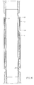
- Fig. 1 schematically discloses a sectional view through a producing well with a riser attach to a (not shown) over-laying platform
- Fig. 2 discloses a corresponding view through a sub sea producing well
- Fig. 3 discloses a temporarily abandoned well
- Fig. 4 discloses a corresponding view through a permanently abandoned well
- Fig. 5 discloses a sectional view through a permanently abandoned well with the transmitter and the receiver according to the invention
- Fig. 6 discloses a sectional view in part of the transmitter of the apparatus
- Fig. 7 discloses a block diagram for the transmitter
- Fig. 8 discloses a sectional view in part of the receiver of the apparatus
- Fig. 1 schematically discloses a sectional view through a producing well with a riser attach to a (not shown) over-laying platform
- Fig. 2 discloses a corresponding view through a sub sea producing well
- Fig. 3 discloses a temporarily abandoned well
- Fig. 10 discloses a block diagram of the receiver
- Fig. 11-14 discloses schematically various alternatives for connecting the transmitter to the casing
- Fig. 15 discloses in sectional view and schmatically the structure of a connection means for insulating the casing
- Fig. 16 discloses a modified structure of the connection means.
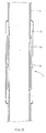
- Fig. 1 discloses schematically a producing well with riser attachment to a overlaying platform (not shown). The well is drilled but not complemented with oil pipes.
- a transmitter 1 is in the well connected to the casing 6 by means of connectors 10 and 11.
- a receiver 2 is connected to a current detector 4, laying on the sea bed 3 and surrounding the well head.
- information carrying signals, transmitted from the transmitter 1, are further transmitted to the surface, such as to a production platform, by means of conventional signal transmission, such as acoustic transmission or cable transmission.
- Fig. 2 discloses a corresponding well completed without riser.
- the transmitter 1 on one side is attached to the oil pipe and via the sealing of the oil pipe is connected to the casing 6.
- Fig. 3 discloses a temporarily abandoned well.
- the transmitter 1 is suspended in a sealing 5 and connected :o to the casing 6 with its connector 11 as well as through the sealing 5.
- the casing Above the sealing 5 the casing is closed with a plug 31.
- the transmitter 2 on the sea bed 3 here also will measure the current from the casing 6 to the sea.
- Fig. 4 depicts the apparatus according to the invention used in a permanently abandoned well.
- the well head is here removed and the well is sealed along a major length.
- the receiver 2 is connected directly to the casing 6, the latter having no direct electrical connection with the sea.
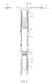
- Fig. 5 shows schematically a permanently abandoned well with the apparatus according to the invention, integrated.
- the transmitter 1 is shown more detailed in Fig. 6 and the receiver 2 is shown more detailed in Fig. 8.
- the transmitter 1 can be suspended in a sealing 5 and is connected to the casing 6 with the contacts 10 and 11, above and below a connector 12 respectively, the connector insulating an upper and lower part of the casing 6 electrically.
- the casing is permanently cast to the sea bed by cement 32.
- the cement forms an insulating layer between the casing 6 and the sea bed and contributes to reduce the transmission losses. In this connection it is essential that materials have been added to the cement, having low conductivity and thereby contributing to reduced the attenuation.
- the transmitter 2 is placed in the crater which is formed when the casing 6 is cut and pulled out and electrically connected to the casing 6 with contacts 7.
- Three sea bed electrodes 8 and a vertical electrode 9 also are connected to the transmitter 2.
- the receiver 2 measures the signal current through the casing 6 to the sea bed electrodes and compensates adaptively the received signal with basis in the noise signal to the vertical electrode 9.
- the received data from the transmitter 1 is decoded by correlation technique and stored in the receiver 2. The stored data then can be transmitted to the surface, e.g. acoustically to a vessel.
- Data is transmitted from the dowhole transmitter to the receiver on the sea bed at even intervals.
- the receiver is switched off in order to save power.
- correlation technique is used. This assumes that the receiver will "know” exactly when the signals will arrive and then will recognize alternative signal forms, represented by "0" and "1".
- two synchronously running clocks are used, one of which is located in the transmitter 1 and the other located in the receiver 2.
- the clock in the receiver is adjusted to the transmitter clock after each message, considering the deviation between the two clocks.
- the correlation algoritm is calculated from the total message being transmitted.
- Fig. 6 discloses schematically the transmitter 1 and its structure.
- the transmitter comprises a censor part 14 for measuring desired parameters such as temperature and pressure, one electronic unit 13 for the transmitting function, batteries 15 as well as contacts 10 and 11 for establishing contact between the transmitter 1 and the casing 6.
- the transmitter 1 has a neck 18 for connection of a cable during the installation of the transmitter in the well where also the cables make it possible to carry out electrical control of the transmitter after installation.
- the cable is released from the transmitter before the well is sealed by means of a seal 5 and thereafter plugged.
- the contacts 10 and 11 are electrically insulated from the transmitter which have been covered with an external insulating layer.
- the contacts 10 and 11 are forcibly pressed radially outwards after the transmitter 1 has been positioned correctly and will cut into the casing 6 above and below the connector, respectively which insulates the upper and lower parts of the casing from each other.
- the connector 12 has been formed as an extended sleeve for the casing 6 and is lowered together with the casing.
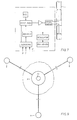
- the transmitter 1 is shown schematically in the block diagram of Fig. 7.
- Signals from the transmitter are low frequency sinusoidal currents, 1-20Hz where the data message is modulated 180° phase shift (biphase modulation).
- the drive signal for the power amplifier and the impedance transformer is digitally synthesised by means of a micro processor.
- the signal is based on an oscillator or a clock of high stability.
- the data messages from the censors are transmitted via a multiplexor and in an analogue manner to the digital converter. Digital signals are transmitted directly to the synthesizer.
- the batteries will feed the transmitter unit via power regulator which converts the prevailing battery voltage to a correct supply voltage with minimum power loss.
- the transmitter 1 can be connected to the casing 6 in two places, arranged widely apart such as shown in Fig. 11.
- the impedance between these places will be determined by the distance between the places as well as the electrical characteristics of the pipe and it's surroundings. For practical, useful distances relatively large losses will occure with this solution.
- FIG. 12 Another alternative is shown in Fig. 12 where the casing 6 has been cut between the transmitter attachment points to the casing in order to insulate an upper and lower part of the casing electrically from each other. Adequately insulated, the impedance in the attachment point will appear directly from the characteristic impedance of the casing. A practical drawback with this solution is that the casing will be lost and thus it's mechanical functions.
- the upper and lower part of the casing 6 can also be insulated by means of a connector 12.
- the connector 12 is shown schematically in Fig. 15 and is internally and externally covered with an electrically insulating material 24. This material has good cementing properties and sufficient mechanical strength to withstand the well pressure and any other tension on the casing.
- the connector 12 is attached to the casing 6 by means of an ordinary sleeve 25 while an internal steel pipe 26 is used to obtain a strong mechanical connection between the upper and lower part of the casing.
- the insulating material 24 is used to prevent a "short circuit" across the insulation gap if the formation and/or the well fluid should be strongly conductive at this point.
- the connector 12 can be made of a highly resistive material.
- Fig. 14 shows another embodiment of the invention where the connector 12 is released from the casing 6.
- the transmitter output is transferred to a toroidal wounded induction coil 27 which arranged outside the casing 6 and which axially induces a voltage in the pipe.
- the induction coil 27 in Fig. 16 is fed by the transmitter via the connection points 29, the magnetic field is established by a laminated iron core 28 surrounding the casing 6.
- the induction coil 27 and the iron core 28 is surrounded by a case 30 having a diameter like a sleeve with a tick wall.
- the advantages of the above described connector are that signal voltages are established directly in the casing 6 without having to insulate the upper and lower parts from each other. At the same time it works independently as an impedance transformer and permit transmission from the transmitter at a higher voltage level and with reduced loss.
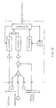
- the receiver 2 is shown in detail schematically in Fig. 8 and consists of the electronic unit 20 of the receiver which cancels noise and demodulates the signals, the battery unit 15 for the supply of energy to the receiver and for transmitting the information by means of the acoustic transmitter 22 and its aerial 23.
- the receiver is connected to the casing 6 by means of the contacts 7 which forcibly are pressed into the casing and thus creates an interface between the receiver and the casing with little resistance.
- the signal from the casing 6 is measured in relation to a system with reference to the proportions of the electrodes 8 arranged on the sea bed and a vertical electrode 9.
- the horizontal reference electrodes 8 are lying on the sea bed in precise orientations as shown in Fig. 19, with an angular distance of 120°.
- the vertical electrode 9 is formed like a floating rope with a built in electrode and extends straight up from the receiver 2 some meters above the sea bed 3. The reference electrodes are build for reducing noise in the signal frequency band.
- signals arrive from the casing 6 and the sea bed electrodes 8.
- the three reference signals are added.
- the vector sum thereby achieved, is ideally zero and is used as a reference point for the signal from the casing 6.
- a signal also arrives from the vertical electrode 9. This is used in an adaptive filter in order to suppress the vertical component in the geoelectromagnetic noise induced in the casing.
- the signal from the casing is amplified and filtered for the noise components laying near the signal frequency. Then the signal is compared with the signal from the vertical electrode 9 and the filter II as shown in Fig. 10 and is automatically adjusted in order to minimize the difference.
- the suppressed transmitter signal is added to the noise which naturally is induced in the casing 6 and which the receiver 2 is adjusted to cancel. This results in the fact that the filtered signal into correlator will be relatively pure.
- the filtered input signal is correlated with an built in time reference signal. This is built up from an ultra stable oscillator and a synthesizer of the same type as provided for the transmitter 1.
- the reference signal is indicating to the correlator exactly when the signal from the oil well is expected to be received.
- the filter III the curve is adjusted in the same way as the signal is altered through the transmission via the casing 6.
- the correlator will both indicate how the signal pattern will look like and how much the time reference should be adjusted in order to obtain maximum correlation.
- the time reference is adjusted and likewise the reference signal is adjusted so that the curve form will be correct by all changes of the signal.
- the adjusted reference signal is used to verify if the first hypothesis of the signal pattern is correct, after which the oscillator is adjusted in such a way that the time reference will be the best possible for the next sequence to be received.
Landscapes
- Engineering & Computer Science (AREA)
- Physics & Mathematics (AREA)
- Geology (AREA)
- Mining & Mineral Resources (AREA)
- Remote Sensing (AREA)
- Life Sciences & Earth Sciences (AREA)
- Geophysics (AREA)
- Fluid Mechanics (AREA)
- Environmental & Geological Engineering (AREA)
- Electromagnetism (AREA)
- General Life Sciences & Earth Sciences (AREA)
- Geochemistry & Mineralogy (AREA)
- Arrangements For Transmission Of Measured Signals (AREA)
- Synchronisation In Digital Transmission Systems (AREA)
- Lubricants (AREA)
- Removal Of Floating Material (AREA)
- Forms Removed On Construction Sites Or Auxiliary Members Thereof (AREA)
Abstract
Description
- The present invention relates to a method for transmitting data to the surface from a level in an oil well and an apparatus for carrying out the method, all according to the preamble of the claims.
- In order to make optimum use of oil reservoars, a need exists to transmit data concerning the various characteristics of the reservoar from oil wells to the surface. It is for example desireable to be able to measure pressure and temperature in the oil well and transmit data for these.
- Today, it is customary to use cable-based test-sampling measurings and it is also known to use wire-less signal transmission from the bottom of an oil well to the surface by means of electro magnetic waves, such as shown in US 2 354 887. This system, which was used to measure characteristics of the formation during drilling, has later been developed to comprise several repeting stations along the drill string in order to obtain transmission from deeper levels. Such transmission systems have been described for example in US 2 411 696 and US 4 160 970. Such systems suppose transmission using the drill string as aerial to a surface based receiver at the base of the derrick.
- US 4 015 234, US 4 387 372 and US 4 348 676 disclose solution of various practical problems related to the connection of the transmitter to the drill string used as aerial.
- The above mentioned publications describe logging of oil wells during drilling or production. It is, however, also of interest to measure for instance pressure and temperature, not only in wells under production, but also in permanently or temporary abandoned wells. Such loggings on the other hand are normally not undertaken in abandoned sub sea wells, as there today are no independent signal transmission systems which in such a situation can transmit data to the surface in a reasonable way.
- The present invention provides a method and an apparatus overcoming the above mentioned problem, i.e. transferring data from a level in an oil well to the surface. This is obtained by a method and an apparatus according to the present invention, as defined by the features indicated in the charac terizing clauses of the claims.
- With the method and the apparatus according to the invention there is disclosed a means for wireless electro magnetic data transmission from already drilled and completed sub sea wells, regardless if they are in production, or permanently or temporarily abandoned. However. the present invention is particularly directed towards permanently abandoned wells.
- Since the power for transmitting data from an abandoned well must be supplied from build in batteries with limited capasity, great demands are made on the power consumption for each transmitted signal for the practical design of the apparatus. In due of this, the apparatus according to the invention has thus been optimized accordingly.
- The present invention is based on the use of casings as a line of transmission. The principle is based on the fact that a tubular electrical conductor through a homogenous continuous medium with a specific conductivity, will have a specific resistance, internal inductivity and conductivity in relation to the environments. Thus, if the conductor is the central conductor in a coaxial transmission line, the characteristic impedance and attenuation can be calculated.
- If this view is extended to a homogenous medium such as strata in an oil field, it is possible to obtain values for reflections in the strata interfaces and general transmission characteristics from one point to another on the pipe.
- Based on such a model, which has been varyfied experimentaly, and knowledge about the statistic frequency distribution of natural electromagnetic noise at the point of the receiver it is possible to design equipment being optimally capable of transmitting information between the points using a minimal consumption of energy. These considerations are essential for the solution of the problem conserning transmission of data from an abandoned well, namely a minimum loss of signal between the transmitter and the transmission line, optimum utilization of the signal on the line at the point of the receiver, maximum suppression of geoelectromagnetic noice to the receiver and an option of the transmission fre quency as well as a method of detection in order to obtain an optimum signal-to-noise relationship with at least a possible power output from the transmitter and in shortest possible time, thus keeping the consumption of energy at a minimum. Minimum loss of signal is obtained by adapting the impedance between the transmitter and the characteristic impedance of the transmission line. The receiver is alined to the impedance of the transmission line. Depending of the configuration of the well and thus the impedance at the point of the receiver, it is possible to measure current or voltage and the corresponding alignement of the input stage of the receiver.
- The attenuation of the signal along the line is greatly dependent of the spesific resistivity of the materials being arranged close to the conductor. The quality of the cement used for a casting of the casing in the drill bore is therefore of great importance to the attenuation.
- Natural electromagnetic noise occurs partly from atmospheric discharges and partly from powerfull electric ionic currents in higher strata. Statistically, this noise increases with decreasing frequency. Particularly, this is the fact at the sea bed since the suppression of noise through sea water clearly increases with the frequency. However, the attenuation of the signals along the transmission line also will increase with the frequency. This is particularly the fact when the casing passes through rocks having low resistivity. For this reason, there will normally exist relatively much noise in the frequency range which conveniently is used for transmission of signals, namely 1-20Hz. For the same reason, it may be advantageously to employ the most advanced method for cancelling noise.
- The invention is based upon the fact that an uninsolated well casing which is surrounded by more or less conductive rocks can be considered as a not ideal signal wire transmission line for transmitting signals. On this basis, equipment for transmitters and receivers has been developed for minimizing the energy consumption in connection with each transferred signal.
- The invention is further based on optimum impedance adaptation between the transmitter, the receiver and the casing based on the characteristic impedance of the casing at the point of connection. Further, it is achieved with the apparatus according to the invention, maximum suppression of geoelectromagnetic noise to the receiver by means of geometrical and adaptive cancelling of the noise area vector. Additionally, the apparatus is based on bi-phase modulation and correlation detection of the signal based on synchronous transmission and reception as well as phase-locking based on maximum correlation for the entire received signal.
- In the drawing, Fig. 1, schematically discloses a sectional view through a producing well with a riser attach to a (not shown) over-laying platform, Fig. 2 discloses a corresponding view through a sub sea producing well, Fig. 3 discloses a temporarily abandoned well, Fig. 4 discloses a corresponding view through a permanently abandoned well, Fig. 5 discloses a sectional view through a permanently abandoned well with the transmitter and the receiver according to the invention, Fig. 6 discloses a sectional view in part of the transmitter of the apparatus, Fig. 7 discloses a block diagram for the transmitter, Fig. 8 discloses a sectional view in part of the receiver of the apparatus, Fig. 9 discloses a general view of the location of reference electrodes on the sea bed, Fig. 10 discloses a block diagram of the receiver, Fig. 11-14 discloses schematically various alternatives for connecting the transmitter to the casing, Fig. 15 discloses in sectional view and schmatically the structure of a connection means for insulating the casing, and Fig. 16 discloses a modified structure of the connection means. Fig. 1 discloses schematically a producing well with riser attachment to a overlaying platform (not shown). The well is drilled but not complemented with oil pipes. A
transmitter 1 is in the well connected to thecasing 6 by means ofconnectors receiver 2 is connected to acurrent detector 4, laying on thesea bed 3 and surrounding the well head. - From the
receiver 2, information carrying signals, transmitted from thetransmitter 1, are further transmitted to the surface, such as to a production platform, by means of conventional signal transmission, such as acoustic transmission or cable transmission. - Fig. 2 discloses a corresponding well completed without riser. The
transmitter 1 on one side is attached to the oil pipe and via the sealing of the oil pipe is connected to thecasing 6. - Fig. 3 discloses a temporarily abandoned well. Here, the
transmitter 1 is suspended in a sealing 5 and connected :o to thecasing 6 with itsconnector 11 as well as through the sealing 5. Above the sealing 5 the casing is closed with aplug 31. Provided the well head has adequate electrical contact with the sea water, thetransmitter 2 on thesea bed 3 here also will measure the current from thecasing 6 to the sea. - Fig. 4 depicts the apparatus according to the invention used in a permanently abandoned well. The well head is here removed and the well is sealed along a major length. The
receiver 2 is connected directly to thecasing 6, the latter having no direct electrical connection with the sea. - Fig. 5 shows schematically a permanently abandoned well with the apparatus according to the invention, integrated. The
transmitter 1 is shown more detailed in Fig. 6 and thereceiver 2 is shown more detailed in Fig. 8. Thetransmitter 1 can be suspended in a sealing 5 and is connected to thecasing 6 with thecontacts connector 12 respectively, the connector insulating an upper and lower part of thecasing 6 electrically. The casing is permanently cast to the sea bed bycement 32. The cement forms an insulating layer between thecasing 6 and the sea bed and contributes to reduce the transmission losses. In this connection it is essential that materials have been added to the cement, having low conductivity and thereby contributing to reduced the attenuation. - The
transmitter 2 is placed in the crater which is formed when thecasing 6 is cut and pulled out and electrically connected to thecasing 6 withcontacts 7. Threesea bed electrodes 8 and avertical electrode 9 also are connected to thetransmitter 2. Thereceiver 2 measures the signal current through thecasing 6 to the sea bed electrodes and compensates adaptively the received signal with basis in the noise signal to thevertical electrode 9. The received data from thetransmitter 1 is decoded by correlation technique and stored in thereceiver 2. The stored data then can be transmitted to the surface, e.g. acoustically to a vessel. - Data is transmitted from the dowhole transmitter to the receiver on the sea bed at even intervals. In the time between the signals which can last some seconds, the receiver is switched off in order to save power. In order to detect the signals which are hidden in noise having about the same frequences, correlation technique is used. This assumes that the receiver will "know" exactly when the signals will arrive and then will recognize alternative signal forms, represented by "0" and "1". In order to achieve this, two synchronously running clocks are used, one of which is located in the
transmitter 1 and the other located in thereceiver 2. The clock in the receiver is adjusted to the transmitter clock after each message, considering the deviation between the two clocks. The correlation algoritm is calculated from the total message being transmitted. - By using the detection principle a traditional phase locked loop is avoided and thus the need for separate energy consuming synchronization sequences before starting the data transmission.
- Fig. 6 discloses schematically the
transmitter 1 and its structure. The transmitter comprises acensor part 14 for measuring desired parameters such as temperature and pressure, oneelectronic unit 13 for the transmitting function,batteries 15 as well ascontacts transmitter 1 and thecasing 6. Further, thetransmitter 1 has aneck 18 for connection of a cable during the installation of the transmitter in the well where also the cables make it possible to carry out electrical control of the transmitter after installation. The cable is released from the transmitter before the well is sealed by means of aseal 5 and thereafter plugged. - The
contacts contacts transmitter 1 has been positioned correctly and will cut into thecasing 6 above and below the connector, respectively which insulates the upper and lower parts of the casing from each other. Theconnector 12 has been formed as an extended sleeve for thecasing 6 and is lowered together with the casing. - Electrically, the
transmitter 1 is shown schematically in the block diagram of Fig. 7. Signals from the transmitter are low frequency sinusoidal currents, 1-20Hz where the data message is modulated 180° phase shift (biphase modulation). The drive signal for the power amplifier and the impedance transformer is digitally synthesised by means of a micro processor. The signal is based on an oscillator or a clock of high stability. The data messages from the censors are transmitted via a multiplexor and in an analogue manner to the digital converter. Digital signals are transmitted directly to the synthesizer. - The batteries will feed the transmitter unit via power regulator which converts the prevailing battery voltage to a correct supply voltage with minimum power loss.
- For effective transmission of the signal power from the
transmitter 1 to thecasing 6 there is a need for aconnector 12 so that small changes of the "line impedance" occure from the transmitter into thecasing 6. For this purpose thetransmitter 1 can be connected to thecasing 6 in two places, arranged widely apart such as shown in Fig. 11. The impedance between these places will be determined by the distance between the places as well as the electrical characteristics of the pipe and it's surroundings. For practical, useful distances relatively large losses will occure with this solution. - Another alternative is shown in Fig. 12 where the
casing 6 has been cut between the transmitter attachment points to the casing in order to insulate an upper and lower part of the casing electrically from each other. Adequately insulated, the impedance in the attachment point will appear directly from the characteristic impedance of the casing. A practical drawback with this solution is that the casing will be lost and thus it's mechanical functions. - As shown in Fig. 13 the upper and lower part of the
casing 6 can also be insulated by means of aconnector 12. With such a solution the transmitter will work towards a transmission line having an impedance which is determined by the electrical characteristics of the casing and the surrounding formation. Theconnector 12 is shown schematically in Fig. 15 and is internally and externally covered with an electrically insulatingmaterial 24. This material has good cementing properties and sufficient mechanical strength to withstand the well pressure and any other tension on the casing. Theconnector 12 is attached to thecasing 6 by means of anordinary sleeve 25 while aninternal steel pipe 26 is used to obtain a strong mechanical connection between the upper and lower part of the casing. The insulatingmaterial 24 is used to prevent a "short circuit" across the insulation gap if the formation and/or the well fluid should be strongly conductive at this point. Alternatively theconnector 12 can be made of a highly resistive material. - Fig. 14 shows another embodiment of the invention where the
connector 12 is released from thecasing 6. Here the transmitter output is transferred to a toroidal woundedinduction coil 27 which arranged outside thecasing 6 and which axially induces a voltage in the pipe. Theinduction coil 27 in Fig. 16 is fed by the transmitter via the connection points 29, the magnetic field is established by alaminated iron core 28 surrounding thecasing 6. Theinduction coil 27 and theiron core 28 is surrounded by acase 30 having a diameter like a sleeve with a tick wall. - The advantages of the above described connector are that signal voltages are established directly in the
casing 6 without having to insulate the upper and lower parts from each other. At the same time it works independently as an impedance transformer and permit transmission from the transmitter at a higher voltage level and with reduced loss. Thereceiver 2 is shown in detail schematically in Fig. 8 and consists of theelectronic unit 20 of the receiver which cancels noise and demodulates the signals, thebattery unit 15 for the supply of energy to the receiver and for transmitting the information by means of theacoustic transmitter 22 and its aerial 23. The receiver is connected to thecasing 6 by means of thecontacts 7 which forcibly are pressed into the casing and thus creates an interface between the receiver and the casing with little resistance. - The signal from the
casing 6 is measured in relation to a system with reference to the proportions of theelectrodes 8 arranged on the sea bed and avertical electrode 9. Thehorizontal reference electrodes 8 are lying on the sea bed in precise orientations as shown in Fig. 19, with an angular distance of 120°. Thevertical electrode 9 is formed like a floating rope with a built in electrode and extends straight up from thereceiver 2 some meters above thesea bed 3. The reference electrodes are build for reducing noise in the signal frequency band. - To the
receiver 2 signals arrive from thecasing 6 and thesea bed electrodes 8. The three reference signals are added. The vector sum thereby achieved, is ideally zero and is used as a reference point for the signal from thecasing 6. To the receiver 2 a signal also arrives from thevertical electrode 9. This is used in an adaptive filter in order to suppress the vertical component in the geoelectromagnetic noise induced in the casing. The signal from the casing is amplified and filtered for the noise components laying near the signal frequency. Then the signal is compared with the signal from thevertical electrode 9 and the filter II as shown in Fig. 10 and is automatically adjusted in order to minimize the difference. - When the
transmitter 1 in the oil well is started, the suppressed transmitter signal is added to the noise which naturally is induced in thecasing 6 and which thereceiver 2 is adjusted to cancel. This results in the fact that the filtered signal into correlator will be relatively pure. - In the
receiver 2 the filtered input signal is correlated with an built in time reference signal. This is built up from an ultra stable oscillator and a synthesizer of the same type as provided for thetransmitter 1. The reference signal is indicating to the correlator exactly when the signal from the oil well is expected to be received. By means of the filter III the curve is adjusted in the same way as the signal is altered through the transmission via thecasing 6. When the signal from the oil well is received, the correlator will both indicate how the signal pattern will look like and how much the time reference should be adjusted in order to obtain maximum correlation. - The time reference is adjusted and likewise the reference signal is adjusted so that the curve form will be correct by all changes of the signal. The adjusted reference signal is used to verify if the first hypothesis of the signal pattern is correct, after which the oscillator is adjusted in such a way that the time reference will be the best possible for the next sequence to be received.
Claims (7)
Applications Claiming Priority (2)
| Application Number | Priority Date | Filing Date | Title |
|---|---|---|---|
| NO874428A NO163578C (en) | 1987-10-23 | 1987-10-23 | PROCEDURE AND DEVICE FOR TRANSFER OF TARGET DATA FROM A OIL BROWN TO THE SURFACE. |
| NO874428 | 1987-10-23 |
Publications (2)
| Publication Number | Publication Date |
|---|---|
| EP0314654A1 true EP0314654A1 (en) | 1989-05-03 |
| EP0314654B1 EP0314654B1 (en) | 1992-01-08 |
Family
ID=19890334
Family Applications (1)
| Application Number | Title | Priority Date | Filing Date |
|---|---|---|---|
| EP88850358A Expired - Lifetime EP0314654B1 (en) | 1987-10-23 | 1988-10-21 | Method and apparatus for transmitting data to the surface from an oil well |
Country Status (3)
| Country | Link |
|---|---|
| EP (1) | EP0314654B1 (en) |
| ES (1) | ES2029077T3 (en) |
| NO (1) | NO163578C (en) |
Cited By (27)
| Publication number | Priority date | Publication date | Assignee | Title |
|---|---|---|---|---|
| GB2259832B (en) * | 1991-09-12 | 1996-04-10 | Geoservices | Method and apparatus for transmitting information between equipment at the bottom of a drilling or production operation and the surface |
| GB2317797A (en) * | 1996-09-26 | 1998-04-01 | British Gas Plc | Pipeline Communication System |
| EP0927812A2 (en) * | 1997-12-29 | 1999-07-07 | Halliburton Energy Services, Inc. | Electromagnetic signal repeater |
| EP0932054A2 (en) * | 1998-01-27 | 1999-07-28 | Halliburton Energy Services, Inc. | Downhole telemetry system and method for remote communication |
| WO2002014907A1 (en) * | 2000-08-15 | 2002-02-21 | Baker Hughes Incorporated | Apparatus and method for synchronized formation measurement |
| EP1473256A1 (en) * | 2003-04-30 | 2004-11-03 | Gaz De France | Method and apparatus for data transmission between surface and an underground salt cavity |
| EP0922836B1 (en) * | 1997-12-10 | 2006-03-29 | Halliburton Energy Services, Inc. | Subsea repeater and method for use of the same |
| WO2006059079A1 (en) * | 2004-12-03 | 2006-06-08 | Expro North Sea Limited | Downhole communication |
| WO2008031021A2 (en) | 2006-09-08 | 2008-03-13 | Chevron U.S.A., Inc. | A telemetry apparatus and method for monitoring a borehole |
| WO2009038474A1 (en) * | 2007-09-20 | 2009-03-26 | Ziebel As | A method of abandoning a petroleum well |
| US7636052B2 (en) | 2007-12-21 | 2009-12-22 | Chevron U.S.A. Inc. | Apparatus and method for monitoring acoustic energy in a borehole |
| US7810993B2 (en) | 2007-02-06 | 2010-10-12 | Chevron U.S.A. Inc. | Temperature sensor having a rotational response to the environment |
| US7841234B2 (en) | 2007-07-30 | 2010-11-30 | Chevron U.S.A. Inc. | System and method for sensing pressure using an inductive element |
| US7863907B2 (en) | 2007-02-06 | 2011-01-04 | Chevron U.S.A. Inc. | Temperature and pressure transducer |
| US8106791B2 (en) | 2007-04-13 | 2012-01-31 | Chevron U.S.A. Inc. | System and method for receiving and decoding electromagnetic transmissions within a well |
| US8353677B2 (en) | 2009-10-05 | 2013-01-15 | Chevron U.S.A. Inc. | System and method for sensing a liquid level |
| CN101410728B (en) * | 2006-03-31 | 2013-07-10 | 雪佛龙美国公司 | Method and apparatus for sensing a borehole characteristic |
| US8575936B2 (en) | 2009-11-30 | 2013-11-05 | Chevron U.S.A. Inc. | Packer fluid and system and method for remote sensing |
| US9547104B2 (en) | 2007-09-04 | 2017-01-17 | Chevron U.S.A. Inc. | Downhole sensor interrogation employing coaxial cable |
| GB2552557A (en) * | 2016-10-25 | 2018-01-31 | Expro North Sea Ltd | Communication systems and methods |
| US20180252100A1 (en) * | 2015-12-11 | 2018-09-06 | Halliburton Energy Services, Inc. | Subsurface electric field monitoring methods and systems employing a current focusing cement arrangement |
| WO2018178607A1 (en) * | 2017-03-31 | 2018-10-04 | Metrol Technology Ltd | Monitoring well installations |
| WO2018178606A1 (en) * | 2017-03-31 | 2018-10-04 | Metrol Technology Ltd | Monitoring well installations |
| US10100634B2 (en) | 2015-09-18 | 2018-10-16 | Baker Hughes, A Ge Company, Llc | Devices and methods to communicate information from below a surface cement plug in a plugged or abandoned well |
| US10488286B2 (en) | 2009-11-30 | 2019-11-26 | Chevron U.S.A. Inc. | System and method for measurement incorporating a crystal oscillator |
| US20210131274A1 (en) * | 2018-03-29 | 2021-05-06 | Metrol Technology Ltd | Downhole communication |
| US11448062B2 (en) | 2018-03-28 | 2022-09-20 | Metrol Technology Ltd. | Well installations |
Families Citing this family (2)
| Publication number | Priority date | Publication date | Assignee | Title |
|---|---|---|---|---|
| DK1393136T3 (en) | 2001-04-26 | 2009-05-11 | Abb As | Method for monitoring and detecting sensor failures in oil and gas production systems |
| WO2018236352A1 (en) * | 2017-06-20 | 2018-12-27 | Halliburton Energy Services, Inc. | Methods and systems with downhole synchronization based on a direct digital synthesizer (dds) |
Citations (4)
| Publication number | Priority date | Publication date | Assignee | Title |
|---|---|---|---|---|
| US3905010A (en) * | 1973-10-16 | 1975-09-09 | Basic Sciences Inc | Well bottom hole status system |
| GB1557863A (en) * | 1976-06-22 | 1979-12-12 | Shell Int Research | Method and means for transmitting information through a pipe string situated in a borehole oe well |
| US4569598A (en) * | 1984-07-03 | 1986-02-11 | Jacobs Donald H | Radio synchronized clock |
| WO1986003545A1 (en) * | 1984-12-04 | 1986-06-19 | Saga Petroleum A.S. | Method for remote registration of down hole parameters |
-
1987
- 1987-10-23 NO NO874428A patent/NO163578C/en not_active IP Right Cessation
-
1988
- 1988-10-21 EP EP88850358A patent/EP0314654B1/en not_active Expired - Lifetime
- 1988-10-21 ES ES198888850358T patent/ES2029077T3/en not_active Expired - Lifetime
Patent Citations (4)
| Publication number | Priority date | Publication date | Assignee | Title |
|---|---|---|---|---|
| US3905010A (en) * | 1973-10-16 | 1975-09-09 | Basic Sciences Inc | Well bottom hole status system |
| GB1557863A (en) * | 1976-06-22 | 1979-12-12 | Shell Int Research | Method and means for transmitting information through a pipe string situated in a borehole oe well |
| US4569598A (en) * | 1984-07-03 | 1986-02-11 | Jacobs Donald H | Radio synchronized clock |
| WO1986003545A1 (en) * | 1984-12-04 | 1986-06-19 | Saga Petroleum A.S. | Method for remote registration of down hole parameters |
Cited By (52)
| Publication number | Priority date | Publication date | Assignee | Title |
|---|---|---|---|---|
| GB2259832B (en) * | 1991-09-12 | 1996-04-10 | Geoservices | Method and apparatus for transmitting information between equipment at the bottom of a drilling or production operation and the surface |
| GB2317797B (en) * | 1996-09-26 | 2001-07-25 | British Gas Plc | Pipeline communication system |
| GB2317797A (en) * | 1996-09-26 | 1998-04-01 | British Gas Plc | Pipeline Communication System |
| EP0922836B1 (en) * | 1997-12-10 | 2006-03-29 | Halliburton Energy Services, Inc. | Subsea repeater and method for use of the same |
| EP0927812A2 (en) * | 1997-12-29 | 1999-07-07 | Halliburton Energy Services, Inc. | Electromagnetic signal repeater |
| EP0927812A3 (en) * | 1997-12-29 | 2001-06-27 | Halliburton Energy Services, Inc. | Electromagnetic signal repeater |
| EP0932054A2 (en) * | 1998-01-27 | 1999-07-28 | Halliburton Energy Services, Inc. | Downhole telemetry system and method for remote communication |
| EP0932054A3 (en) * | 1998-01-27 | 2000-06-14 | Halliburton Energy Services, Inc. | Downhole telemetry system and method for remote communication |
| WO2002014907A1 (en) * | 2000-08-15 | 2002-02-21 | Baker Hughes Incorporated | Apparatus and method for synchronized formation measurement |
| EP1473256A1 (en) * | 2003-04-30 | 2004-11-03 | Gaz De France | Method and apparatus for data transmission between surface and an underground salt cavity |
| FR2854425A1 (en) * | 2003-04-30 | 2004-11-05 | Gaz De France | METHOD AND DEVICE FOR TRANSMITTING INFORMATION BETWEEN A SALINE CAVITY AND THE SOIL SURFACE |
| US7151465B2 (en) | 2003-04-30 | 2006-12-19 | Gaz De France | Method and apparatus for transmitting information between a salt-cavern and the surface of the ground |
| WO2006059079A1 (en) * | 2004-12-03 | 2006-06-08 | Expro North Sea Limited | Downhole communication |
| US8164475B2 (en) | 2004-12-03 | 2012-04-24 | Expro North Sea Limited | Downhole communication |
| CN101410728B (en) * | 2006-03-31 | 2013-07-10 | 雪佛龙美国公司 | Method and apparatus for sensing a borehole characteristic |
| CN101529276B (en) * | 2006-09-08 | 2013-03-20 | 雪佛龙美国公司 | A telemetry apparatus and method for monitoring a borehole |
| US8390471B2 (en) | 2006-09-08 | 2013-03-05 | Chevron U.S.A., Inc. | Telemetry apparatus and method for monitoring a borehole |
| AU2007292254B2 (en) * | 2006-09-08 | 2013-09-26 | Chevron U.S.A., Inc. | A telemetry apparatus and method for monitoring a borehole |
| WO2008031021A2 (en) | 2006-09-08 | 2008-03-13 | Chevron U.S.A., Inc. | A telemetry apparatus and method for monitoring a borehole |
| WO2008031021A3 (en) * | 2006-09-08 | 2009-05-14 | Chevron Usa Inc | A telemetry apparatus and method for monitoring a borehole |
| US7810993B2 (en) | 2007-02-06 | 2010-10-12 | Chevron U.S.A. Inc. | Temperature sensor having a rotational response to the environment |
| US7863907B2 (en) | 2007-02-06 | 2011-01-04 | Chevron U.S.A. Inc. | Temperature and pressure transducer |
| US8083405B2 (en) | 2007-02-06 | 2011-12-27 | Chevron U.S.A. Inc. | Pressure sensor having a rotational response to the environment |
| US8143906B2 (en) | 2007-02-06 | 2012-03-27 | Chevron U.S.A. Inc. | Temperature and pressure transducer |
| US8106791B2 (en) | 2007-04-13 | 2012-01-31 | Chevron U.S.A. Inc. | System and method for receiving and decoding electromagnetic transmissions within a well |
| US8261607B2 (en) | 2007-07-30 | 2012-09-11 | Chevron U.S.A. Inc. | System and method for sensing pressure using an inductive element |
| US7841234B2 (en) | 2007-07-30 | 2010-11-30 | Chevron U.S.A. Inc. | System and method for sensing pressure using an inductive element |
| US9547104B2 (en) | 2007-09-04 | 2017-01-17 | Chevron U.S.A. Inc. | Downhole sensor interrogation employing coaxial cable |
| WO2009038474A1 (en) * | 2007-09-20 | 2009-03-26 | Ziebel As | A method of abandoning a petroleum well |
| US7636052B2 (en) | 2007-12-21 | 2009-12-22 | Chevron U.S.A. Inc. | Apparatus and method for monitoring acoustic energy in a borehole |
| US8353677B2 (en) | 2009-10-05 | 2013-01-15 | Chevron U.S.A. Inc. | System and method for sensing a liquid level |
| US8784068B2 (en) | 2009-10-05 | 2014-07-22 | Chevron U.S.A. Inc. | System and method for sensing a liquid level |
| US8575936B2 (en) | 2009-11-30 | 2013-11-05 | Chevron U.S.A. Inc. | Packer fluid and system and method for remote sensing |
| US10488286B2 (en) | 2009-11-30 | 2019-11-26 | Chevron U.S.A. Inc. | System and method for measurement incorporating a crystal oscillator |
| US10100634B2 (en) | 2015-09-18 | 2018-10-16 | Baker Hughes, A Ge Company, Llc | Devices and methods to communicate information from below a surface cement plug in a plugged or abandoned well |
| GB2559501B (en) * | 2015-09-18 | 2021-07-21 | Baker Hughes A Ge Co Llc | Devices and methods to communicate information from below a surface cement plug in a plugged or abandoned well |
| US20180252100A1 (en) * | 2015-12-11 | 2018-09-06 | Halliburton Energy Services, Inc. | Subsurface electric field monitoring methods and systems employing a current focusing cement arrangement |
| GB2552557B (en) * | 2016-10-25 | 2018-08-29 | Expro North Sea Ltd | Communication systems and methods |
| GB2552557A (en) * | 2016-10-25 | 2018-01-31 | Expro North Sea Ltd | Communication systems and methods |
| US10683748B2 (en) | 2016-10-25 | 2020-06-16 | Expro Meters, Inc. | Communication systems and methods |
| WO2018178607A1 (en) * | 2017-03-31 | 2018-10-04 | Metrol Technology Ltd | Monitoring well installations |
| WO2018178688A1 (en) * | 2017-03-31 | 2018-10-04 | Metrol Technology Ltd | Powering downhole devices |
| US10858932B2 (en) | 2017-03-31 | 2020-12-08 | Metrol Technology Ltd | Monitoring well installations |
| WO2018178606A1 (en) * | 2017-03-31 | 2018-10-04 | Metrol Technology Ltd | Monitoring well installations |
| US11085272B2 (en) | 2017-03-31 | 2021-08-10 | Metrol Technology Ltd. | Powering downhole devices |
| US11156062B2 (en) | 2017-03-31 | 2021-10-26 | Metrol Technology Ltd. | Monitoring well installations |
| EP4151831A1 (en) * | 2017-03-31 | 2023-03-22 | Metrol Technology Ltd | Powering downhole devices |
| EP4151832A1 (en) * | 2017-03-31 | 2023-03-22 | Metrol Technology Ltd | Monitoring well installations |
| AU2017407833B2 (en) * | 2017-03-31 | 2023-09-21 | Metrol Technology Ltd | Monitoring well installations |
| US11448062B2 (en) | 2018-03-28 | 2022-09-20 | Metrol Technology Ltd. | Well installations |
| US20210131274A1 (en) * | 2018-03-29 | 2021-05-06 | Metrol Technology Ltd | Downhole communication |
| US11674385B2 (en) * | 2018-03-29 | 2023-06-13 | Metrol Technology Ltd. | Downhole communication |
Also Published As
| Publication number | Publication date |
|---|---|
| NO874428L (en) | 1989-04-24 |
| NO874428D0 (en) | 1987-10-23 |
| NO163578B (en) | 1990-03-12 |
| EP0314654B1 (en) | 1992-01-08 |
| NO163578C (en) | 1990-06-20 |
| ES2029077T3 (en) | 1992-07-16 |
Similar Documents
| Publication | Publication Date | Title |
|---|---|---|
| EP0314654A1 (en) | Method and apparatus for transmitting data to the surface from an oil well | |
| EP0922836B1 (en) | Subsea repeater and method for use of the same | |
| US7482945B2 (en) | Apparatus for interfacing with a transmission path | |
| US4057781A (en) | Well bore communication method | |
| AU766351B2 (en) | Multilateral well and electrical transmission system | |
| CA1264811A (en) | Well data transmission system using a magnetic drill string for transmitting data as a magnetic flux signal | |
| US5235285A (en) | Well logging apparatus having toroidal induction antenna for measuring, while drilling, resistivity of earth formations | |
| AU2009351112B2 (en) | Method and system of transmitting acoustic signal from a wellbore | |
| US4087781A (en) | Electromagnetic lithosphere telemetry system | |
| US5959548A (en) | Electromagnetic signal pickup device | |
| CN109899059B (en) | Drill string communication systems, components, and methods | |
| AU2201783A (en) | Apparatus and method for logging wells while drilling | |
| NO319695B1 (en) | Electromagnetic signal amplifier device and method for communicating information between equipment immersed in a wellbore and equipment on the surface | |
| GB2360532A (en) | System and method for communicating with a downhole tool using electromagnetic telemetry and a fixed downhole receiver | |
| WO2002012676A1 (en) | Apparatus and method for telemetry | |
| EP1451445A1 (en) | A device and a method for electrical coupling | |
| MX2013005021A (en) | System and method for remote sensing. | |
| US7071837B2 (en) | Data transmission in pipeline systems | |
| GB2346509A (en) | Borehole communication system | |
| CA1205376A (en) | Apparatus for, and a method of, signalling within a borehole while drilling | |
| EP0913708A2 (en) | Electromagnetic signal pickup apparatus and method for use of same | |
| JP2003504543A (en) | Data transmission in pipeline systems | |
| GB2364724A (en) | System and method for communicating with a downhole tool using electromagnetic telemetry and a fixed downhole receiver | |
| CA2915362C (en) | Electromagnetic telemetry apparatus and methods for use in wellbores | |
| EP3161258A1 (en) | Fixture and tool for use in facilitating communication between tool and equipment |
Legal Events
| Date | Code | Title | Description |
|---|---|---|---|
| PUAI | Public reference made under article 153(3) epc to a published international application that has entered the european phase |
Free format text: ORIGINAL CODE: 0009012 |
|
| AK | Designated contracting states |
Kind code of ref document: A1 Designated state(s): ES FR GB GR IT NL |
|
| 17P | Request for examination filed |
Effective date: 19890718 |
|
| 17Q | First examination report despatched |
Effective date: 19900904 |
|
| GRAA | (expected) grant |
Free format text: ORIGINAL CODE: 0009210 |
|
| AK | Designated contracting states |
Kind code of ref document: B1 Designated state(s): ES FR GB GR IT NL |
|
| PG25 | Lapsed in a contracting state [announced via postgrant information from national office to epo] |
Ref country code: GR Free format text: LAPSE BECAUSE OF FAILURE TO SUBMIT A TRANSLATION OF THE DESCRIPTION OR TO PAY THE FEE WITHIN THE PRESCRIBED TIME-LIMIT Effective date: 19920108 |
|
| ITF | It: translation for a ep patent filed |
Owner name: JACOBACCI & PERANI S.P.A. |
|
| ET | Fr: translation filed | ||
| REG | Reference to a national code |
Ref country code: ES Ref legal event code: FG2A Ref document number: 2029077 Country of ref document: ES Kind code of ref document: T3 |
|
| PLBE | No opposition filed within time limit |
Free format text: ORIGINAL CODE: 0009261 |
|
| STAA | Information on the status of an ep patent application or granted ep patent |
Free format text: STATUS: NO OPPOSITION FILED WITHIN TIME LIMIT |
|
| 26N | No opposition filed | ||
| PGFP | Annual fee paid to national office [announced via postgrant information from national office to epo] |
Ref country code: FR Payment date: 19961029 Year of fee payment: 9 |
|
| PGFP | Annual fee paid to national office [announced via postgrant information from national office to epo] |
Ref country code: NL Payment date: 19961031 Year of fee payment: 9 Ref country code: ES Payment date: 19961031 Year of fee payment: 9 |
|
| PG25 | Lapsed in a contracting state [announced via postgrant information from national office to epo] |
Ref country code: ES Free format text: LAPSE BECAUSE OF THE APPLICANT RENOUNCES Effective date: 19971022 |
|
| PG25 | Lapsed in a contracting state [announced via postgrant information from national office to epo] |
Ref country code: FR Free format text: THE PATENT HAS BEEN ANNULLED BY A DECISION OF A NATIONAL AUTHORITY Effective date: 19971031 |
|
| PG25 | Lapsed in a contracting state [announced via postgrant information from national office to epo] |
Ref country code: NL Free format text: LAPSE BECAUSE OF NON-PAYMENT OF DUE FEES Effective date: 19980501 |
|
| NLV4 | Nl: lapsed or anulled due to non-payment of the annual fee |
Effective date: 19980501 |
|
| REG | Reference to a national code |
Ref country code: FR Ref legal event code: ST |
|
| REG | Reference to a national code |
Ref country code: ES Ref legal event code: FD2A Effective date: 20001009 |
|
| PGFP | Annual fee paid to national office [announced via postgrant information from national office to epo] |
Ref country code: GB Payment date: 20011024 Year of fee payment: 14 |
|
| REG | Reference to a national code |
Ref country code: GB Ref legal event code: IF02 |
|
| PG25 | Lapsed in a contracting state [announced via postgrant information from national office to epo] |
Ref country code: GB Free format text: LAPSE BECAUSE OF NON-PAYMENT OF DUE FEES Effective date: 20021021 |
|
| GBPC | Gb: european patent ceased through non-payment of renewal fee |
Effective date: 20021021 |
|
| PG25 | Lapsed in a contracting state [announced via postgrant information from national office to epo] |
Ref country code: IT Free format text: LAPSE BECAUSE OF NON-PAYMENT OF DUE FEES;WARNING: LAPSES OF ITALIAN PATENTS WITH EFFECTIVE DATE BEFORE 2007 MAY HAVE OCCURRED AT ANY TIME BEFORE 2007. THE CORRECT EFFECTIVE DATE MAY BE DIFFERENT FROM THE ONE RECORDED. Effective date: 20051021 |