EP0314262A2 - MRI system with open access to patient image volume - Google Patents
MRI system with open access to patient image volume Download PDFInfo
- Publication number
- EP0314262A2 EP0314262A2 EP88303465A EP88303465A EP0314262A2 EP 0314262 A2 EP0314262 A2 EP 0314262A2 EP 88303465 A EP88303465 A EP 88303465A EP 88303465 A EP88303465 A EP 88303465A EP 0314262 A2 EP0314262 A2 EP 0314262A2
- Authority
- EP
- European Patent Office
- Prior art keywords
- patient
- magnetic
- axis
- imaging volume
- imaging apparatus
- Prior art date
- Legal status (The legal status is an assumption and is not a legal conclusion. Google has not performed a legal analysis and makes no representation as to the accuracy of the status listed.)
- Granted
Links
Images


Classifications
-
- G—PHYSICS
- G01—MEASURING; TESTING
- G01R—MEASURING ELECTRIC VARIABLES; MEASURING MAGNETIC VARIABLES
- G01R33/00—Arrangements or instruments for measuring magnetic variables
- G01R33/20—Arrangements or instruments for measuring magnetic variables involving magnetic resonance
- G01R33/28—Details of apparatus provided for in groups G01R33/44 - G01R33/64
- G01R33/38—Systems for generation, homogenisation or stabilisation of the main or gradient magnetic field
- G01R33/3806—Open magnet assemblies for improved access to the sample, e.g. C-type or U-type magnets
Definitions
- This invention relates generally to magnetic resonance imaging (MRI) systems.
- MRI magnetic resonance imaging
- This invention relates to the spatial arrangement of the (static and gradient) magnetic field generating components of an MRI system so as to maximize open and unobstructed patient access areas communicating directly with an MRI imaging volume along directions perpendicular to the patient transport axis.
- MRI magnetic resonance imaging
- a programmed sequence of radio frequency pulses is transmitted into body portions located within the imaging volume at predetermined frequency distributions so as to selectively nutate the magnetic moment of certain atoms by predetermined amounts in accordance with well-known nuclear magnetic resonance (NMR) principles.
- NMR nuclear magnetic resonance
- the NMR nutated atoms tend to relax back toward alignment with the static magnetic field H o and, in the process, produce characteristic NMR RF signals.
- Such RF signals are received, detected and processed to thereafter produce a desired MRI image of the body portion located within the imaging area in accordance with any one of many known MRI techniques as will be appreciated by those in the art.
- the transmitted RF pulses typically are synchronized with a special sequence of current pulses passed through various magnetic gradient coils during the imaging process so as to effect spatial information encoding processes and/or to provide known types of NMR phasing control.
- the static magnetic field H o and/or the magnetic gradient coils are realized in the form of large solenoidal coils or, in the case of gradient coils, saddle-shaped coils conformed to a generally tubular configuration.
- MRI systems utilize a pair of magnetic poles (e.g., permanent magnets or electromagnetic magnets with ferromagnetic or air cores) disposed on opposite sides of the image volume to create the requisite static magnetic field H o .
- magnetic poles e.g., permanent magnets or electromagnetic magnets with ferromagnetic or air cores
- H o static magnetic field
- either necessary magnetic circuits for return flux (i.e., outside the image volume) between the magnetic poles and/or the magnetic gradient coils (e g., in a tubular form rather than flat) or decorative cover systems have been constructed so as to also limit access to the image volume except along a generally tunnel-shaped area through which the patient is transported into the image volume.
- access to the image volume has been essentially limited to only one or two open and unobstructed patient access ports or areas -- i.e., the ends of the patient transport tunnel aligned with the patient transport axis.
- FIG. 1 Some typical examples of the latter type of prior art MRI system structures are depicted in Figures 1-3.
- access to the image volume 10 is limited to either a single port ( Figure 2) or a pair of aligned ports ( Figures 1 and 3) along the patient transport axis 12.
- Figure 2 In every case, there is no open and unobstructed patient access path communicating directly with the image volume 10 in a direction perpendicular to the patient transport axis 12. Instead, any such potential access is blocked either by return magnetic flux circuit structure 14 and/or by a gradient coil, ( Figure 1) and/or by housing structure 16 ( Figures 2 and 3).
- housing structure 16 are typically further obstructions to access in directions perpendicular to the patient transport axis 12 (e g., magnetic flux return circuits and/or magnetic gradient coil structures or the like).
- the static field magnet and gradient coil and decorative cover structures are configured so as to leave an open and obstructed patient access area communicating directly with the image volume along a direction perpendicular to the patient transport axis.
- transverse access to the imaging volume may be had from two opposite sides of the patient transport mechanism while in yet another exemplary embodiment, such transverse access to the imaging volume passes virtually through the top of the MRI system.
- magnetic flux return circuits are preferably in the form of cylindrical columns (e.g., four of them) disposed radially outwardly of the magnetic poles.
- transverse unobstructed access to the imaging volume is provided not only along the patient transport axis but also through at least one additional transverse port provided between such columnar return flux circuit structures.
- the four column static magnet construction is a standard available vendor design, I have taken unique advantage of such an open static magnet structure by coordinating gradient coil and housing structures so as to maintain such "openness" in the final completed MRI structure. That is, no obstructing housings or other structures are used to obstruct such transverse access paths
- a magnetic resonance imaging apparatus includes a main static magnetic field structure for producing the requisite static magnetic field H o within a predetermined patient imaging volume through which a patient transport is arranged along a predetermined Z axis.
- Magnetic gradient coils associated with the main static field structure are provided for effecting controlled gradients in the static magnetic field H o along mutually orthogonal x,y,z axes within the patient imaging volume.
- the main static field structure and the gradient coils are configured so as to leave an open and unobstructed patient access area/path communicating directly with the imaging volume along a direction that is perpendicular to the patient transport z-axis
- permanent magnet poles are disposed with horizontal pole planes below and above the imaging volume so as to produce a vertically oriented H o field -- while magnetic flux return paths are provided through four vertical columns which also support the upper permanent magnet structure above the imaging volume.
- patient transport access is provided along the z-axis into and out of the imaging volume while a pair of opposing, open and unobstructed patient access areas/paths also communicate directly and transversely with the imaging volume along directions perpendicular to the patient transport z-axis.
- the imaging volume 50 is sandwiched between upper and lower magnetic field producing assemblies 100.
- cooperating permanent magnets 102 create a substantially homogenous static magnetic field H o (e.g., 650 Gauss ⁇ 100 ppm with a gap width between magnet poles of approximately 60 cm and a magnet pole diameter of approximately 1300 mm).
- Conventional "Rose" shims 104 may be used to help insure sufficient field uniformity within the imaging volume 50.
- the permanent magnets 102 and Rose shims 104 are of conventional design using conventional ferrite materials with iron or steel pole tips.
- suitable such permanent magnets are available from Sumitomo Special Metals Company Ltd., Osaka, Japan.
- the gradient coil structures may also be of conventional design.
- the y-gradient coil comprises circular loops while the x and z-gradient coils comprise respectively orthogonal sets of back-to-back D-shaped coils arranged so that current in the parallel straight conductor segments within each set passes in the same direction.
- the individual coil windings are formed from approximately .1 inch square copper wire with the active straight portion of the turns being spaced apart from one another by approximately one conductor width.
- the gradient coils 106 are sandwiched together as closely as possible (with suitable allowances for insulating fiberglass/epoxy tape and potting materials) and fitted within the annular Rose shim 104.
- the gradient coils 106 are substantially parallel to the face of permanent magnet 102 and the composite magnetic field producing structure 100 is an essentially "flat” or "pancake” type of structure.
- the gradient coils 106 as well as suitable RF coils are connected to suitable electrical driving, RF transmitting and RF receiving circuits (not shown) so as to complete an NMR imaging system.
- suitable magnetic circuits 200 must be provided for return flux between the permanent magnets 102 located outside the imaging volume 50.
- such return paths are located so as to leave open access along opposing patient transport ports 300 and 302 while simultaneously also leaving transverse open patient access ports 400 and 402 communicating directly and without obstruction to the imaging volume 50 along directions perpendicular to the patient transport axis-z.
- the magnetic flux return circuit 200 comprises flux conductive (e.g., iron or steel) members 200a, 200b, 200c, 200d, 200e, and 200f).
- flux conductive e.g., iron or steel
- the vertical cylindrical columns 200a-200d suffice to concentrate most of the return flux between upper and lower members 200e and 200f outside the imaging volume 50 (which is disposed between the magnetic field producing structures 100 near the center of the apparatus).
- a suitable patient transport structure 500 may be utilized for transporting a patient into and out of the imaging volume through open access ports 300 and 302 parallel to the z-axis (as in the conventional systems of FIGURES 1-3).
- the embodiment of FIGURES 6-7 provides transverse open access ports 400 and 402 directly into the imaging volume.
- RF coil structures 600, 601 may take the form of surface coils or may include suitable access ports 602, 604 (or maybe made so as to be at least partially transparent in selected areas) or may be of very narrow dimensions in the z axis direction.
- magnets 102 and return flux structures 200a-200f may be conventional in and of themselves (e.g., as available from Sumitomo Special Metals Company, Ltd.), use heretofore with MRI systems has failed to utilize the potential for transverse open access areas as in the embodiment of FIGURES 6-7. Instead, prior approaches have used additional magnetic flux return circuit components and/or other types of magnetic gradient coil structures and/or other types of external housings so as to effectively obstruct access to the imaging volume 50 except along a narrow patient transport tunnel.
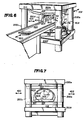
- FIGURES 8-9 Another exemplary embodiment is depicted in FIGURES 8-9. It is essentially similar to that of FIGURES 6-7 except that the structure is rotated by 90° so that the static magnetic field H o is oriented in a horizontal direction rather than vertically. And, as a further consequence of such rotation, the transverse open access port 400 is also now disposed vertically with respect to the patient transport axis-z. In some circumstances, this orientation of an open access port may be preferred since the patient will typically view an unobstructed area as he/she passes face up into the imaging volume along the patient transport axis-z.
- body coil structures 600 and 601 are depicted for illustration purposes in FIGURES 6-9, other types of RF coil structures (e.g., head coils, surface coils, etc.) may be used in addition or alternatively depending upon the MRI imaging procedure to be employed.
- RF coil structures may be constructed so as to have narrow z-axis dimensions and/or to be partially transparent and/or to have limited access ports therethrough if desired. Even if no such access ports are provided, a substantially more open presentation is made to the patient (thus minimizing possible claustrophobic reactions) and substantially greater access is provided (e.g., so as to adjust the RF coils if for no other purpose) to operating personnel.
Landscapes
- Physics & Mathematics (AREA)
- Condensed Matter Physics & Semiconductors (AREA)
- General Physics & Mathematics (AREA)
- Magnetic Resonance Imaging Apparatus (AREA)
- Measuring And Recording Apparatus For Diagnosis (AREA)
- Closed-Circuit Television Systems (AREA)
Abstract
Description
- This invention relates generally to magnetic resonance imaging (MRI) systems. In particular, it relates to the spatial arrangement of the (static and gradient) magnetic field generating components of an MRI system so as to maximize open and unobstructed patient access areas communicating directly with an MRI imaging volume along directions perpendicular to the patient transport axis.
- The art of magnetic resonance imaging (MRI) is now well developed and several different types of MRI systems are commercially available. In all of them, some means is provided to produce a very strong static magnetic field Ho and controlled spatial gradients therein (e.g., along three mutually orthogonal coordinate axes). The static magnetic field is typically of an approximately homogenous nature within a predefined imaging volume and the controlled gradients are typically approximately linear with respect to spatial displacements there-within.
- A programmed sequence of radio frequency pulses is transmitted into body portions located within the imaging volume at predetermined frequency distributions so as to selectively nutate the magnetic moment of certain atoms by predetermined amounts in accordance with well-known nuclear magnetic resonance (NMR) principles. After cessation of such transmitted RF pulses, the NMR nutated atoms tend to relax back toward alignment with the static magnetic field Ho and, in the process, produce characteristic NMR RF signals. Such RF signals are received, detected and processed to thereafter produce a desired MRI image of the body portion located within the imaging area in accordance with any one of many known MRI techniques as will be appreciated by those in the art. The transmitted RF pulses typically are synchronized with a special sequence of current pulses passed through various magnetic gradient coils during the imaging process so as to effect spatial information encoding processes and/or to provide known types of NMR phasing control.
- In some MRI apparatus, the static magnetic field Ho and/or the magnetic gradient coils are realized in the form of large solenoidal coils or, in the case of gradient coils, saddle-shaped coils conformed to a generally tubular configuration. In such cases, it is naturally necessary for patient access to the imaging volume to be provided only along a narrow tunnel through the tubular shaped apparatus. With some patients, this may give rise to claustrophobic reactions. It also makes it extremely cumbersome to access the image volume (e.g., so as to adjust the relative positioning of RF transmit and/or receive coils or to attend to patient needs).
- Other types of MRI systems utilize a pair of magnetic poles (e.g., permanent magnets or electromagnetic magnets with ferromagnetic or air cores) disposed on opposite sides of the image volume to create the requisite static magnetic field Ho. In the past, either necessary magnetic circuits for return flux (i.e., outside the image volume) between the magnetic poles and/or the magnetic gradient coils (e g., in a tubular form rather than flat) or decorative cover systems have been constructed so as to also limit access to the image volume except along a generally tunnel-shaped area through which the patient is transported into the image volume. Thus, as with the solenoidal field generating devices, access to the image volume has been essentially limited to only one or two open and unobstructed patient access ports or areas -- i.e., the ends of the patient transport tunnel aligned with the patient transport axis.
- Some typical examples of the latter type of prior art MRI system structures are depicted in Figures 1-3. In each case, access to the
image volume 10 is limited to either a single port (Figure 2) or a pair of aligned ports (Figures 1 and 3) along thepatient transport axis 12. In every case, there is no open and unobstructed patient access path communicating directly with theimage volume 10 in a direction perpendicular to thepatient transport axis 12. Instead, any such potential access is blocked either by return magnetic flux circuit structure 14 and/or by a gradient coil, (Figure 1) and/or by housing structure 16 (Figures 2 and 3). As those in the art will appreciate, behind thehousing structures 16 are typically further obstructions to access in directions perpendicular to the patient transport axis 12 (e g., magnetic flux return circuits and/or magnetic gradient coil structures or the like). - I have now discovered an improved magnetic resonance imaging apparatus wherein the static field magnet and gradient coil and decorative cover structures are configured so as to leave an open and obstructed patient access area communicating directly with the image volume along a direction perpendicular to the patient transport axis. In the preferred exemplary embodiment, such transverse access to the imaging volume may be had from two opposite sides of the patient transport mechanism while in yet another exemplary embodiment, such transverse access to the imaging volume passes virtually through the top of the MRI system. In such exemplary embodiments, magnetic flux return circuits are preferably in the form of cylindrical columns (e.g., four of them) disposed radially outwardly of the magnetic poles. In this manner, transverse unobstructed access to the imaging volume is provided not only along the patient transport axis but also through at least one additional transverse port provided between such columnar return flux circuit structures. Although the four column static magnet construction is a standard available vendor design, I have taken unique advantage of such an open static magnet structure by coordinating gradient coil and housing structures so as to maintain such "openness" in the final completed MRI structure. That is, no obstructing housings or other structures are used to obstruct such transverse access paths
- Accordingly, in the preferred exemplary embodiment of this invention, a magnetic resonance imaging apparatus includes a main static magnetic field structure for producing the requisite static magnetic field Ho within a predetermined patient imaging volume through which a patient transport is arranged along a predetermined Z axis. Magnetic gradient coils associated with the main static field structure are provided for effecting controlled gradients in the static magnetic field Ho along mutually orthogonal x,y,z axes within the patient imaging volume. However, the main static field structure and the gradient coils are configured so as to leave an open and unobstructed patient access area/path communicating directly with the imaging volume along a direction that is perpendicular to the patient transport z-axis
- Indeed, in the preferred exemplary embodiment, permanent magnet poles are disposed with horizontal pole planes below and above the imaging volume so as to produce a vertically oriented Ho field -- while magnetic flux return paths are provided through four vertical columns which also support the upper permanent magnet structure above the imaging volume. In this manner patient transport access is provided along the z-axis into and out of the imaging volume while a pair of opposing, open and unobstructed patient access areas/paths also communicate directly and transversely with the imaging volume along directions perpendicular to the patient transport z-axis.
- Stated somewhat differently, in the exemplary embodiment, there are at least three (and preferably at least four) open and unobstructed patient access areas communicating directly with the imaging volume along respective directions which are all perpendicular to the static Ho field -- and at least one (preferably two) of which is(are) also perpendicular to the patient transport axis z.
- These as well as other objects and advantages of this invention will be more completely understood and appreciated by carefully reading the following detailed description of the presently preferred exemplary embodiments taken in conjunction with the accompanying drawings, of which:
- FIGURES 1-3 are perspective views of typical prior art arrangements for MRI apparatus;
- FIGURE 4 is schematic drawing depicting the presently preferred exemplary embodiment of this invention wherein open access to the imaging volume is provided in four different directions, all perpendicular to the static magnetic field Ho and two of which are also perpendicular to the patient transport axis;
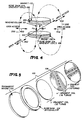
- FIGURE 5 is an exploded perspective view of a typical permanent magnet, shim and gradient coil structure disposed both above and below the imaging volume in the exemplary embodiment of FIGURE 4;
- FIGURES 6 and 7, respectively, provide a perspective and an end view of a preferred exemplary embodiment of the apparatus schematically depicted in FIGURE 4 and employing four vertical columns for return magnetic flux; and
- FIGURES 8 and 9 depict a further exemplary embodiment wherein the permanent magnets are rotated by 90° with respect to the embodiment of FIGURES 6-7 thus leaving open transverse access to the imaging volume from the top only (assuming that the bottom portion of the structure rests upon a floor support or the like).
- As will be appreciated throughout the following discussion, the denomination of specific axes as being x,y, or z axes is purely a matter of convention adopted to facilitate description of relative directions and dimensions in one exemplary embodiment. Other definitions may alternatively be used for descriptive purposes.
- As depicted in FIGURE 4, the
imaging volume 50 is sandwiched between upper and lower magneticfield producing assemblies 100. Within the imaging volume 50 (e.g., a 30 cm diameter spherical volume), cooperatingpermanent magnets 102 create a substantially homogenous static magnetic field Ho (e.g., 650 Gauss ± 100 ppm with a gap width between magnet poles of approximately 60 cm and a magnet pole diameter of approximately 1300 mm). Conventional "Rose"shims 104 may be used to help insure sufficient field uniformity within theimaging volume 50. - The
permanent magnets 102 and Roseshims 104 are of conventional design using conventional ferrite materials with iron or steel pole tips. For example, suitable such permanent magnets (with shims) are available from Sumitomo Special Metals Company Ltd., Osaka, Japan. - An exploded view of the
assembly 100 comprisingpermanent magnet 102,Rose shim 104 andgradient coils 106 is shown at FIGURE 5. The gradient coil structures may also be of conventional design. In general, the y-gradient coil comprises circular loops while the x and z-gradient coils comprise respectively orthogonal sets of back-to-back D-shaped coils arranged so that current in the parallel straight conductor segments within each set passes in the same direction. In the exemplary embodiment, the individual coil windings are formed from approximately .1 inch square copper wire with the active straight portion of the turns being spaced apart from one another by approximately one conductor width. - In the exemplary embodiment, the
gradient coils 106 are sandwiched together as closely as possible (with suitable allowances for insulating fiberglass/epoxy tape and potting materials) and fitted within theannular Rose shim 104. Thus, thegradient coils 106 are substantially parallel to the face ofpermanent magnet 102 and the composite magneticfield producing structure 100 is an essentially "flat" or "pancake" type of structure. - As those in the art will appreciate, the
gradient coils 106 as well as suitable RF coils are connected to suitable electrical driving, RF transmitting and RF receiving circuits (not shown) so as to complete an NMR imaging system. - As those in the art will also appreciate, suitable
magnetic circuits 200 must be provided for return flux between thepermanent magnets 102 located outside theimaging volume 50. In the preferred exemplary embodiment, such return paths are located so as to leave open access along opposingpatient transport ports patient access ports imaging volume 50 along directions perpendicular to the patient transport axis-z. - In the exemplary embodiment of FIGURES 6-7, the magnetic
flux return circuit 200 comprises flux conductive (e.g., iron or steel)members cylindrical columns 200a-200d suffice to concentrate most of the return flux between upper andlower members field producing structures 100 near the center of the apparatus). A suitablepatient transport structure 500 may be utilized for transporting a patient into and out of the imaging volume throughopen access ports open access ports - Accordingly, as a patient passes into the imaging volume, an essentially open and substantially unobstructed feeling is encountered so as to suppress or minimize possible claustrophobic reactions. Furthermore, doctors, technicians, nurses and/or MRI system operating personnel have ready access to the imaging volume for the purpose of attending to patient needs and/or adjusting
RF coils - Although some sort of
RF coil structures suitable access ports 602, 604 (or maybe made so as to be at least partially transparent in selected areas) or may be of very narrow dimensions in the z axis direction. - Although the basic structure of the
magnets 102 andreturn flux structures 200a-200f may be conventional in and of themselves (e.g., as available from Sumitomo Special Metals Company, Ltd.), use heretofore with MRI systems has failed to utilize the potential for transverse open access areas as in the embodiment of FIGURES 6-7. Instead, prior approaches have used additional magnetic flux return circuit components and/or other types of magnetic gradient coil structures and/or other types of external housings so as to effectively obstruct access to theimaging volume 50 except along a narrow patient transport tunnel. - Another exemplary embodiment is depicted in FIGURES 8-9. It is essentially similar to that of FIGURES 6-7 except that the structure is rotated by 90° so that the static magnetic field Ho is oriented in a horizontal direction rather than vertically. And, as a further consequence of such rotation, the transverse
open access port 400 is also now disposed vertically with respect to the patient transport axis-z. In some circumstances, this orientation of an open access port may be preferred since the patient will typically view an unobstructed area as he/she passes face up into the imaging volume along the patient transport axis-z. - Although
body coil structures - Although only a few exemplary embodiments of this invention have been described in detail, those skilled in the art will recognize that many variations and modifications may be made in these exemplary embodiments while yet maintaining many of the novel features and advantages of this invention. Accordingly, all such variations and modifications are intended to be included within the scope of the appended claims.
Claims (16)
main static magnetic field means for producing a static magnetic field Ho within a predetermined patient imaging volume;
patient transport means for transporting a patient into said imaging volume along a predetermined z-axis; and
magnetic gradient coil means associated with said main static magnetic field means for effecting controlled gradients in said Ho field along mutually orthogonal axes within said patient imaging volume;
said main static magnetic field means and said gradient coil means being configured to leave an open and unobstructed patient access area communicating directly with said imaging volume along a direction perpendicular to said z-axis.
main static magnetic field means for producing a static magnetic field Ho within a predetermined patient imaging volume; and
magnetic gradient coil means associated with said main static magnetic field means for effecting controlled gradients in said Ho field along mutually orthogonal axes within said patient imaging volume;
said main field producing means and said gradient coil means being configured to leave at least three separated, open and unobstructed patient access areas communicating directly with said imaging volume along respective directions perpendicular to said Ho field.
a pair of magnetic pole pieces opposingly disposed about a patient imaging volume located therebetween so as to produce a predetermined approximately homogeneous static magnetic field directed between said pole pieces parallel to a predetermined y-axis;
patient transport means for transporting at least a portion of a patient along a predetermined z-axis into said imaging volume, said z-axis being substantially perpendicular to said y-axis;
magnetic return circuit means for conducting return magnetic flux from one said pole piece to the other and located outside said imaging volume; and
a plurality of magnetic gradient coils disposed substantially parallel to said pole pieces for producing controlled gradients in said static magnetic field in directions parallel to said y and z axes and to a predetermined x-axis, which x-axis is mutually orthogonal to said y and z axes;
said magnetic return circuit means and said gradient coils being configured to leave open and unobstructed at least three patient access areas:
said third patient access area is directed vertically and parallel to said x-axis.
said third patient access area is directed horizontally and parallel to said x-axis.
said magnetic return circuit means and said gradient coils are configured to leave open and unobstructed a fourth patient access area opposite said third patient access area and also communicating directly with said imaging volume along a horizontal direction parallel to said x-axis.
said magnetic return circuit means includes four cylindrical vertically disposed columns which support a first one of pole pieces in a horizontal plane above the other pole piece while also conducting said return magnetic flux and providing four open and unobstructed patient access areas therebetween directed horizontally and perpendicular to said y-axis.
a first magnetic pole piece disposed on a first side of a patient image area;
a second magnetic pole piece disposed on a second side of the patient image area opposite said first side;
at least three magnetic circuit members interconnecting corresponding peripheral portions of said pole pieces and defining at least three open access ports therebetween into said patient image area;
magnetic gradient coil means disposed adjacent said pole pieces on either side of said patient image area while leaving said open access ports substantially unobstructed; and
patient support means for transporting a patient through one of said open access ports into said patient image area while leaving the remaining ports with open access whereby patient claustrophobic reactions are reduced while also facilitating ready access to the patient image area.
each said pole piece has a circular end face disposed in a generally horizontal plane and directed toward said patient image area; and
said magnetic circuit members include four cylindrical support members disposed vertically so as to support said first pole piece above said second pole piece while also providing a return magnetic circuit therebetween.
each pole piece has a circular end face disposed in a generally vertical plane and directed toward said patient image area; and
said magnetic circuit members include four cylindrical members disposed horizontally so as to provide a return magnetic circuit therebetween while leaving an open access port at each end and at the top of said patient image area.
Applications Claiming Priority (2)
| Application Number | Priority Date | Filing Date | Title |
|---|---|---|---|
| US07/113,443 US4829252A (en) | 1987-10-28 | 1987-10-28 | MRI system with open access to patient image volume |
| US113443 | 1987-10-28 |
Publications (3)
| Publication Number | Publication Date |
|---|---|
| EP0314262A2 true EP0314262A2 (en) | 1989-05-03 |
| EP0314262A3 EP0314262A3 (en) | 1990-09-05 |
| EP0314262B1 EP0314262B1 (en) | 1994-06-01 |
Family
ID=22349444
Family Applications (1)
| Application Number | Title | Priority Date | Filing Date |
|---|---|---|---|
| EP88303465A Expired - Lifetime EP0314262B1 (en) | 1987-10-28 | 1988-04-18 | MRI system with open access to patient image volume |
Country Status (5)
| Country | Link |
|---|---|
| US (1) | US4829252A (en) |
| EP (1) | EP0314262B1 (en) |
| JP (1) | JPH01146530A (en) |
| AT (1) | ATE106560T1 (en) |
| DE (1) | DE3889847T2 (en) |
Cited By (16)
| Publication number | Priority date | Publication date | Assignee | Title |
|---|---|---|---|---|
| EP0373000A2 (en) * | 1988-12-09 | 1990-06-13 | Picker International Limited | Magnetic resonance apparatus |
| WO1990010877A1 (en) * | 1989-03-11 | 1990-09-20 | Bruker Analytische Messtechnik Gmbh | Magnet system |
| EP0424808A1 (en) * | 1989-10-21 | 1991-05-02 | Kabushiki Kaisha Toshiba | Magnetic resonance imaging apparatus |
| WO1991017454A1 (en) * | 1990-04-27 | 1991-11-14 | Oxford Medical Limited | Magnetic field generating assembly |
| EP0498528A2 (en) * | 1991-02-04 | 1992-08-12 | The Regents Of The University Of California | Real-time mr imaging inside gantry room |
| EP0517452A1 (en) * | 1991-06-03 | 1992-12-09 | General Electric Company | Open MRI magnet |
| EP0618457A1 (en) * | 1993-04-01 | 1994-10-05 | Shin-Etsu Chemical Co., Ltd. | Magnet apparatus for magnetic resonance imaging |
| WO1995010786A2 (en) * | 1993-10-11 | 1995-04-20 | Innervision Mri Limited | Apparatus for magnetic resonance measurement |
| EP0654675A1 (en) * | 1993-11-22 | 1995-05-24 | Picker International, Inc. | Magnetic resonance apparatus and methods |
| US5436607A (en) * | 1992-08-05 | 1995-07-25 | General Electric Company | Open (non-enclosed) magnets for magnetic resonance imaging |
| US5666056A (en) * | 1993-08-02 | 1997-09-09 | U.S. Philips Corporation | Magnetic resonance imaging apparatus |
| EP0830847A3 (en) * | 1996-09-18 | 1999-10-20 | Hitachi, Ltd. | Surgical operating apparatus |
| EP0965852A2 (en) * | 1998-06-19 | 1999-12-22 | Sumitomo Special Metals Company Limited | Packing member for an MRI magnet and method for packing the same |
| EP1039308A2 (en) * | 1994-11-25 | 2000-09-27 | Hitachi Medical Corporation | Magnetic resonance imaging system |
| EP1148341A2 (en) * | 2000-04-19 | 2001-10-24 | GE Medical Systems Global Technology Company LLC | Method of manufacturing gradient coil, gradient coil and magnetic resonance imaging system |
| DE10116802C1 (en) * | 2001-04-04 | 2002-10-02 | Siemens Ag | RF antenna for an open MR system |
Families Citing this family (115)
| Publication number | Priority date | Publication date | Assignee | Title |
|---|---|---|---|---|
| US5207224A (en) * | 1988-12-09 | 1993-05-04 | Picker International, Ltd. | Magnetic resonance apparatus |
| US4943774A (en) * | 1989-06-01 | 1990-07-24 | General Atomics | Magnetic field control apparatus |
| US5036282A (en) * | 1989-06-16 | 1991-07-30 | Picker International, Inc. | Biplanar gradient coil for magnetic resonance imaging systems |
| US4980641A (en) * | 1989-08-11 | 1990-12-25 | General Atomics | Method and apparatus of reducing magnetic hysteresis in MRI systems |
| US5304932A (en) * | 1990-11-05 | 1994-04-19 | The Regents Of The University Of California | Apparatus and method for shielding MRI RF antennae from the effect of surrounding objects |
| CA2097430C (en) * | 1990-12-04 | 2003-06-24 | Melvin Miller | System for logging a well during the drilling thereof |
| US5227728A (en) * | 1991-11-01 | 1993-07-13 | The Regents Of The University Of California | Gradient driver control in magnetic resonance imaging |
| US5250901A (en) * | 1991-11-07 | 1993-10-05 | The Regents Of The University Of California | Open architecture iron core electromagnet for MRI using superconductive winding |
| US5412363A (en) * | 1991-12-20 | 1995-05-02 | Applied Superconetics, Inc. | Open access superconducting MRI magnet |
| US5365173A (en) * | 1992-07-24 | 1994-11-15 | Picker International, Inc. | Technique for driving quadrature dual frequency RF resonators for magnetic resonance spectroscopy/imaging by four-inductive loop over coupling |
| EP0581666B1 (en) * | 1992-07-30 | 1997-10-01 | Schlumberger Limited | Pulsed nuclear magnetism tool for formation evaluation while drilling |
| US5923167A (en) * | 1992-07-30 | 1999-07-13 | Schlumberger Technology Corporation | Pulsed nuclear magnetism tool for formation evaluation while drilling |
| US5442290A (en) * | 1992-08-04 | 1995-08-15 | The Regents Of The University Of California | MRI gradient drive current control using all digital controller |
| US5305749B1 (en) * | 1992-09-24 | 2000-05-02 | Univ California | Side-loading of patient into mri c-magnet while maintaining adjacent open accessibility to patient |
| US6023165A (en) | 1992-09-28 | 2000-02-08 | Fonar Corporation | Nuclear magnetic resonance apparatus and methods of use and facilities for incorporating the same |
| US5754085A (en) * | 1992-09-28 | 1998-05-19 | Fonar Corporation | Ferromagnetic yoke magnets for medical magnetic resonance studies |
| US5606970A (en) * | 1992-09-28 | 1997-03-04 | Fonar Corporation | Multiple patient scanning on a magnetic resonance imaging apparatus |
| US6456075B1 (en) | 1992-12-18 | 2002-09-24 | Fornar Corporation | MRI magnet with enhanced patient entry and positioning |
| US6201394B1 (en) | 1992-12-18 | 2001-03-13 | Fonar Corporation | MRI apparatus |
| US6414490B1 (en) | 1992-12-18 | 2002-07-02 | Fonar Corporation | MRI magnet with enhanced patient entry and positioning |
| US6335623B1 (en) | 1992-12-18 | 2002-01-01 | Fonar Corporation | MRI apparatus |
| US5386191A (en) * | 1993-03-01 | 1995-01-31 | The Regents Of The University Of California | RF coil providing reduced obstruction access to image volume in transverse magnet MRI system |
| US5357958A (en) * | 1993-03-18 | 1994-10-25 | The Regents Of The University Of California | Interventional MRI system and RF coils therefore |
| US5490509A (en) * | 1993-03-18 | 1996-02-13 | The Regents Of The University Of California | Method and apparatus for MRI using selectively shaped image volume of homogeneous NMR polarizing field |
| GB2278685B (en) * | 1993-05-27 | 1997-07-30 | Elscint Ltd | Superconducting magnet |
| DE4324021C2 (en) * | 1993-07-17 | 1996-05-30 | Bruker Analytische Messtechnik | Therapy tomograph |
| US5381122A (en) * | 1994-01-14 | 1995-01-10 | General Electric Company | Open MRI magnet having a support structure |
| US5517121A (en) * | 1995-01-13 | 1996-05-14 | Toshiba America Mri, Inc. | MRI system with side-access to an image volume located within a two-column main magnet |
| US5799653A (en) * | 1995-10-03 | 1998-09-01 | Toshiba America Mri, Inc. | Magnetic resonance imaging apparatus with decreased patient claustrophobia and increased access to patient |
| US6512371B2 (en) | 1995-10-12 | 2003-01-28 | Halliburton Energy Services, Inc. | System and method for determining oil, water and gas saturations for low-field gradient NMR logging tools |
| US6956371B2 (en) * | 1995-10-12 | 2005-10-18 | Halliburton Energy Services, Inc. | Method and apparatus for detecting diffusion sensitive phases with estimation of residual error in NMR logs |
| JP3731231B2 (en) * | 1995-11-30 | 2006-01-05 | 株式会社日立メディコ | Superconducting magnet device |
| US6028429A (en) * | 1996-07-17 | 2000-02-22 | Fonar Corporation | Composite MRI antenna with reduced stray capacitance |
| US5939883A (en) * | 1996-07-17 | 1999-08-17 | Fonar Corporation | Magnetic resonance imaging excitation and reception methods and apparatus |
| US5900793A (en) * | 1997-07-23 | 1999-05-04 | Odin Technologies Ltd | Permanent magnet assemblies for use in medical applications |
| US6150911A (en) * | 1996-07-24 | 2000-11-21 | Odin Technologies Ltd. | Yoked permanent magnet assemblies for use in medical applications |
| US5939962A (en) * | 1996-08-07 | 1999-08-17 | Mitsubishi Denki Kabushiki Kaisha | Split type magnetic field generating apparatus for MRI |
| USD386261S (en) * | 1996-10-01 | 1997-11-11 | Toshiba America Mri, Inc. | Magnetic resonance imaging system |
| IL119558A (en) | 1996-11-04 | 2005-11-20 | Odin Technologies Ltd | Multi-probe mri/mrt system |
| US6531868B2 (en) | 1996-12-30 | 2003-03-11 | Halliburton Energy Services, Inc. | System and methods for formation evaluation while drilling |
| US6011393A (en) * | 1997-06-26 | 2000-01-04 | Toshiba America Mri, Inc. | Self-supporting RF coil for MRI |
| JP3104863B2 (en) * | 1997-07-11 | 2000-10-30 | 株式会社日立メディコ | Magnetic resonance imaging equipment |
| US6411187B1 (en) | 1997-07-23 | 2002-06-25 | Odin Medical Technologies, Ltd. | Adjustable hybrid magnetic apparatus |
| US6157278A (en) * | 1997-07-23 | 2000-12-05 | Odin Technologies Ltd. | Hybrid magnetic apparatus for use in medical applications |
| US6081117A (en) * | 1997-08-11 | 2000-06-27 | Panacea Medical Laboratories | Noise modulation for open access and remotely positioned MRI |
| AU9364698A (en) * | 1997-09-25 | 1999-04-12 | Odin Technologies Ltd. | Magnetic apparatus for mri |
| US6437571B1 (en) | 1997-11-21 | 2002-08-20 | Fonar Corporation | MRI apparatus |
| WO1999040593A1 (en) * | 1998-02-09 | 1999-08-12 | Odin Medical Technologies Ltd | A method for designing open magnets and open magnetic apparatus for use in mri/mrt probes |
| US6208143B1 (en) | 1998-04-10 | 2001-03-27 | The Board Of Trustee Of The Leland Stanford Junior University | Biplanar homogeneous field electromagnets and method for making same |
| US6593742B1 (en) | 1998-04-10 | 2003-07-15 | The Board Of Trustees Of The Leland Stanford Junior University | Biplanar homogeneous field electromagnets and method for making same |
| US6377042B1 (en) | 1998-08-31 | 2002-04-23 | Numar Corporation | Method and apparatus for merging of NMR echo trains in the time domain |
| JP2000107151A (en) | 1998-09-30 | 2000-04-18 | Toshiba Corp | Magnetic resonance imaging apparatus |
| US6366087B1 (en) | 1998-10-30 | 2002-04-02 | George Richard Coates | NMR logging apparatus and methods for fluid typing |
| US6249121B1 (en) | 1999-05-17 | 2001-06-19 | General Electric Company | RF body coil |
| JP3283242B2 (en) * | 1999-06-21 | 2002-05-20 | ジーイー横河メディカルシステム株式会社 | Gradient coil manufacturing method, gradient coil and MRI apparatus |
| US6661226B1 (en) | 1999-08-13 | 2003-12-09 | Halliburton Energy Services, Inc. | NMR apparatus and methods for measuring volumes of hydrocarbon gas and oil |
| US6255819B1 (en) | 1999-10-25 | 2001-07-03 | Halliburton Energy Services, Inc. | System and method for geologically-enhanced magnetic resonance imaging logs |
| US6677753B1 (en) | 1999-11-24 | 2004-01-13 | Fonar Corporation | Stand-up MRI apparatus |
| US6828792B1 (en) | 1999-11-24 | 2004-12-07 | Fonar Corporation | MRI apparatus and method for imaging |
| JP3705996B2 (en) * | 2000-04-26 | 2005-10-12 | ジーイー・メディカル・システムズ・グローバル・テクノロジー・カンパニー・エルエルシー | Magnetic resonance imaging device |
| US7196519B2 (en) * | 2000-07-28 | 2007-03-27 | Fonar Corporation | Stand-up vertical field MRI apparatus |
| US8190234B2 (en) | 2000-07-28 | 2012-05-29 | Fonar Corporation | Movable patient support with spatial locating feature |
| US7697971B1 (en) | 2000-07-28 | 2010-04-13 | Fonar Corporation | Positioning system for an MRI |
| US6822449B1 (en) | 2000-11-22 | 2004-11-23 | Fonar Corporation | Ferromagnetic frame with laminated carbon steel |
| US6521210B2 (en) | 2000-12-13 | 2003-02-18 | Archimedes Technology Group, Inc. | Method for imaging malignant tumors using carbon 13 with MRI |
| US6577125B2 (en) | 2000-12-18 | 2003-06-10 | Halliburton Energy Services, Inc. | Temperature compensated magnetic field apparatus for NMR measurements |
| US6940378B2 (en) | 2001-01-19 | 2005-09-06 | Halliburton Energy Services | Apparatus and method for magnetic resonance measurements in an interior volume |
| US6650730B2 (en) | 2001-01-23 | 2003-11-18 | Fartech, Inc. | Filter assembly for X-ray filter system for medical imaging contrast enhancement |
| US6614878B2 (en) | 2001-01-23 | 2003-09-02 | Fartech, Inc. | X-ray filter system for medical imaging contrast enhancement |
| US6717408B2 (en) | 2001-04-05 | 2004-04-06 | Intermagnetics General Corporation | Support structure for open MRI apparatus |
| US6934574B1 (en) | 2001-06-21 | 2005-08-23 | Fonar Corporation | MRI scanner and method for modular patient handling |
| DE10147742B4 (en) * | 2001-09-27 | 2005-05-19 | Siemens Ag | Magnetic resonance apparatus with a horizontal basic magnetic field |
| US6944492B1 (en) | 2001-10-01 | 2005-09-13 | Fonar Corporation | Patient bed support for an open MRI system |
| US7701209B1 (en) | 2001-10-05 | 2010-04-20 | Fonar Corporation | Coils for horizontal field magnetic resonance imaging |
| US7906966B1 (en) | 2001-10-05 | 2011-03-15 | Fonar Corporation | Quadrature foot coil antenna for magnetic resonance imaging |
| JP4045769B2 (en) * | 2001-10-10 | 2008-02-13 | 株式会社日立製作所 | Magnetic field generator and MRI apparatus using the same |
| JP4746270B2 (en) * | 2002-02-15 | 2011-08-10 | メドトロニック・ナビゲーション・インコーポレーテッド | Gantry ring for multidimensional X-ray imaging equipment with removable part |
| EP1482837B1 (en) * | 2002-03-13 | 2005-09-14 | Breakaway Imaging, Llc | Systems and methods for quasi-simultaneous multi-planar x-ray imaging |
| EP2915488B1 (en) * | 2002-03-19 | 2019-06-05 | Medtronic Navigation, Inc. | Computer tomography with a detector following the movement of a pivotable x-ray source |
| US8036730B1 (en) | 2002-04-19 | 2011-10-11 | Fonar Corporation | Temporal magnetic resonance imaging |
| US7123008B1 (en) | 2002-04-19 | 2006-10-17 | Fonar Corporation | Positional magnetic resonance imaging |
| AU2003245439A1 (en) * | 2002-06-11 | 2003-12-22 | Breakaway Imaging, Llc | Cantilevered gantry apparatus for x-ray imaging |
| JP4143812B2 (en) * | 2002-07-01 | 2008-09-03 | 株式会社日立メディコ | Magnetic resonance imaging system |
| WO2004019279A2 (en) * | 2002-08-21 | 2004-03-04 | Breakaway Imaging, Llc | Apparatus and method for reconstruction of volumetric images in a divergent scanning computed tomography system |
| EP1531727B8 (en) * | 2002-08-21 | 2010-08-11 | Medtronic Navigation, Inc. | Gantry positioning apparatus for x-ray imaging |
| JP3594948B2 (en) * | 2002-08-26 | 2004-12-02 | ジーイー横河メディカルシステム株式会社 | MRI system |
| US6956372B2 (en) * | 2002-09-11 | 2005-10-18 | Halliburton Energy Services, Inc. | System and method for NMR logging with helical polarization |
| WO2004047640A1 (en) * | 2002-11-25 | 2004-06-10 | Fonar Corporation | Method, apparatus, and facility for mri dual scanning |
| US8064984B2 (en) * | 2003-03-18 | 2011-11-22 | Esaote S.P.A. | Magnetic resonance imaging apparatus |
| US7463027B2 (en) * | 2003-05-02 | 2008-12-09 | Halliburton Energy Services, Inc. | Systems and methods for deep-looking NMR logging |
| MXPA06003671A (en) * | 2003-10-03 | 2006-06-20 | Halliburton Energy Serv Inc | System and methods for t1-based logging. |
| DE10346275B4 (en) * | 2003-10-06 | 2005-08-18 | Siemens Ag | Producer of time-variable magnetic fields of a magnetic resonance apparatus and magnetic resonance apparatus with the producer |
| EP1794609A2 (en) * | 2004-09-27 | 2007-06-13 | Fonar Corporation | Magnetic resonance imaging system, apparatus and associated methods |
| US8401615B1 (en) | 2004-11-12 | 2013-03-19 | Fonar Corporation | Planar coil flexion fixture for magnetic resonance imaging and use thereof |
| DE102005007851A1 (en) * | 2005-02-21 | 2006-08-24 | Siemens Ag | Irradiation apparatus for irradiating a living organism with electromagnetic radiation to affect the biologic structure of the organism |
| US8401612B1 (en) | 2006-09-11 | 2013-03-19 | Fonar Corporation | Magnetic resonance imaging system and method for detecting chiari malformations |
| JP4237786B2 (en) * | 2006-09-27 | 2009-03-11 | 株式会社日立製作所 | Nuclear magnetic resonance signal solenoid coil and nuclear magnetic resonance probe |
| EP1944617A1 (en) * | 2007-01-11 | 2008-07-16 | RWTH Aachen | Method and apparatus for providing a sensitive volume for single-sided NMR |
| US8219176B2 (en) * | 2007-03-08 | 2012-07-10 | Allegheny-Singer Research Institute | Single coil parallel imaging |
| US7541808B2 (en) * | 2007-04-11 | 2009-06-02 | Allegheny-Singer Research Institute | Rapid MRI dynamic imaging using MACH |
| US20110179681A1 (en) * | 2007-04-25 | 2011-07-28 | Jennifer Beth Lamers | Method and device for marking, identifying and organizing personal clothing |
| US9386939B1 (en) | 2007-05-10 | 2016-07-12 | Fonar Corporation | Magnetic resonance imaging of the spine to detect scoliosis |
| US8599215B1 (en) | 2008-05-07 | 2013-12-03 | Fonar Corporation | Method, apparatus and system for joining image volume data |
| US8688193B2 (en) * | 2008-06-26 | 2014-04-01 | Allegheny-Singer Research Institute | Magnetic resonance imager, method and program which continuously applies steady-state free precession to k-space |
| US7834629B2 (en) * | 2008-09-11 | 2010-11-16 | Allegheny-Singer Research Institute | Hybrid MRI and method |
| US8131046B2 (en) * | 2008-10-29 | 2012-03-06 | Allegheny-Singer Research Institute | Magnetic resonance imager using cylindrical offset region of excitation, and method |
| US8198892B2 (en) * | 2009-04-22 | 2012-06-12 | Allegheny-Singer Research Institute | Steady-state-free-precession (SSFP) magnetic resonance imaging (MRI) and method |
| US8405394B2 (en) * | 2009-10-20 | 2013-03-26 | Allegheny-Singer Research Institute | Targeted acquisition using holistic ordering (TACHO) approach for high signal to noise imaging |
| US20110215805A1 (en) * | 2010-03-03 | 2011-09-08 | Allegheny-Singer Research Institute | MRI and method using multi-slice imaging |
| EP2400314A1 (en) * | 2010-06-14 | 2011-12-28 | Agilent Technologies U.K. Limited | Superconducting magnet arrangement and method of mounting thereof |
| CN103732137B (en) * | 2011-08-09 | 2016-08-31 | 日立金属株式会社 | Coil device and MR imaging apparatus |
| GB201217782D0 (en) * | 2012-10-04 | 2012-11-14 | Tesla Engineering Ltd | Magnet apparatus |
| US11141080B1 (en) | 2013-03-13 | 2021-10-12 | Fonar Corporation | Cervical vertebra angle measurement |
| US10478087B2 (en) * | 2017-02-16 | 2019-11-19 | Aselsan Elektronik Sanayi Ve Ticaret A.S. | Open bore field free line magnetic particle imaging system |
| CN110169771B (en) * | 2019-04-02 | 2023-06-23 | 佛山瑞加图医疗科技有限公司 | Tiltable magnetic resonance apparatus |
Citations (7)
| Publication number | Priority date | Publication date | Assignee | Title |
|---|---|---|---|---|
| GB884129A (en) * | 1957-11-04 | 1961-12-06 | Perkin Elmer Corp | Device for the creation of a magnetic field |
| GB1201307A (en) * | 1966-09-08 | 1970-08-05 | Perkin Elmer Ltd | Magnet systems |
| EP0121367A2 (en) * | 1983-03-30 | 1984-10-10 | Picker International Limited | Nuclear magnetic resonance imaging apparatus |
| EP0161782A1 (en) * | 1984-04-11 | 1985-11-21 | Sumitomo Special Metal Co., Ltd. | Magnetic field generating device for NMR-CT |
| EP0217520A2 (en) * | 1985-08-23 | 1987-04-08 | Resonex, Inc. | Gradient field structure and method for use with magnetic resonance imaging apparatus |
| DE3639140A1 (en) * | 1985-11-18 | 1987-05-21 | Toshiba Kawasaki Kk | MAGNETIC RESONANCE SYSTEM |
| EP0262880A2 (en) * | 1986-09-27 | 1988-04-06 | Sumitomo Special Metals Co. Ltd. | Magnetic field generating device for NMR-CT |
Family Cites Families (7)
| Publication number | Priority date | Publication date | Assignee | Title |
|---|---|---|---|---|
| FI64282C (en) * | 1981-06-04 | 1983-11-10 | Instrumentarium Oy | DIAGNOSISPARATUR FOER BESTAEMMANDE AV VAEVNADERNAS STRUKTUR OC SAMMANSAETTNING |
| FR2541551A1 (en) * | 1983-02-21 | 1984-08-24 | Drusch & Cie | DEVICE FOR HOLDING AND FIXING COILS FOR REALIZING A CONSTANT AND HOMOGENEOUS MAGNETIC FIELD |
| US4629989A (en) * | 1983-11-10 | 1986-12-16 | General Electric Company | Patient alignment system for NMR studies |
| JPS60257109A (en) * | 1984-06-01 | 1985-12-18 | Sumitomo Special Metals Co Ltd | Magnetic field generating device |
| US4721914A (en) * | 1984-05-01 | 1988-01-26 | The United States Of America As Represented By The United States Department Of Energy | Apparatus for unilateral generation of a homogeneous magnetic field |
| US4634980A (en) * | 1984-08-16 | 1987-01-06 | Picker International, Inc. | Nuclear magnetic resonance radio frequency antenna |
| US4714886A (en) * | 1985-07-16 | 1987-12-22 | President And Fellows Of Harvard College | Magnetic resonance analysis of substances in samples that include dissipative material |
-
1987
- 1987-10-28 US US07/113,443 patent/US4829252A/en not_active Expired - Lifetime
-
1988
- 1988-04-18 EP EP88303465A patent/EP0314262B1/en not_active Expired - Lifetime
- 1988-04-18 AT AT88303465T patent/ATE106560T1/en not_active IP Right Cessation
- 1988-04-18 DE DE3889847T patent/DE3889847T2/en not_active Expired - Fee Related
- 1988-10-28 JP JP63271058A patent/JPH01146530A/en active Pending
Patent Citations (7)
| Publication number | Priority date | Publication date | Assignee | Title |
|---|---|---|---|---|
| GB884129A (en) * | 1957-11-04 | 1961-12-06 | Perkin Elmer Corp | Device for the creation of a magnetic field |
| GB1201307A (en) * | 1966-09-08 | 1970-08-05 | Perkin Elmer Ltd | Magnet systems |
| EP0121367A2 (en) * | 1983-03-30 | 1984-10-10 | Picker International Limited | Nuclear magnetic resonance imaging apparatus |
| EP0161782A1 (en) * | 1984-04-11 | 1985-11-21 | Sumitomo Special Metal Co., Ltd. | Magnetic field generating device for NMR-CT |
| EP0217520A2 (en) * | 1985-08-23 | 1987-04-08 | Resonex, Inc. | Gradient field structure and method for use with magnetic resonance imaging apparatus |
| DE3639140A1 (en) * | 1985-11-18 | 1987-05-21 | Toshiba Kawasaki Kk | MAGNETIC RESONANCE SYSTEM |
| EP0262880A2 (en) * | 1986-09-27 | 1988-04-06 | Sumitomo Special Metals Co. Ltd. | Magnetic field generating device for NMR-CT |
Cited By (29)
| Publication number | Priority date | Publication date | Assignee | Title |
|---|---|---|---|---|
| EP0373000A3 (en) * | 1988-12-09 | 1991-05-08 | Picker International Limited | Magnetic resonance apparatus |
| EP0373000A2 (en) * | 1988-12-09 | 1990-06-13 | Picker International Limited | Magnetic resonance apparatus |
| US5168211A (en) * | 1989-03-11 | 1992-12-01 | Bruker Analytische Messtechnik Gmbh | Magnet system |
| WO1990010877A1 (en) * | 1989-03-11 | 1990-09-20 | Bruker Analytische Messtechnik Gmbh | Magnet system |
| EP0424808A1 (en) * | 1989-10-21 | 1991-05-02 | Kabushiki Kaisha Toshiba | Magnetic resonance imaging apparatus |
| WO1991017454A1 (en) * | 1990-04-27 | 1991-11-14 | Oxford Medical Limited | Magnetic field generating assembly |
| US5337001A (en) * | 1990-04-27 | 1994-08-09 | Oxford Medical Limited | Magnetic field generating assembly |
| EP0498528A2 (en) * | 1991-02-04 | 1992-08-12 | The Regents Of The University Of California | Real-time mr imaging inside gantry room |
| EP0498528A3 (en) * | 1991-02-04 | 1992-12-02 | The Regents Of The University Of California | Real-time mr imaging inside gantry room |
| EP0517452A1 (en) * | 1991-06-03 | 1992-12-09 | General Electric Company | Open MRI magnet |
| US5436607A (en) * | 1992-08-05 | 1995-07-25 | General Electric Company | Open (non-enclosed) magnets for magnetic resonance imaging |
| EP0618457A1 (en) * | 1993-04-01 | 1994-10-05 | Shin-Etsu Chemical Co., Ltd. | Magnet apparatus for magnetic resonance imaging |
| US5382905A (en) * | 1993-04-01 | 1995-01-17 | Shin-Etsu Chemical Co., Ltd. | Magnet apparatus for magnetic resonance imaging |
| US5666056A (en) * | 1993-08-02 | 1997-09-09 | U.S. Philips Corporation | Magnetic resonance imaging apparatus |
| WO1995010786A3 (en) * | 1993-10-11 | 1995-06-01 | Innervision Mri Limited | Apparatus for magnetic resonance measurement |
| WO1995010786A2 (en) * | 1993-10-11 | 1995-04-20 | Innervision Mri Limited | Apparatus for magnetic resonance measurement |
| EP0654675A1 (en) * | 1993-11-22 | 1995-05-24 | Picker International, Inc. | Magnetic resonance apparatus and methods |
| US6218837B1 (en) | 1994-11-25 | 2001-04-17 | Hitachi Medical Corporation | Magnetic resonance imaging system |
| EP1039308A2 (en) * | 1994-11-25 | 2000-09-27 | Hitachi Medical Corporation | Magnetic resonance imaging system |
| EP1039308A3 (en) * | 1994-11-25 | 2000-12-06 | Hitachi Medical Corporation | Magnetic resonance imaging system |
| EP0830847A3 (en) * | 1996-09-18 | 1999-10-20 | Hitachi, Ltd. | Surgical operating apparatus |
| US6094590A (en) * | 1996-09-18 | 2000-07-25 | Hitachi, Ltd. | Surgical operating apparatus |
| EP0965852A2 (en) * | 1998-06-19 | 1999-12-22 | Sumitomo Special Metals Company Limited | Packing member for an MRI magnet and method for packing the same |
| EP0965852A3 (en) * | 1998-06-19 | 2000-12-13 | Sumitomo Special Metals Company Limited | Packing member for an MRI magnet and method for packing the same |
| US6313632B1 (en) | 1998-06-19 | 2001-11-06 | Sumitomo Special Metals Co., Ltd. | Magnetic field generator for MRI, packing member for the same, and method for packing the same |
| EP1148341A2 (en) * | 2000-04-19 | 2001-10-24 | GE Medical Systems Global Technology Company LLC | Method of manufacturing gradient coil, gradient coil and magnetic resonance imaging system |
| EP1148341A3 (en) * | 2000-04-19 | 2004-01-02 | GE Medical Systems Global Technology Company LLC | Method of manufacturing gradient coil, gradient coil and magnetic resonance imaging system |
| DE10116802C1 (en) * | 2001-04-04 | 2002-10-02 | Siemens Ag | RF antenna for an open MR system |
| US6798203B2 (en) | 2001-04-04 | 2004-09-28 | Siemens Aktiengesellschaft | RF antenna for an open MR system |
Also Published As
| Publication number | Publication date |
|---|---|
| JPH01146530A (en) | 1989-06-08 |
| US4829252A (en) | 1989-05-09 |
| DE3889847D1 (en) | 1994-07-07 |
| EP0314262B1 (en) | 1994-06-01 |
| EP0314262A3 (en) | 1990-09-05 |
| DE3889847T2 (en) | 1994-12-15 |
| ATE106560T1 (en) | 1994-06-15 |
Similar Documents
| Publication | Publication Date | Title |
|---|---|---|
| US4829252A (en) | MRI system with open access to patient image volume | |
| US5061897A (en) | Eddy current control in magnetic resonance imaging | |
| EP0760484B1 (en) | Opposed magnet-type magnetic circuit assembly with permanent magnets | |
| EP0084946B1 (en) | Apparatus for generating or detecting field components in a magnetic resonance system | |
| US5696449A (en) | RF coil for open MR magnet | |
| JP2584005B2 (en) | Magnetic field gradient coil device and magnetic resonance imaging system using the same | |
| US4794338A (en) | Balanced self-shielded gradient coils | |
| US5166619A (en) | Gradient coil assembly for a magnetic resonance imaging apparatus | |
| US6529005B1 (en) | Device for homogenizing a magnetic field | |
| US6002255A (en) | Planar open magnet MRI system having active target field shimming | |
| JPH069172B2 (en) | Magnet device and method of using the same | |
| US11971465B2 (en) | Ferromagnetic frame for magnetic resonance imaging | |
| US5744960A (en) | Planar open magnet MRI system | |
| US4728895A (en) | System of coils for producing additional fields for obtaining polarization fields with constant gradients in a magnet having polarization pole pieces for image production by nuclear magnetic resonance | |
| GB2237883A (en) | Nuclear magnetic resonance imaging spectrometer | |
| EP0982598B1 (en) | Magnetic resonance system with shim rings | |
| EP0620922B1 (en) | Local transverse mri gradient coil | |
| US6950001B2 (en) | Superconducting open MRI magnet with transverse magnetic field | |
| US5914600A (en) | Planar open solenoidal magnet MRI system | |
| EP0801314B1 (en) | MRI magnet assembly with opposite permanent magnets | |
| US5521571A (en) | Open MRI magnet with uniform imaging volume | |
| US6909284B2 (en) | High efficiency planar open magnet MRI system structured and arranged to provide orthogonal ferrorefractory effect | |
| US6831463B1 (en) | Ferrorefraction MRI system having two orthogonal remote field polarization axes | |
| US20070139148A1 (en) | Magnetic field generating assembly and method |
Legal Events
| Date | Code | Title | Description |
|---|---|---|---|
| PUAI | Public reference made under article 153(3) epc to a published international application that has entered the european phase |
Free format text: ORIGINAL CODE: 0009012 |
|
| AK | Designated contracting states |
Kind code of ref document: A2 Designated state(s): AT BE CH DE ES FR GB GR IT LI LU NL SE |
|
| PUAL | Search report despatched |
Free format text: ORIGINAL CODE: 0009013 |
|
| AK | Designated contracting states |
Kind code of ref document: A3 Designated state(s): AT BE CH DE ES FR GB GR IT LI LU NL SE |
|
| 17P | Request for examination filed |
Effective date: 19901227 |
|
| 17Q | First examination report despatched |
Effective date: 19920624 |
|
| GRAA | (expected) grant |
Free format text: ORIGINAL CODE: 0009210 |
|
| AK | Designated contracting states |
Kind code of ref document: B1 Designated state(s): AT BE CH DE ES FR GB GR IT LI LU NL SE |
|
| PG25 | Lapsed in a contracting state [announced via postgrant information from national office to epo] |
Ref country code: IT Free format text: LAPSE BECAUSE OF FAILURE TO SUBMIT A TRANSLATION OF THE DESCRIPTION OR TO PAY THE FEE WITHIN THE PRE;WARNING: LAPSES OF ITALIAN PATENTS WITH EFFECTIVE DATE BEFORE 2007 MAY HAVE OCCURRED AT ANY TIME BEFORE 2007. THE CORRECT EFFECTIVE DATE MAY BE DIFFERENT FROM THE ONE RECORDED.SCRIBED TIME-LIMIT Effective date: 19940601 Ref country code: LI Effective date: 19940601 Ref country code: BE Effective date: 19940601 Ref country code: CH Effective date: 19940601 Ref country code: AT Effective date: 19940601 Ref country code: FR Effective date: 19940601 Ref country code: GR Free format text: LAPSE BECAUSE OF FAILURE TO SUBMIT A TRANSLATION OF THE DESCRIPTION OR TO PAY THE FEE WITHIN THE PRESCRIBED TIME-LIMIT Effective date: 19940601 Ref country code: ES Free format text: THE PATENT HAS BEEN ANNULLED BY A DECISION OF A NATIONAL AUTHORITY Effective date: 19940601 |
|
| REF | Corresponds to: |
Ref document number: 106560 Country of ref document: AT Date of ref document: 19940615 Kind code of ref document: T |
|
| REF | Corresponds to: |
Ref document number: 3889847 Country of ref document: DE Date of ref document: 19940707 |
|
| PG25 | Lapsed in a contracting state [announced via postgrant information from national office to epo] |
Ref country code: SE Effective date: 19940901 |
|
| REG | Reference to a national code |
Ref country code: CH Ref legal event code: PL |
|
| EN | Fr: translation not filed | ||
| PLBI | Opposition filed |
Free format text: ORIGINAL CODE: 0009260 |
|
| PG25 | Lapsed in a contracting state [announced via postgrant information from national office to epo] |
Ref country code: GB Effective date: 19950418 |
|
| 26 | Opposition filed |
Opponent name: SIEMENS AG Effective date: 19950301 |
|
| PG25 | Lapsed in a contracting state [announced via postgrant information from national office to epo] |
Ref country code: LU Free format text: LAPSE BECAUSE OF NON-PAYMENT OF DUE FEES Effective date: 19950430 |
|
| NLR1 | Nl: opposition has been filed with the epo |
Opponent name: SIEMENS AG |
|
| GBPC | Gb: european patent ceased through non-payment of renewal fee |
Effective date: 19950418 |
|
| PLBO | Opposition rejected |
Free format text: ORIGINAL CODE: EPIDOS REJO |
|
| PLBN | Opposition rejected |
Free format text: ORIGINAL CODE: 0009273 |
|
| STAA | Information on the status of an ep patent application or granted ep patent |
Free format text: STATUS: OPPOSITION REJECTED |
|
| 27O | Opposition rejected |
Effective date: 19960711 |
|
| NLR2 | Nl: decision of opposition | ||
| PGFP | Annual fee paid to national office [announced via postgrant information from national office to epo] |
Ref country code: NL Payment date: 19970324 Year of fee payment: 10 |
|
| PG25 | Lapsed in a contracting state [announced via postgrant information from national office to epo] |
Ref country code: NL Free format text: LAPSE BECAUSE OF NON-PAYMENT OF DUE FEES Effective date: 19981101 |
|
| NLV4 | Nl: lapsed or anulled due to non-payment of the annual fee |
Effective date: 19981101 |
|
| PGFP | Annual fee paid to national office [announced via postgrant information from national office to epo] |
Ref country code: DE Payment date: 20030430 Year of fee payment: 16 |
|
| PG25 | Lapsed in a contracting state [announced via postgrant information from national office to epo] |
Ref country code: DE Free format text: LAPSE BECAUSE OF NON-PAYMENT OF DUE FEES Effective date: 20041103 |