EP0314149A2 - Coordinates input apparatus - Google Patents
Coordinates input apparatus Download PDFInfo
- Publication number
- EP0314149A2 EP0314149A2 EP88117952A EP88117952A EP0314149A2 EP 0314149 A2 EP0314149 A2 EP 0314149A2 EP 88117952 A EP88117952 A EP 88117952A EP 88117952 A EP88117952 A EP 88117952A EP 0314149 A2 EP0314149 A2 EP 0314149A2
- Authority
- EP
- European Patent Office
- Prior art keywords
- vibration
- input
- pen
- coordinates
- plate
- Prior art date
- Legal status (The legal status is an assumption and is not a legal conclusion. Google has not performed a legal analysis and makes no representation as to the accuracy of the status listed.)
- Granted
Links
- 230000001902 propagating effect Effects 0.000 claims abstract description 51
- 239000000463 material Substances 0.000 claims abstract description 38
- 239000004962 Polyamide-imide Substances 0.000 claims abstract description 18
- 229920002312 polyamide-imide Polymers 0.000 claims abstract description 14
- 239000011347 resin Substances 0.000 claims abstract description 11
- 229920005989 resin Polymers 0.000 claims abstract description 11
- 125000003118 aryl group Chemical group 0.000 claims abstract description 10
- 229920001169 thermoplastic Polymers 0.000 claims abstract description 3
- 239000004416 thermosoftening plastic Substances 0.000 claims abstract description 3
- 239000011521 glass Substances 0.000 abstract description 18
- 238000006748 scratching Methods 0.000 abstract description 4
- 230000002393 scratching effect Effects 0.000 abstract description 4
- 238000001514 detection method Methods 0.000 description 21
- 229910052782 aluminium Inorganic materials 0.000 description 20
- XAGFODPZIPBFFR-UHFFFAOYSA-N aluminium Chemical compound [Al] XAGFODPZIPBFFR-UHFFFAOYSA-N 0.000 description 20
- 238000005299 abrasion Methods 0.000 description 16
- 238000010586 diagram Methods 0.000 description 11
- 230000000644 propagated effect Effects 0.000 description 11
- 238000012360 testing method Methods 0.000 description 8
- 238000000034 method Methods 0.000 description 7
- 239000004809 Teflon Substances 0.000 description 5
- 229920006362 Teflon® Polymers 0.000 description 5
- NIXOWILDQLNWCW-UHFFFAOYSA-N acrylic acid group Chemical group C(C=C)(=O)O NIXOWILDQLNWCW-UHFFFAOYSA-N 0.000 description 5
- 230000008569 process Effects 0.000 description 5
- 239000000919 ceramic Substances 0.000 description 4
- 238000002474 experimental method Methods 0.000 description 4
- 229930182556 Polyacetal Natural products 0.000 description 2
- 239000004952 Polyamide Substances 0.000 description 2
- PNEYBMLMFCGWSK-UHFFFAOYSA-N aluminium oxide Inorganic materials [O-2].[O-2].[O-2].[Al+3].[Al+3] PNEYBMLMFCGWSK-UHFFFAOYSA-N 0.000 description 2
- 230000008901 benefit Effects 0.000 description 2
- 230000006870 function Effects 0.000 description 2
- 230000002093 peripheral effect Effects 0.000 description 2
- 229920002647 polyamide Polymers 0.000 description 2
- 239000004417 polycarbonate Substances 0.000 description 2
- 229920000515 polycarbonate Polymers 0.000 description 2
- OKTJSMMVPCPJKN-UHFFFAOYSA-N Carbon Chemical compound [C] OKTJSMMVPCPJKN-UHFFFAOYSA-N 0.000 description 1
- 241001290864 Schoenoplectus Species 0.000 description 1
- GWEVSGVZZGPLCZ-UHFFFAOYSA-N Titan oxide Chemical compound O=[Ti]=O GWEVSGVZZGPLCZ-UHFFFAOYSA-N 0.000 description 1
- 239000000654 additive Substances 0.000 description 1
- 230000000996 additive effect Effects 0.000 description 1
- 230000032683 aging Effects 0.000 description 1
- 230000003321 amplification Effects 0.000 description 1
- 230000002238 attenuated effect Effects 0.000 description 1
- 230000008859 change Effects 0.000 description 1
- 238000006243 chemical reaction Methods 0.000 description 1
- 239000011248 coating agent Substances 0.000 description 1
- 238000000576 coating method Methods 0.000 description 1
- 238000010276 construction Methods 0.000 description 1
- 230000003111 delayed effect Effects 0.000 description 1
- NBVXSUQYWXRMNV-UHFFFAOYSA-N fluoromethane Chemical compound FC NBVXSUQYWXRMNV-UHFFFAOYSA-N 0.000 description 1
- 239000003365 glass fiber Substances 0.000 description 1
- 229910002804 graphite Inorganic materials 0.000 description 1
- 239000010439 graphite Substances 0.000 description 1
- 230000006698 induction Effects 0.000 description 1
- 238000001746 injection moulding Methods 0.000 description 1
- 239000004973 liquid crystal related substance Substances 0.000 description 1
- 238000005259 measurement Methods 0.000 description 1
- 229910052751 metal Inorganic materials 0.000 description 1
- 239000002184 metal Substances 0.000 description 1
- CWQXQMHSOZUFJS-UHFFFAOYSA-N molybdenum disulfide Chemical compound S=[Mo]=S CWQXQMHSOZUFJS-UHFFFAOYSA-N 0.000 description 1
- 229910052982 molybdenum disulfide Inorganic materials 0.000 description 1
- 238000003199 nucleic acid amplification method Methods 0.000 description 1
- 229920006324 polyoxymethylene Polymers 0.000 description 1
- 238000012545 processing Methods 0.000 description 1
- 230000002035 prolonged effect Effects 0.000 description 1
- 230000009467 reduction Effects 0.000 description 1
- 229920002379 silicone rubber Polymers 0.000 description 1
- OGIDPMRJRNCKJF-UHFFFAOYSA-N titanium oxide Inorganic materials [Ti]=O OGIDPMRJRNCKJF-UHFFFAOYSA-N 0.000 description 1
- 239000012780 transparent material Substances 0.000 description 1
Images


Classifications
-
- G—PHYSICS
- G06—COMPUTING; CALCULATING OR COUNTING
- G06F—ELECTRIC DIGITAL DATA PROCESSING
- G06F3/00—Input arrangements for transferring data to be processed into a form capable of being handled by the computer; Output arrangements for transferring data from processing unit to output unit, e.g. interface arrangements
- G06F3/01—Input arrangements or combined input and output arrangements for interaction between user and computer
- G06F3/03—Arrangements for converting the position or the displacement of a member into a coded form
- G06F3/041—Digitisers, e.g. for touch screens or touch pads, characterised by the transducing means
- G06F3/043—Digitisers, e.g. for touch screens or touch pads, characterised by the transducing means using propagating acoustic waves
- G06F3/0433—Digitisers, e.g. for touch screens or touch pads, characterised by the transducing means using propagating acoustic waves in which the acoustic waves are either generated by a movable member and propagated within a surface layer or propagated within a surface layer and captured by a movable member
Definitions
- the present invention relates to a coordinates input apparatus and, more particularly, to a coordinates input apparatus in which a vibration input from a vibration pen is detected by a plurality of sensors attached to a vibration propagating plate and coordinates of the vibration pen on the vibration propagating plate are detected.
- the tablet can be made of a transparent material such as acrylic plate, glass plate, or the like, it is possible to construct a coordinates input apparatus in which the input table is arranged so as to overlap a liquid crystal display device or the like and this apparatus can be used with such a feeling that an image is written on a paper and a good operating feeling is derived.
- a material such as aluminum having a good vibration propagating efficiency is generally used as a material of the tip of a vibration input pen to input an ultrasonic vibration onto the vibration propagating plate such as acrylic plate, glass plate, or the like.
- the vibration propagating plate made of acrylic plate, glass plate, or metal plate such as an aluminum plate which is used when transparency is not needed will be scratched, or the pen tip itself made of aluminum will be abraded.
- Fig. 1 shows a structure of a coordinates input apparatus using the present invention.
- coordinates are input by a vibration pen 3 onto an input tablet consisting of a vibration propagating plate 8 and in accordance with the input coordinates information, an input image is displayed on a display 11 consisting of a CRT arranged so as to be overlaid on the input tablet.
- a vibration propagating plate 8 is made of acrylic plate, glass plate, or the like and propagates the vibration which is input from the vibration pen 3 to three vibration sensors 6 attached to the upper surface in the corner portions of this plate.
- the coordinates of the vibration pen 3 on the vibration propagating plate 8 are detected by measuring a propagating time of the ultrasonic vibration propagated from the vibration pen 3 to each vibration sensor 6 through the vibration propagating plate 8.
- the peripheral portion of the vibration propagating plate 8 is supported by a reflection preventing material 7 made of silicon rubber or the like in order to prevent that the vibration propagated from the vibration pen 3 is reflected by the peripheral portion and returned to the central portion.
- the vibration propagating plate 8 is arranged on the display 11 such as a CRT (or LCD) which can display an image by dots and can dot display the image at the position which was traced by the vibration pen 3. That is, the dots of the input image are displayed at the position on the display 11 corresponding to the detected coordinates of the vibration pen 3.
- the image consisting of elements such as points or lines which were input by the vibration pen 3 appears after the locus of the vibration pen as if it were written on a paper by the hand.
- the vibration pen 3 to propagate the ultrasonic vibration to the vibration propagating plate 8 has therein a vibrator 4 consisting of a piezoelectric transducer or the like.
- the ultrasonic vibration generated by the vibrator 4 is propagated to the vibration propagating plate 8 through a horn portion 5 having a pointed tip.
- Fig. 2 shows a structure of the vibration pen 3.
- the vibrator 4 assembled in the vibration pen 3 is driven by a vibrator driver 2.
- a drive signal of the vibrator 4 is supplied as a low level pulse signal from a controller 1 in Fig. 1. This signal is amplified at a predetermined gain by the vibrator driver 2 which can be driven at a low impedance and, thereafter, it is applied to the vibrator 4.
- the electrical drive signal is converted into the mechanical ultrasonic vibration by the vibrator 4 and propagated to the vibration propagating plate 8 through the horn portion 5.
- a vibrating frequency of the vibrator 4 is set to such a value that a plate wave can be generated from the vibration propagating plate 8 such as acrylic plate, glass plate, or the like.
- the vibration propagating plate 8 such as acrylic plate, glass plate, or the like.
- the vibration conversion can be efficiently performed by setting the vibrating frequency of the vibrator 4 to the resonant frequency of the vibrator 4.
- the elastic wave which is propagated to the vibration propagating plate 8 as mentioned above is the plate wave and has an advantage such that it is hardly influenced by a scratch, obstacle, or the like on the surface of the vibration propagating plate 8 as compared with the surface wave or the like.
- each of the vibration sensors 6 attached to the corner portions of the vibration propagating plates 8 is also constructed by a mechanical/electrical converting device such as a piezoelectric transducer or the like.
- An output signal of each of the three vibration sensors 6 is input to a signal waveform detector 9 and converted into a detection signal which can be processed by the controller 1 at the post stage.
- the controller measures the vibration propagating time and detects the coordinates of the position of the vibration pen 3 on the plate 8.
- the detected coordinates information of the pen 3 is processed by the controller 1 in accordance with the output system by the display 11. That is, the controller 1 controls the output operation of the display 11 through a display driver 10 on the basis of the input coordinates information.
- Fig. 3 shows an arrangement of the controller 1 in Fig. 1.
- Fig. 3 mainly shows an arrangement of the drive system of the vibration pen 3 and the vibration detecting system by the vibrartion sensors 6.
- a micro-computer 31 has therein an internal counter, a ROM, and a RAM.
- a drive signal generator 32 generates drive pulses of a predetermined frequency to the vibrator driver 2 in Fig. 1 and is activated synchronously with a circuit to perform arithmetic operations of the coordinates by the micro-computer 31.
- a count value of a counter 33 is latched to a latch circuit 34 by the micro-computer 31.
- the signal waveform detector 9 outputs timing information of the detection signal to measure the vibration propagating time for detection of the coordinates and signal level information to detect the writing pressure on the basis of the outputs of the vibration sensors 6 as will be explained hereinafter. These timing and level information are respectively input to an input port 35.
- the timing signal generated from the signal waveform detector 9 is input to the input port 35 and compared with a count value in the latch circuit 34 by a decision circuit 37.
- the result of the comparison is input to the micro-computer 31. That is, the vibration propagating time is expressed as a latch value of the output data of the counter 33.
- the coordinates are calculated on the basis of the vibration propagating time value.
- the output control process of the display 11 is executed through an input/output (I/O) port 37.
- Fig. 4 is a diagram for explain a waveform of a detection signal which is input to the signal waveform detector 9 in Fig. 1 and the process to measure the vibration propagating time on the basis of this waveform.
- a drive signal pulse 41 is applied to the vibration pen 3.
- the ultrasonic vibration propagated to the vibration propagating plate 8 from the vibration pen 3 which had been driven by such a waveform passes through the inside of the vibration propagating plate 8 and is detected by the vibration sensors 6.
- Reference numeral 42 in Fig. 4 denotes a signal waveform detected by the sensor 6. Since the dispersive wave is used as the plate wave in the embodiment, the relation between an envelope 421 and a phase 422 of the detection waveform for the propagation distance in the vibration propagating plate 8 changes in accordance with the propagating distance during the propagation of the vibration.
- a group velocity of the envelope assumes V g and a phase velocity assumes V p .
- the distance between the pen 3 and the sensor 6 can be detected from the difference between the group velocity and the phase velocity.
- the velocity is V g .
- this equation relates to one of the vibration sensors 6, the distance between each of the other two vibration sensors 6 and the vibration pen 3 can be calculated by the same equation.
- n [(V g ⁇ t g - V p ⁇ t p )/ ⁇ p+1 /N] (3)
- the two vibration propagating times t g and t p shown in Fig. 4 are measured by the signal waveform detector 9 in Fig. 1.
- the signal waveform detector 9 is constructed as shown in Fig. 5.
- the signal waveform detector in Fig. 5 also processes the level information of the output waveform of the vibration sensor 6 as will be explained hereinafter.
- the output signal of the sensor 6 is amplified to a predetermined level by a pre-stage amplifier 51.
- the amplified signal is input to an envelope detector 52 and only the envelope of the detection signal is extracted.
- the timing of the peak of the envelope extracted is detected by an envelope peak detector 53.
- An envelope delay time detection signal T g of a predetermined waveform is formed from the peak detection signal by a T g -signal detector 54 consisting of a monostable multivibrator or the like and input to the controller 1.
- a phase delay time detection signal Tp is formed by a comparator/detector 58 from both of the T g signal and the original signal delayed by a delay time adjuster 57.
- the T p signal is input to the controller 1.
- the above-mentioned circuit relates to one of the three vibration sensors 6 and the same circuit is also provided for each of the other sensors.
- the number of sensors is set to a general value of h
- the h detection signals of the envelope delay times T gl to T gh and h detection signals of the phase delay times T pl to T ph are input to the controller 1, respectively.
- the controller 1 in Fig. 3 receives the signals T gl to T gh and the signals T pl to T ph from the input port 35 and takes the count value of the counter 33 to the latch circuit 34 by using each timing as a trigger. Since the counter 33 is made operative synchronously with the driving of the vibration pen as mentioned above, the data indicative of the delay time of each of the envelope and phase are fetched to the latch circuit 34.
- X and Y denote distances along the X and Y a axes between the sensors 6 attached to the positions S2 and S3 and the sensor attached to the origin (position S1).
- the coordinates of the position of the vibration pen 3 can be detected in a realtime manner.
- the ultrasonic vibration is propagated as the plate wave of the elastic wave to the vibration propagating plate 8
- the interference by a scratch and obstacle on the vibration propagating plate 8 can be reduced and the coordinates can be detected at a high accuracy.
- the horn has an advantage such that the vibration of the vibrator is enhanced.
- This horn is designed in accordance with the following resonant conditional equation so as to have a shape as illustrated in Fig. 9 (equation 6).
- a sound velocity in the material of the horn is c
- the examination of the material was made to see if the vibration of the vibrator can be input to a glass plate or not.
- Materials of aluminum, ceramics, and resin were examined in this case.
- the material obtained by treating the surface of aluminum was also examined. In this test, alumina ceramics was used as ceramics.
- a resin has a tendency such that the vibration is attenuated. Therefore, a hardness of resin was used as a parameter and an examination was made with regard to four kinds of polyamide, polyamideimide, polycarbonate, and polyacetal.
- Horns of those materials were designed and made.
- the horns and piezoelectric transducer were bonded with a pressure by applying a weight of 500g thereto.
- the piezoelectric transducer was driven by pulses of 400 kHz.
- the plate wave elastic wave propagated through the glass plate was detected by the sensors and the detection signals were output.
- the output signals obtained at this time were measured and the resultant amplitudes were compared.
- the amplitude of the output detection signal waveform in the case of aluminum was the largest. 0n the other hand, almost the same amplitude was also derived even in the case of the material in which the surface of aluminum was treated. In the case of the material of teflon coated aluminum, the amplitude was reduced by about 10 to 15 % as compared with the amplitude of aluminum. Although the amplitude of polyamideimide was only about 30% of that of aluminum, the enough amplitude was derived when specifying a detection point of the detection signal waveform. On the other hand, an amplitude of the output signal was hardly derived with respect to each of alumina ceramics, polyamide, polycarbonate, and polyacetal.
- the pen tip When the vibration of the vibrator assembled in the coordinates input pen is input to the vibration propagating material, the pen tip is abraded due to the rubbing with the propagating material.
- the shape of the horn changes. That is, as a material of the pen tip, it is necessary to select such a material that the abrasion resistance to glass is high and it does not scratch the glass surface.
- horns were designed and formed by three kinds of materials such as aluminum, teflon coated aluminum, and aromatic polyamideimide and the abrasion resistance tests were performed in consideration of the results of experiments mentioned above.
- a load weight F which is applied to the vibration pen 3 from the upper portion thereof was set to 200 g weight and a rubbing speed V to glass was set to an average value of 72 mm/sec.
- Abrasion amounts when the speed was changed in a sine function manner were measured using the number of repetition times as a parameter.
- a running distance per cycle corresponds to about 2.5 characters in the case where a character "W" is written in a square of 1 cm2.
- Fig. 8 shows the results of the abrasion resistance tests.
- the abrasion amount of aluminum was large and reached the abrasion amount of 1mm or more by the repetition of about ten thousand times. In addition, the glass surface was scratched. Therefore, aluminum is improper as a material of the tip of the coordinates input pen of the digitizer.
- the material of anodized aluminum alumite
- the abrasion resistance was slightly improved, it does not reach the level of the product.
- the abrasion resistance of teflon coated aluminum was remarkably improved. However, if the coated teflon film is broken, the abrasion amount rapidly increases.
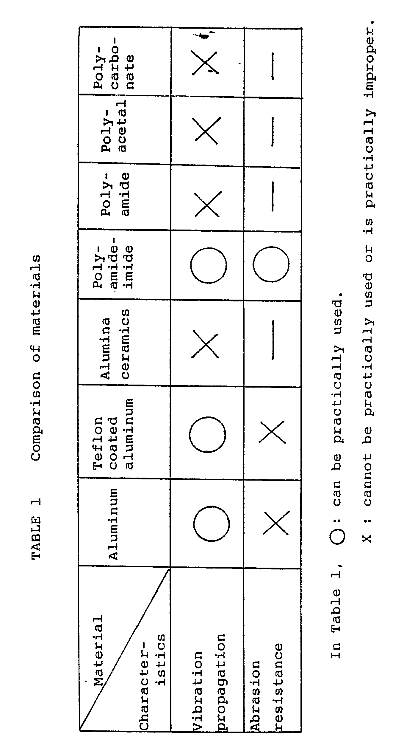
- aromatic polyamideimide Since the teflon coating film is easily scratched or peeled off due to the rubbing or the like, when it is used as a product, the aging stability cannot be guaranteed. On the other hand, it is considered that aromatic polyamideimide has a very good characteristic in terms of the abrasion resistance for glass. Therefore, it will be appreciated that aromatic polyamideimide is a proper material which can be actually used from the results of the experiments of the vibration propagation and the results of the abrasion resistance tests. (See Table 1.)
- titanium oxide, graphite, fluorocarbon resin, glass fiber, molybdenum disulfide, or the like may be also mixed.
- the vibration can be propagated without scratching the vibration propagating plate and the reduction of the pen tip itself due to the rubbing or the like is eliminated.
- the stable detection signal can be permanently derived.
- the high accurate coordinates input apparatus can be always realized.
- the writing feeling is also extremely improved.
- the pen tip can be cheaply manufactured as a product by the injection molding method or the like.
- a coordinates input apparatus in which a vibration input from a vibration pen having a piezoelectric transducer is detected by a plurality of vibration sensors attached to a vibration propagating plates such as an input tablet and the coordinates of this pen on the plate are detected.
- the tip of the vibration input pen is made of a material of a resin of the polyamideimide system such as thermoplastic poly amideimide or aromatic polyamideimide. With this material, a desired image can be smoothly input to the input tablet without scratching the glass surface thereof and the accurate coordinates can be detected.
Abstract
Description
- The present invention relates to a coordinates input apparatus and, more particularly, to a coordinates input apparatus in which a vibration input from a vibration pen is detected by a plurality of sensors attached to a vibration propagating plate and coordinates of the vibration pen on the vibration propagating plate are detected.
- Hitherto, as an apparatus for inputting hand-written characters, figures, or the like to a processing apparatus such as a computer, various kinds of coordinates input apparatuses using input pen, tablet, and the like have been known. In such a kind of apparatuses, image data consisting of input characters, figures, etc. is output to a display apparatus such as a CRT display or a recording apparatus such as a printer.
- The following various kinds of systems are known as a system to detect the coordinates on a tablet of this kind of apparatus.
- 1) A system in which a change in resistance value of a sheet material arranged so as to face a resistive film is detected.
- 2) A system in which the electromagnetic or electrostatic induction of a conductive sheet or the like which is arranged so as to face the tablet is detected.
- 3) A system in which the ultrasonic vibration which is propagated from an input pen to the tablet is detected.
- In the foregoing systems 1) and 2), it is difficult to form a transparent tablet since a resistive film or conductive film is used. On the other hand, in the system 3), since the tablet can be made of a transparent material such as acrylic plate, glass plate, or the like, it is possible to construct a coordinates input apparatus in which the input table is arranged so as to overlap a liquid crystal display device or the like and this apparatus can be used with such a feeling that an image is written on a paper and a good operating feeling is derived. In this case, a material such as aluminum having a good vibration propagating efficiency is generally used as a material of the tip of a vibration input pen to input an ultrasonic vibration onto the vibration propagating plate such as acrylic plate, glass plate, or the like.
- However, if aluminum is used as the material of the tip of the pen, although the vibration propagating efficiency is good, the vibration propagating plate made of acrylic plate, glass plate, or metal plate such as an aluminum plate which is used when transparency is not needed will be scratched, or the pen tip itself made of aluminum will be abraded.
- When the vibration propagating plate itself is scratched, it cannot be used as goods because of a bad outside appearance. On the other hand, there is a problem such that when the pen tip is abraded, the function as a vibration horn is lost and the detection waveform is disturbed, so that the coordinates cannot be detected at a high accuracy.
- It is an object of the present invention to provide a coordinates input apparatus of a high accuracy in which a vibration input from a vibration pen having vibration generating means is detected by a plurality of sensors attached to a vibration propagating plate and the coordinates of the vibration pen on the vibration propagating plate are detected, wherein by using a resin as a material of the tip of the vibration pen, the scratching on the vibration propagating plate is completely eliminated and the abrasion resistance of the resin is high, so that not only the life of the pen tip itself is remarkably prolonged but also the writing feeling can be improved and the stable detection wave-form can be obtained even when the pen is inclined.
-
- Fig. 1 is a diagram showing an arrangement of a coordinates input apparatus using the present invention;
- Fig. 2 is a diagram showing a structure of a vibration pen in Fig. 1;
- Fig. 3 is a block diagram showing an arrangement of a controller in Fig. 1;
- Fig. 4 is a waveform diagram showing a detection waveform for explaining the measurement of the distance between the vibration pen and the vibration sensor;
- Fig. 5 is a block diagram showing an arrangement of a waveform detecting circuit in Fig. 1;
- Fig. 6 is an explanatory diagram showing an arrangement of a vibration sensor;
- Fig. 7 is an explanatory diagram of the abrasion resistance test;
- Fig. 8 is a diagram showing the result of the abrasion resistance test; and
- Fig. 9 is a diagram showing a shape of a half-wave length resonant horn.
- The present invention will be described in detail hereinbelow on the basis of an embodiment shown in the drawings.
- Fig. 1 shows a structure of a coordinates input apparatus using the present invention. In the coordinates input apparatus of Fig. 1, coordinates are input by a
vibration pen 3 onto an input tablet consisting of avibration propagating plate 8 and in accordance with the input coordinates information, an input image is displayed on adisplay 11 consisting of a CRT arranged so as to be overlaid on the input tablet. - In the diagram, a
vibration propagating plate 8 is made of acrylic plate, glass plate, or the like and propagates the vibration which is input from thevibration pen 3 to threevibration sensors 6 attached to the upper surface in the corner portions of this plate. In this embodiment, the coordinates of thevibration pen 3 on thevibration propagating plate 8 are detected by measuring a propagating time of the ultrasonic vibration propagated from thevibration pen 3 to eachvibration sensor 6 through thevibration propagating plate 8. - The peripheral portion of the
vibration propagating plate 8 is supported by areflection preventing material 7 made of silicon rubber or the like in order to prevent that the vibration propagated from thevibration pen 3 is reflected by the peripheral portion and returned to the central portion. - The
vibration propagating plate 8 is arranged on thedisplay 11 such as a CRT (or LCD) which can display an image by dots and can dot display the image at the position which was traced by thevibration pen 3. That is, the dots of the input image are displayed at the position on thedisplay 11 corresponding to the detected coordinates of thevibration pen 3. The image consisting of elements such as points or lines which were input by thevibration pen 3 appears after the locus of the vibration pen as if it were written on a paper by the hand. - On the other hand, according to such a structure in the
display 11, it is also possible to use an input system in which a menu is displayed and a desired item on this menu is selected by the vibration pen, or a prompt is displayed and thevibration pen 3 is touched to a predetermined position, or the like. - The
vibration pen 3 to propagate the ultrasonic vibration to thevibration propagating plate 8 has therein avibrator 4 consisting of a piezoelectric transducer or the like. The ultrasonic vibration generated by thevibrator 4 is propagated to thevibration propagating plate 8 through ahorn portion 5 having a pointed tip. - Fig. 2 shows a structure of the
vibration pen 3. Thevibrator 4 assembled in thevibration pen 3 is driven by avibrator driver 2. A drive signal of thevibrator 4 is supplied as a low level pulse signal from a controller 1 in Fig. 1. This signal is amplified at a predetermined gain by thevibrator driver 2 which can be driven at a low impedance and, thereafter, it is applied to thevibrator 4. - The electrical drive signal is converted into the mechanical ultrasonic vibration by the
vibrator 4 and propagated to thevibration propagating plate 8 through thehorn portion 5. - A vibrating frequency of the
vibrator 4 is set to such a value that a plate wave can be generated from thevibration propagating plate 8 such as acrylic plate, glass plate, or the like. When the vibrator is driven, a vibrating mode such that thevibrator 4 mainly vibrates in the vertical direction in Fig. 2 for thevibration propagating plate 8 is selected. On the other hand, the vibration conversion can be efficiently performed by setting the vibrating frequency of thevibrator 4 to the resonant frequency of thevibrator 4. - The elastic wave which is propagated to the
vibration propagating plate 8 as mentioned above is the plate wave and has an advantage such that it is hardly influenced by a scratch, obstacle, or the like on the surface of thevibration propagating plate 8 as compared with the surface wave or the like. - Returning to Fig. 1, each of the
vibration sensors 6 attached to the corner portions of thevibration propagating plates 8 is also constructed by a mechanical/electrical converting device such as a piezoelectric transducer or the like. An output signal of each of the threevibration sensors 6 is input to asignal waveform detector 9 and converted into a detection signal which can be processed by the controller 1 at the post stage. The controller measures the vibration propagating time and detects the coordinates of the position of thevibration pen 3 on theplate 8. - The detected coordinates information of the
pen 3 is processed by the controller 1 in accordance with the output system by thedisplay 11. That is, the controller 1 controls the output operation of thedisplay 11 through adisplay driver 10 on the basis of the input coordinates information. - Fig. 3 shows an arrangement of the controller 1 in Fig. 1. Fig. 3 mainly shows an arrangement of the drive system of the
vibration pen 3 and the vibration detecting system by thevibrartion sensors 6. - A micro-computer 31 has therein an internal counter, a ROM, and a RAM. A
drive signal generator 32 generates drive pulses of a predetermined frequency to thevibrator driver 2 in Fig. 1 and is activated synchronously with a circuit to perform arithmetic operations of the coordinates by the micro-computer 31. - A count value of a
counter 33 is latched to alatch circuit 34 by the micro-computer 31. - On the other hand, the
signal waveform detector 9 outputs timing information of the detection signal to measure the vibration propagating time for detection of the coordinates and signal level information to detect the writing pressure on the basis of the outputs of thevibration sensors 6 as will be explained hereinafter. These timing and level information are respectively input to aninput port 35. - The timing signal generated from the
signal waveform detector 9 is input to theinput port 35 and compared with a count value in thelatch circuit 34 by adecision circuit 37. The result of the comparison is input to the micro-computer 31. That is, the vibration propagating time is expressed as a latch value of the output data of thecounter 33. The coordinates are calculated on the basis of the vibration propagating time value. - The output control process of the
display 11 is executed through an input/output (I/O)port 37. - Fig. 4 is a diagram for explain a waveform of a detection signal which is input to the
signal waveform detector 9 in Fig. 1 and the process to measure the vibration propagating time on the basis of this waveform. In Fig. 4, adrive signal pulse 41 is applied to thevibration pen 3. The ultrasonic vibration propagated to thevibration propagating plate 8 from thevibration pen 3 which had been driven by such a waveform passes through the inside of thevibration propagating plate 8 and is detected by thevibration sensors 6. - After the vibration progressed in the
plate 8 for a period of time tg corresponding to the distance to thevibration sensor 6, the vibration reaches thesensor 6.Reference numeral 42 in Fig. 4 denotes a signal waveform detected by thesensor 6. Since the dispersive wave is used as the plate wave in the embodiment, the relation between anenvelope 421 and aphase 422 of the detection waveform for the propagation distance in thevibration propagating plate 8 changes in accordance with the propagating distance during the propagation of the vibration. - A group velocity of the envelope assumes Vg and a phase velocity assumes Vp. The distance between the
pen 3 and thesensor 6 can be detected from the difference between the group velocity and the phase velocity. - When an attention is first paid to only the
envelope 421, the velocity is Vg. When a point on a special waveform, for instance, the peak is detected as shown at reference numeral 43 in Fig. 4, a distance d between thepen 3 and thesensor 6 can be obtained by
d = Vg·tg (1)
where, tg is a vibration propagating time. - Although this equation relates to one of the
vibration sensors 6, the distance between each of the other twovibration sensors 6 and thevibration pen 3 can be calculated by the same equation. - Further, to determine the coordinates values at a higher accuracy, the process based on the detection of a phase signal is executed. Assuming that a period of time from a special detection point of the
phase waveform 422 in Fig. 4, e.g., from the timing when the vibration is applied to the zero cross point after the passing of the peak point is tp, the distance between the sensor and the pen can be calculated by
d = n·λp + Vp.tp (2)
where, λp is a waveform of the elastic wave and n is an integer. - From the above equations (1) and (2), the integer n is obtained by
n = [(Vg·tg - Vp·tp)/λp+1/N] (3)
- N is a real number other than 0 and is set to a proper numerical value. For instance, when N = 2, if the wavelength lies within a range of ±1/2 wavelength, n can be determined.
- By substituting the value of n derived in this manner to the equation (2), the distance between the
pen 3 and thesensor 6 can be accurately measured. - The two vibration propagating times tg and tp shown in Fig. 4 are measured by the
signal waveform detector 9 in Fig. 1. Thesignal waveform detector 9 is constructed as shown in Fig. 5. To detect the writing pressure, the signal waveform detector in Fig. 5 also processes the level information of the output waveform of thevibration sensor 6 as will be explained hereinafter. - In Fig. 5, the output signal of the
sensor 6 is amplified to a predetermined level by apre-stage amplifier 51. The amplified signal is input to anenvelope detector 52 and only the envelope of the detection signal is extracted. The timing of the peak of the envelope extracted is detected by anenvelope peak detector 53. An envelope delay time detection signal Tg of a predetermined waveform is formed from the peak detection signal by a Tg-signal detector 54 consisting of a monostable multivibrator or the like and input to the controller 1. - On the other hand, a phase delay time detection signal Tp is formed by a comparator/
detector 58 from both of the Tg signal and the original signal delayed by adelay time adjuster 57. The Tp signal is input to the controller 1. - The above-mentioned circuit relates to one of the three
vibration sensors 6 and the same circuit is also provided for each of the other sensors. Now, assuming that the number of sensors is set to a general value of h, the h detection signals of the envelope delay times Tgl to Tgh and h detection signals of the phase delay times Tpl to Tph are input to the controller 1, respectively. - The controller 1 in Fig. 3 receives the signals Tgl to Tgh and the signals Tpl to Tph from the
input port 35 and takes the count value of thecounter 33 to thelatch circuit 34 by using each timing as a trigger. Since thecounter 33 is made operative synchronously with the driving of the vibration pen as mentioned above, the data indicative of the delay time of each of the envelope and phase are fetched to thelatch circuit 34. - As shown in Fig. 6, when three
vibration sensors 6 are arranged at three corner positions S₁ to S₃ on thevibration propagating plate 8, straight line distances d₁ to d₃ from a position P of thevibration pen 3 to the positions of thesensors 6 can be obtained by the processes which have already been described in Fig. 4. Further, the coordinates (x, y) of the position P of thepen 3 can be derived by the controller 1 on the basis of the straight line distances d₁ to d₃ by the theorem of three squares from the following equations.
x = X/2 + (d₁ + d₂)(d₁ - d₂)/2X (4)
y = Y/2 + (d₁ + d₃)(d₁ - d₃)/2Y (5)
where, X and Y denote distances along the X and Y a axes between thesensors 6 attached to the positions S₂ and S3 and the sensor attached to the origin (position S₁). - In this manner, the coordinates of the position of the
vibration pen 3 can be detected in a realtime manner. - According to the foregoing construction, since the ultrasonic vibration is propagated as the plate wave of the elastic wave to the
vibration propagating plate 8, the interference by a scratch and obstacle on thevibration propagating plate 8 can be reduced and the coordinates can be detected at a high accuracy. - Comparison and examination to determine the material of the
horn portion 5 will now be described hereinbelow. - In general, the horn has an advantage such that the vibration of the vibrator is enhanced. This horn is designed in accordance with the following resonant conditional equation so as to have a shape as illustrated in Fig. 9 (equation 6).

- Therefore, to obtain the efficient amplification at the front edge of the horn, it is necessary to keep the horn shape. On the other hand, even in the case where coordinates are input, the surface of the glass as a propagating material must not be scratched. Therefore, the following conditions are required as a material of the pen tip in which the horn is assembled.
- 1) The vibration of the vibrator can be propagated to the propagating material.
- 2) The abrasion resistance to the propagating material is good.
- 3) The propagating material is not scratched.
- An explanation will now be made with respect to the tests of the material which were performed to determine the material adapted to form the horn portion which can satisfy the above conditions.
- First, the examination of the material was made to see if the vibration of the vibrator can be input to a glass plate or not. Materials of aluminum, ceramics, and resin were examined in this case. The acoustic characteristics of aluminum are relatively similar to those of glass (acoustic impedance pc: pc of aluminum = 1.7 x 10⁷, pc of glass = 1.81 x 10⁷) and it is considered that aluminum has the good vibration propagating characteristics. Further, the material obtained by treating the surface of aluminum was also examined. In this test, alumina ceramics was used as ceramics. In general, a resin has a tendency such that the vibration is attenuated. Therefore, a hardness of resin was used as a parameter and an examination was made with regard to four kinds of polyamide, polyamideimide, polycarbonate, and polyacetal.
- A method of experiment to see if the vibration of the vibrator can be input to glass or not will now be explained hereinbelow.
- Horns of those materials were designed and made. The horns and piezoelectric transducer were bonded with a pressure by applying a weight of 500g thereto. The piezoelectric transducer was driven by pulses of 400 kHz. The plate wave elastic wave propagated through the glass plate was detected by the sensors and the detection signals were output. The output signals obtained at this time were measured and the resultant amplitudes were compared.
- Among those materials, the amplitude of the output detection signal waveform in the case of aluminum was the largest. 0n the other hand, almost the same amplitude was also derived even in the case of the material in which the surface of aluminum was treated. In the case of the material of teflon coated aluminum, the amplitude was reduced by about 10 to 15 % as compared with the amplitude of aluminum. Although the amplitude of polyamideimide was only about 30% of that of aluminum, the enough amplitude was derived when specifying a detection point of the detection signal waveform. On the other hand, an amplitude of the output signal was hardly derived with respect to each of alumina ceramics, polyamide, polycarbonate, and polyacetal.
- The abrasion resistance tests will now be explained.
- When the vibration of the vibrator assembled in the coordinates input pen is input to the vibration propagating material, the pen tip is abraded due to the rubbing with the propagating material. As mentioned above, in order to permanently keep the vibrating characteristics of the system of the horn and vibrator, it is unpreferable that the shape of the horn changes. That is, as a material of the pen tip, it is necessary to select such a material that the abrasion resistance to glass is high and it does not scratch the glass surface.
- As a method of experiments, horns were designed and formed by three kinds of materials such as aluminum, teflon coated aluminum, and aromatic polyamideimide and the abrasion resistance tests were performed in consideration of the results of experiments mentioned above. As shown in Fig. 7, a load weight F which is applied to the
vibration pen 3 from the upper portion thereof was set to 200 g weight and a rubbing speed V to glass was set to an average value of 72 mm/sec. Abrasion amounts when the speed was changed in a sine function manner were measured using the number of repetition times as a parameter. A running distance per cycle corresponds to about 2.5 characters in the case where a character "W" is written in a square of 1 cm². - Fig. 8 shows the results of the abrasion resistance tests. The abrasion amount of aluminum was large and reached the abrasion amount of 1mm or more by the repetition of about ten thousand times. In addition, the glass surface was scratched. Therefore, aluminum is improper as a material of the tip of the coordinates input pen of the digitizer. On the other hand, with respect to the material of anodized aluminum (alumite), although the abrasion resistance was slightly improved, it does not reach the level of the product. The abrasion resistance of teflon coated aluminum was remarkably improved. However, if the coated teflon film is broken, the abrasion amount rapidly increases. Since the teflon coating film is easily scratched or peeled off due to the rubbing or the like, when it is used as a product, the aging stability cannot be guaranteed. On the other hand, it is considered that aromatic polyamideimide has a very good characteristic in terms of the abrasion resistance for glass. Therefore, it will be appreciated that aromatic polyamideimide is a proper material which can be actually used from the results of the experiments of the vibration propagation and the results of the abrasion resistance tests. (See Table 1.)
- A few kinds of structural formulae of aromatic polyamideimide will now be shown below.

- Many other various structures are considered. On the other hand, as an additive and filling material, titanium oxide, graphite, fluorocarbon resin, glass fiber, molybdenum disulfide, or the like may be also mixed.
- As described above, by using aromatic polyamideimide as a material of the pen tip, the vibration can be propagated without scratching the vibration propagating plate and the reduction of the pen tip itself due to the rubbing or the like is eliminated. The stable detection signal can be permanently derived. Thus, the high accurate coordinates input apparatus can be always realized. On the other hand, the writing feeling is also extremely improved. Further, by use of aromatic polyamideimide, the pen tip can be cheaply manufactured as a product by the injection molding method or the like.
- As explained above, by use of aromatic poly amideimide as a material of the pen tip, a cheap coordinates input apparatus of a high accuracy and high durability can be provided.
- There is provided a coordinates input apparatus in which a vibration input from a vibration pen having a piezoelectric transducer is detected by a plurality of vibration sensors attached to a vibration propagating plates such as an input tablet and the coordinates of this pen on the plate are detected. The tip of the vibration input pen is made of a material of a resin of the polyamideimide system such as thermoplastic poly amideimide or aromatic polyamideimide. With this material, a desired image can be smoothly input to the input tablet without scratching the glass surface thereof and the accurate coordinates can be detected.
Claims (3)
wherein a resin of a polyamideimide system is used as a material of a tip of said vibration input pen.
Applications Claiming Priority (2)
| Application Number | Priority Date | Filing Date | Title |
|---|---|---|---|
| JP27396387A JPH0746301B2 (en) | 1987-10-28 | 1987-10-28 | Coordinate input device |
| JP273963/87 | 1987-10-28 |
Publications (3)
| Publication Number | Publication Date |
|---|---|
| EP0314149A2 true EP0314149A2 (en) | 1989-05-03 |
| EP0314149A3 EP0314149A3 (en) | 1990-08-22 |
| EP0314149B1 EP0314149B1 (en) | 1993-09-22 |
Family
ID=17535020
Family Applications (1)
| Application Number | Title | Priority Date | Filing Date |
|---|---|---|---|
| EP88117952A Expired - Lifetime EP0314149B1 (en) | 1987-10-28 | 1988-10-27 | Coordinates input apparatus |
Country Status (4)
| Country | Link |
|---|---|
| US (1) | US5726686A (en) |
| EP (1) | EP0314149B1 (en) |
| JP (1) | JPH0746301B2 (en) |
| DE (1) | DE3884335T2 (en) |
Families Citing this family (23)
| Publication number | Priority date | Publication date | Assignee | Title |
|---|---|---|---|---|
| JPH03137970A (en) * | 1989-10-24 | 1991-06-12 | Canon Inc | Input pen for ultrasonic digitizer |
| US6563493B2 (en) | 1997-06-30 | 2003-05-13 | Canon Kabushiki Kaisha | Molded article of pen tip of input pen for coordinate input apparatus, method of molding pen tip and mold therefor |
| US6384814B1 (en) | 1998-02-16 | 2002-05-07 | Canon Kabushiki Kaisha | Input pen |
| JP2001249761A (en) * | 2000-03-03 | 2001-09-14 | Axiom Co Ltd | System for judging writing and writing tool for judging writing and method for judging writing |
| GB0114455D0 (en) * | 2001-06-14 | 2001-08-08 | Koninkl Philips Electronics Nv | Data inut system |
| US20060139339A1 (en) * | 2004-12-29 | 2006-06-29 | Pechman Robert J | Touch location determination using vibration wave packet dispersion |
| US7538894B2 (en) | 2005-04-15 | 2009-05-26 | Canon Kabushiki Kaisha | Coordinate input apparatus, control method thereof, and program |
| JP4455392B2 (en) * | 2005-04-15 | 2010-04-21 | キヤノン株式会社 | Coordinate input device, control method therefor, and program |
| US7683890B2 (en) * | 2005-04-28 | 2010-03-23 | 3M Innovative Properties Company | Touch location determination using bending mode sensors and multiple detection techniques |
| JP2008078628A (en) * | 2006-08-25 | 2008-04-03 | Canon Inc | Electronic module, and manufacturing method thereof |
| JP2010521015A (en) * | 2006-10-05 | 2010-06-17 | ペガサス テクノロジーズ リミテッド | DIGITAL PEN SYSTEM, TRANSMITTER DEVICE, RECEIVER DEVICE, AND THEIR MANUFACTURING METHOD AND USING METHOD |
| JP5460341B2 (en) * | 2010-01-06 | 2014-04-02 | キヤノン株式会社 | Three-dimensional measuring apparatus and control method thereof |
| JP5489886B2 (en) | 2010-06-30 | 2014-05-14 | キヤノン株式会社 | Coordinate input device, light receiving device in the device, and manufacturing method thereof |
| JP5725774B2 (en) | 2010-09-13 | 2015-05-27 | キヤノン株式会社 | Coordinate input device and coordinate input method |
| CN102169384B (en) * | 2010-12-21 | 2016-12-07 | 合肥海尔洗衣机有限公司 | A kind of method of toch control |
| JP5973849B2 (en) | 2012-03-08 | 2016-08-23 | キヤノン株式会社 | Coordinate input device and sensor bar used for coordinate input device |
| JP5875445B2 (en) | 2012-03-30 | 2016-03-02 | キヤノン株式会社 | Coordinate input device |
| JP5986426B2 (en) | 2012-05-24 | 2016-09-06 | キヤノン株式会社 | Sound processing apparatus and sound processing method |
| JP6049334B2 (en) | 2012-07-12 | 2016-12-21 | キヤノン株式会社 | Detection apparatus, detection method, and program |
| JP6031293B2 (en) | 2012-08-03 | 2016-11-24 | キヤノン株式会社 | Coordinate input device, control method therefor, and program |
| JP6021531B2 (en) | 2012-08-31 | 2016-11-09 | キヤノン株式会社 | Coordinate input device, control method therefor, and program |
| US11358290B2 (en) | 2017-10-19 | 2022-06-14 | Canon Kabushiki Kaisha | Control apparatus, robot system, method for operating control apparatus, and storage medium |
| JP2019084601A (en) | 2017-11-02 | 2019-06-06 | キヤノン株式会社 | Information processor, gripping system and information processing method |
Citations (2)
| Publication number | Priority date | Publication date | Assignee | Title |
|---|---|---|---|---|
| EP0107922A1 (en) * | 1982-09-30 | 1984-05-09 | New York Institute Of Technology | Graphical data apparatus |
| FR2575281A1 (en) * | 1984-12-21 | 1986-06-27 | Inf Milit Spatiale Aeronaut | Elastic wave position sensor |
Family Cites Families (8)
| Publication number | Priority date | Publication date | Assignee | Title |
|---|---|---|---|---|
| JPS6021193B2 (en) * | 1976-12-14 | 1985-05-25 | ダイキン工業株式会社 | Fluororesin coating composition |
| FR2535387B1 (en) * | 1982-10-29 | 1985-06-21 | Stoltz Gerard | FOLDABLE LADDER LADDER |
| KR920002254B1 (en) * | 1983-12-05 | 1992-03-20 | 닛신 고오기 가부시끼가이샤 | Optical mouse |
| JPS60153537A (en) * | 1984-01-20 | 1985-08-13 | Wacom Co Ltd | Coordinate input device having display |
| DE3506309A1 (en) * | 1984-02-22 | 1985-08-22 | Summagraphics Corp | Electrooptical mouse |
| DE3779019D1 (en) * | 1986-06-27 | 1992-06-17 | Canon Kk | COORDINATE INPUT DEVICE. |
| JP2658039B2 (en) * | 1987-03-20 | 1997-09-30 | キヤノン株式会社 | Information processing device |
| US4853496A (en) * | 1987-03-27 | 1989-08-01 | Canon Kabushiki Kaisha | Acoustic coordinate input device using a roughened surface to attenuate the surface wave component |
-
1987
- 1987-10-28 JP JP27396387A patent/JPH0746301B2/en not_active Expired - Fee Related
-
1988
- 1988-10-27 EP EP88117952A patent/EP0314149B1/en not_active Expired - Lifetime
- 1988-10-27 DE DE88117952T patent/DE3884335T2/en not_active Expired - Lifetime
-
1993
- 1993-10-04 US US08/131,914 patent/US5726686A/en not_active Expired - Lifetime
Patent Citations (2)
| Publication number | Priority date | Publication date | Assignee | Title |
|---|---|---|---|---|
| EP0107922A1 (en) * | 1982-09-30 | 1984-05-09 | New York Institute Of Technology | Graphical data apparatus |
| FR2575281A1 (en) * | 1984-12-21 | 1986-06-27 | Inf Milit Spatiale Aeronaut | Elastic wave position sensor |
Also Published As
| Publication number | Publication date |
|---|---|
| DE3884335T2 (en) | 1994-02-24 |
| EP0314149A3 (en) | 1990-08-22 |
| US5726686A (en) | 1998-03-10 |
| EP0314149B1 (en) | 1993-09-22 |
| JPH0746301B2 (en) | 1995-05-17 |
| DE3884335D1 (en) | 1993-10-28 |
| JPH01114924A (en) | 1989-05-08 |
Similar Documents
| Publication | Publication Date | Title |
|---|---|---|
| EP0314149B1 (en) | Coordinates input apparatus | |
| EP0364983B1 (en) | Coordinate input apparatus | |
| US5017913A (en) | Coordinates input apparatus | |
| US5142106A (en) | Coordinates input apparatus | |
| EP0296569B1 (en) | Coordinates input apparatus | |
| JP3053262B2 (en) | Coordinate input device and method | |
| US5097415A (en) | Coordinates input apparatus | |
| EP0169538A2 (en) | Tablet type coordinate input apparatus using elastic waves | |
| US6288711B1 (en) | Coordinate input apparatus, method of controlling same and computer-readable memory | |
| US4897510A (en) | Coordinate inputting device including an electrode to reduce noise components | |
| EP0284048A2 (en) | Coordinates input apparatus | |
| US4853496A (en) | Acoustic coordinate input device using a roughened surface to attenuate the surface wave component | |
| US5748182A (en) | Coordinates input apparatus connected to image processing system | |
| JPS63245711A (en) | Coordinate input device | |
| JPH01112418A (en) | Coordinate input device | |
| JPS63239518A (en) | Coordinates input device | |
| JP2537542B2 (en) | Coordinate input device | |
| JP2654396B2 (en) | Coordinate input device | |
| JP2654397B2 (en) | Coordinate input device | |
| JPH01161424A (en) | Coordinate input device | |
| JPS63136127A (en) | Coordinate input device | |
| JPH02130617A (en) | Coordinate input device | |
| JPH06149455A (en) | Coordinate input device | |
| JPS63136126A (en) | Coordinate input device | |
| JPS63103317A (en) | Coordinate input device |
Legal Events
| Date | Code | Title | Description |
|---|---|---|---|
| PUAI | Public reference made under article 153(3) epc to a published international application that has entered the european phase |
Free format text: ORIGINAL CODE: 0009012 |
|
| AK | Designated contracting states |
Kind code of ref document: A2 Designated state(s): DE FR GB IT NL |
|
| PUAL | Search report despatched |
Free format text: ORIGINAL CODE: 0009013 |
|
| AK | Designated contracting states |
Kind code of ref document: A3 Designated state(s): DE FR GB IT NL |
|
| 17P | Request for examination filed |
Effective date: 19901221 |
|
| 17Q | First examination report despatched |
Effective date: 19921204 |
|
| GRAA | (expected) grant |
Free format text: ORIGINAL CODE: 0009210 |
|
| AK | Designated contracting states |
Kind code of ref document: B1 Designated state(s): DE FR GB IT NL |
|
| REF | Corresponds to: |
Ref document number: 3884335 Country of ref document: DE Date of ref document: 19931028 |
|
| ITTA | It: last paid annual fee | ||
| ITF | It: translation for a ep patent filed |
Owner name: SOCIETA' ITALIANA BREVETTI S.P.A. |
|
| ET | Fr: translation filed | ||
| PLBE | No opposition filed within time limit |
Free format text: ORIGINAL CODE: 0009261 |
|
| STAA | Information on the status of an ep patent application or granted ep patent |
Free format text: STATUS: NO OPPOSITION FILED WITHIN TIME LIMIT |
|
| 26N | No opposition filed | ||
| REG | Reference to a national code |
Ref country code: GB Ref legal event code: IF02 |
|
| PGFP | Annual fee paid to national office [announced via postgrant information from national office to epo] |
Ref country code: NL Payment date: 20041003 Year of fee payment: 17 |
|
| PGFP | Annual fee paid to national office [announced via postgrant information from national office to epo] |
Ref country code: FR Payment date: 20041008 Year of fee payment: 17 |
|
| PGFP | Annual fee paid to national office [announced via postgrant information from national office to epo] |
Ref country code: GB Payment date: 20041027 Year of fee payment: 17 |
|
| PG25 | Lapsed in a contracting state [announced via postgrant information from national office to epo] |
Ref country code: IT Free format text: LAPSE BECAUSE OF NON-PAYMENT OF DUE FEES;WARNING: LAPSES OF ITALIAN PATENTS WITH EFFECTIVE DATE BEFORE 2007 MAY HAVE OCCURRED AT ANY TIME BEFORE 2007. THE CORRECT EFFECTIVE DATE MAY BE DIFFERENT FROM THE ONE RECORDED. Effective date: 20051027 Ref country code: GB Free format text: LAPSE BECAUSE OF NON-PAYMENT OF DUE FEES Effective date: 20051027 |
|
| PG25 | Lapsed in a contracting state [announced via postgrant information from national office to epo] |
Ref country code: NL Free format text: LAPSE BECAUSE OF NON-PAYMENT OF DUE FEES Effective date: 20060501 |
|
| GBPC | Gb: european patent ceased through non-payment of renewal fee |
Effective date: 20051027 |
|
| PG25 | Lapsed in a contracting state [announced via postgrant information from national office to epo] |
Ref country code: FR Free format text: LAPSE BECAUSE OF NON-PAYMENT OF DUE FEES Effective date: 20060630 |
|
| NLV4 | Nl: lapsed or anulled due to non-payment of the annual fee |
Effective date: 20060501 |
|
| REG | Reference to a national code |
Ref country code: FR Ref legal event code: ST Effective date: 20060630 |
|
| PGFP | Annual fee paid to national office [announced via postgrant information from national office to epo] |
Ref country code: DE Payment date: 20071025 Year of fee payment: 20 |