EP0313362A2 - Low-section pneumatic radial tire - Google Patents
Low-section pneumatic radial tire Download PDFInfo
- Publication number
- EP0313362A2 EP0313362A2 EP88309882A EP88309882A EP0313362A2 EP 0313362 A2 EP0313362 A2 EP 0313362A2 EP 88309882 A EP88309882 A EP 88309882A EP 88309882 A EP88309882 A EP 88309882A EP 0313362 A2 EP0313362 A2 EP 0313362A2
- Authority
- EP
- European Patent Office
- Prior art keywords
- tread
- layers
- auxiliary
- auxiliary layers
- tire
- Prior art date
- Legal status (The legal status is an assumption and is not a legal conclusion. Google has not performed a legal analysis and makes no representation as to the accuracy of the status listed.)
- Granted
Links
Images


Classifications
-
- B—PERFORMING OPERATIONS; TRANSPORTING
- B60—VEHICLES IN GENERAL
- B60C—VEHICLE TYRES; TYRE INFLATION; TYRE CHANGING; CONNECTING VALVES TO INFLATABLE ELASTIC BODIES IN GENERAL; DEVICES OR ARRANGEMENTS RELATED TO TYRES
- B60C9/00—Reinforcements or ply arrangement of pneumatic tyres
- B60C9/18—Structure or arrangement of belts or breakers, crown-reinforcing or cushioning layers
- B60C9/26—Folded plies
-
- B—PERFORMING OPERATIONS; TRANSPORTING
- B60—VEHICLES IN GENERAL
- B60C—VEHICLE TYRES; TYRE INFLATION; TYRE CHANGING; CONNECTING VALVES TO INFLATABLE ELASTIC BODIES IN GENERAL; DEVICES OR ARRANGEMENTS RELATED TO TYRES
- B60C9/00—Reinforcements or ply arrangement of pneumatic tyres
- B60C9/18—Structure or arrangement of belts or breakers, crown-reinforcing or cushioning layers
- B60C9/20—Structure or arrangement of belts or breakers, crown-reinforcing or cushioning layers built-up from rubberised plies each having all cords arranged substantially parallel
- B60C9/2003—Structure or arrangement of belts or breakers, crown-reinforcing or cushioning layers built-up from rubberised plies each having all cords arranged substantially parallel characterised by the materials of the belt cords
- B60C9/2009—Structure or arrangement of belts or breakers, crown-reinforcing or cushioning layers built-up from rubberised plies each having all cords arranged substantially parallel characterised by the materials of the belt cords comprising plies of different materials
-
- B—PERFORMING OPERATIONS; TRANSPORTING
- B60—VEHICLES IN GENERAL
- B60C—VEHICLE TYRES; TYRE INFLATION; TYRE CHANGING; CONNECTING VALVES TO INFLATABLE ELASTIC BODIES IN GENERAL; DEVICES OR ARRANGEMENTS RELATED TO TYRES
- B60C9/00—Reinforcements or ply arrangement of pneumatic tyres
- B60C9/18—Structure or arrangement of belts or breakers, crown-reinforcing or cushioning layers
- B60C9/20—Structure or arrangement of belts or breakers, crown-reinforcing or cushioning layers built-up from rubberised plies each having all cords arranged substantially parallel
- B60C9/22—Structure or arrangement of belts or breakers, crown-reinforcing or cushioning layers built-up from rubberised plies each having all cords arranged substantially parallel the plies being arranged with all cords disposed along the circumference of the tyre
- B60C9/2204—Structure or arrangement of belts or breakers, crown-reinforcing or cushioning layers built-up from rubberised plies each having all cords arranged substantially parallel the plies being arranged with all cords disposed along the circumference of the tyre obtained by circumferentially narrow strip winding
Definitions
- the present invention relates to an improvement in a low-section pneumatic radial tire, and more specifically to an improvement in high-speed durability of a low-section pneumatic radial tire.
- low-section (wide-tread) pneumatic radial tires with an aspect ratio (a ratio of section height to maximum width of a tire) of 0.3 to 0.6 are called ultrahigh performance tires, and suitable for use in high-speed vehicle travel.
- Fig. 1 is a cross-sectional view for assistance in explaining an example of prior-art low-section pneumatic radial tires.
- the tire is formed with a cylindrical tread T extending between two tire sidewalls S which extend radially inward.
- the tire is roughly composed of a radial carcass 1 for reinforcing the tire from one sidewall S, through the tread T, to the other sidewall S, and a belt structure B having a width substantially the same as that of the tread T and disposed between the tread T and the radial carcass 1.
- the tread T there are formed at least six circumferentially extending grooves made up of a pair of first innermost circumferential grooves 4A formed near the tire equatorial plane O, a pair of second intermediate circumferential grooves 4B formed between the first inner most grooves 4A and both tread ends 6, and a pair of third outermost circumferential grooves 4C formed near the tread ends 6.
- the tread T is divided into at least 7 lands including a first central land portion 5A, a pair of second intermediate land portions 5B, and a pair of third intermediate land portions 5C, and a pair of fourth outermost land portions 5D.
- the belt structure B is composed of at least two layers 2 formed by arranging inextensible metallic cords at a small inclination angle with respect to the tire equatorial plane O so that the cords of two different layers are laid one upon another in intersectional relationship to each other and three auxiliary layers formed by arranging heat-shrinkable fiber cords on the outer circumferential surface of the belt layers 2 substantially in parallel to the tire equatorial plane O.
- auxiliary layers 3 of the belt structure B is composed of a first auxiliary layer 3A extending over the entire width of the tire read T, a pair of second auxiliary layers 3B arranged at both side ends of the tire tread T in such away that the inner end of the layer 3B extends beyond under the outermost groove 4C, and a pair of third auxiliary layer 3C arranged at both side ends of the tire read T in such a way that the inner end of the layer 3C extends to a position a little outward away from under the outermost groove 4C.
- auxiliary layers 3 serve to prevent the belt layers 2 from being expanded radially outward due to centrifugal force generated when the tire is rotating at high rotating speed, in order to improve the tire performance (durability) at high speed.
- a low-section pneumatic radial tire including (a) a cylindrical tread formed with two sidewalls and at least four circumferential grooves, for dividing the tread into at least five land portions; (b) a radial carcass formed by arranging organic fiber cords at substantially right angles with respect to the tire circumferential direction, for reinforcing the sidewalls through the cylindrical tread; (c) a belt structure disposed between the cylindrical tread and the radial carcass and composed of at least two belt layers formed by arranging inextensible metallic cords at a small inclination angle with respect to a tire equatorial plane so that the cords of different belt layers are laid one upon another in intersectional relationship to each other, the present invention is characterized in that the auxiliary layers comprises (1) a first auxiliary layer extending substantially all over the belt layers; (2) a pair of second auxiliary layers formed on said first auxiliary layer; and (3) a pair of third auxiliary layers formed on said second auxiliary layer; said second and third
- the inventors have studied the reason why the belt layers are separated or the sidewalls are broken into damage in particular after the tire has been worn off to some extent, and obtained the following results.
- the central tread area of the tire is first worn off with specific wear characteristics, so that the central tread rubber mass is reduced.
- the tread rubber mass increases on both tread side ends into unbalanced condition, the tread rubbers on both the tread side ends are expanded radially outward due to great centrifugal forces applied at both tread side ends, so that distortion is concentrated to both the tread side ends and therefore heat is generated mainly on both the tread side ends when the tire is rotating at high speed.
- great shearing strains are produced at the carcass ends or at the tire sidewalls and further the elasticity of the carcass is small, a separation trouble at the carcass side ends occurs and further the sidewalls are expanded into breakage.
- the tire is first mainly worn off at the central tread area, but not worn off so much at both the tread side end areas. Therefore, after the radial tire has been worn off to some extent, both the tread side ends of less abrasion tend to expand radially outward when the tire is rotated at an ultrahigh speed, so that the belt layers may be separated at both the belt side ends, or the sidewalls are broken into damaged.
- the first feature of the radial tire according to the present invention is to provide at least two auxiliary layers on both tread outer areas in such a way that an axially inner end of each of the two auxiliary layers extends to or beyond under an axially outermost circumferential groove formed on said cylindrical tread.
- the circumferential rigidity of the belt structure is increased by four auxiliary layers superposed in step fashion extending from tread center to tread end. In a second embodiment of the present invention, the circumferential rigidity of the belt structure is increased by three auxiliary layers superposed in step fashion extending from tread end to read center.
- the second feature of the radial tire according to the present invention is to form these auxiliary layers by winding a ribbon including at least two heat-shrinkable fiber cords coated with a coating rubber in spiral fashion on the circumferential surface of the belt layers. Therefore, it is possible to securely form auxiliary layers resistant against centrifugal force generated when the tire is rotated at ultrahigh speed.
- Fig. 2(A) shows a first embodiment of the present invention.
- the low-section pneumatic radial tire of the present invention includes a pair of annular bead cores (not shown), and a radial carcass 10 extending between the two bead cores in toroidal shape.
- This radial carcass is composed of a single or plural plies formed by arranging organic fiber cords (e.g. rayon, polyester, nylon, etc.) at substantially right angles with respect to the tire circumferential direction.
- both the side end portions of the carcass ply are wrapped around the head coves from the axially inner side to the axially outer side. Further, two spaces formed between these wrapped ply ends and the radial carcass are filled with a hard rubber filler, as is well known.
- the tire is formed with a cylindrical tread T extending between two tire sidewalls S which extend radially inward.
- the tire is roughly composed of a radial carcass 10 for reinforcing the tire from one sidewall S, through the tread T, to the other sidewall S and a belt structure B having a width substantially the same as that of the tread and disposed between the tread T and the radial carcass 10.
- the tread T there are formed six circumferentially extending grooves made up of a pair of first innermost circumferential grooves 40A located near the tire equatorial plane 0, a pair of second intermediate circumferential grooves 40B located between the first innermost grooves 40A and both tread side ends 60, and a pair of third outermost circumferential grooves 40C located near the tread side ends 60.
- the tread T is divided into at least 7 land portions including a first central land portion 50A, a pair of second intermediate land portions 50B, and a pair of third intermediate land portions 50C, and a pair of fourth outermost land portions 50D.
- These land portions are further divided into a number of blocks by a plurality of lateral grooves extending at inclination angles with respect to the circumferential grooves, as is well known.
- a belt structure B is composed of at least two layers 20 formed by arranging inextensible metallic cords at a small inclination angle (about 30 to 50 degrees) with respect to the tire equatorial plane O so that the cords of different layers are laid one upon another in intersectional relationship to each other and a plurality of auxiliary layers 30, 31, 32 and 33 formed by arranging heat-shrinkable organic fiber cords on the outer circumferential surface of the belt layers 20 substantially in parallel to the tire equatorial plane O.
- the auxiliary layers are composed of a first auxiliary layer 30 extending over the tread between the two tread side ends 60 with a width a little wider than that of the belt layers 20; a pair of second auxiliary layers 31 extending between the second intermediate land portion 50B and the tread side end 60, respectively; a pair of third auxiliary layers 32 extending between the third intermediate land portion 50C and the tread side end 60, respectively; and a pair of fourth auxiliary layers 33 extending between the fourth outermost land portion 50D and the tread side end 60, respectively.
- the first central land portion 50A is reinforced by the first auxiliary layer 30 extending over the tread T;
- the second intermediate land portions 50B are reinforced by the first and the second auxiliary layers 30 and 31;
- the third intermediate land portions 50C are reinforced by the first, second and third auxiliary layers 30, 31 and 32;
- the fourth outermost land portions 50D are reinforced by the first, second, third and fourth auxiliary layers 30, 31, 32 and 33. Therefore, the rigidity of the belt structure B in the tire circumferential direction increases in stepped fashion extending from the tread center to the tread side end, respectively.
- each of these auxiliary layers 30, 31, 32 and 33 is located at the axially outer side end of the fourth outermost land portions 50D, and the axially inner end of each of the auxiliary layers 31, 32 and 33 is preferably located at a position 5 cm or more inward away from the axially inner end of the circumferential grooves 40B and 40C, that is, at a position substantially near the middle of the land portions 50B and 50C.
- the inner end of each of the auxiliary layers is located within each block formed on the tire tread.
- the feature of the first embodiment is to provide the plural auxiliary layers superposed in step fashion extending from the tread center to the tread end, respectively.
- auxiliary layers By arranging the auxiliary layers as described above, it is possible to improve the hoop effect and the belt layer rigidity at both tread side end areas (in particular, the outermost land portions 50D), while decreasing defective tires in manufacturing process. Further, this arrangement of the auxiliary layers serves to prevent the auxiliary layers from being separated toward the axially inward direction of the tire.
- Fig. 2(B) is an illustration for assistance in explaining the first method of winding the auxiliary layers 30, 31, 32 and 33 according to the first embodiment.
- Each auxiliary layer can be formed by winding a ribbon 100 (shown in Fig. 2D) in spiral fashion in the tire circumferential direction (in parallel to the tire equatorial plane) on the belt layers 20.
- the ribbon 100 is formed by reinforcing a coating rubber 112 by 2 to 15 heat-shrinkable nylon cords 111 arranged in parallel to each other, as shown in Fig. 2(D).
- the ribbon 100 in order to form the first and second auxiliary layers 30 and 31, the ribbon 100 is first wound beginning from a winding start point 70 in the axially leftward direction as shown by arrow 90 to the axially outer end of the tire.
- the ribbon 100 is then wound in the opposite direction as shown by arrow 91 to another axially outermost end of the auxiliary layers.
- the ribbon 100 is returned again in the leftward direction as shown by arrow 92 to a winding end point 71 mirror symmetrical with respect to the winding start point 70 about the tire equatorial plane.
- the ribbon 100 is first wound beginning from a winding start point 73 in the axially outward direction as shown by arrow 94 to the axially outer end of the auxiliary layers.
- the ribbon 100 is then wound in the opposite direction to a winding end point 75 a little outward away from the start point 73.
- Fig. 2(C) is an illustration for assistance in explaining the second method of winding the auxiliary layers 30, 31, 32 and 33 according to the present invention.
- each auxiliary layer can be formed by winding the ribbon 100 in spiral fashion in the circumferential direction on the belt layer 20.
- the ribbon 100 is wound beginning from a winding start point 76 to a winding end point 77 in the direction as shown by arrow 95.
- the above winding direction can of course be reversed in the opposite direction from the point 77 to the point 76.
- the ribbon 100 is first wound beginning from a winding start point 80 in the axially outward direction as shown by arrow 96 to the axially outer end of the tire.
- the ribbon 100 is then wound in the opposite direction to a winding end point 81 a little outward away from the start point 80 in the direction as shown by arrow 98.
- the ribbon 100 is wound beginning from a winding start point 83 to a winding end point 85.
- the above winding direction can of course be reversed from the point 85 to the point 83.
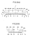
- Fig. 3(A) shows a second embodiment of the present invention.
- the tire is formed with a cylindrical tread portion T extending between two tire sidewalls which extend radially inward.
- the tire is roughly composed of a radial carcass 10 and a belt structure B having a width substantially the same as that of the tread and disposed between the tread T and the radial carcass 10.
- the tread T there are formed at least four circumferentially extending circumferential grooves arranged at roughly regular intervals on the tread between the two tread side ends 60.
- the circumferential grooves are made up of a pair of first inner circumferential grooves 40A located near the tire equatorial plane O, and a pair of second outer circumferential grooves 40B located near the tread side ends 60.
- the tread T is divided into 5 land portions including a first central land portion 50A, a pair of second intermediate land portions 50B, and a pair of third outer land portions 50D.
- These land portions are further divided into a number of blocks by a plurality of lateral grooves extending at inclination angles with respect to the circumferential grooves, as is well known.
- a belt structure B is composed of at least two layers 20 formed by arranging inextensible metallic cords at a small inclination angle with respect to the tire equatoria] plane O and a plurality of auxiliary layers 30, 31 and 32 formed by arranging heat-shrinkable organic fiber cords on the outer circumferential surface of the belt layers 20 substantially in parallel to the tire equatorial plane O.
- the auxiliary layers are composed of a first auxiliary layer 30 extending over the tread between the two tread side ends 60 with a width a little wider than that of the belt layers 20, a pair of second auxiliary layers 31 extending from the tread side end to a position just under the bottom of the second outer circumferential groove 40B, respectively, and a pair of third auxiliary layers 32 extending from the tread side end to a position a little axially inward away from under the groove 40B, respectively. That is, the feature of the present embodiment is to extend the third (radially outward) auxiliary layers 32 a little inward away from the axially inner end of the second auxiliary layers 31. In this second embodiment, it is also possible to extend the axially inward ends of the second and third auxiliary layers 31 and 32 to or beyond under the first inner circumferential groove 40A, respectively.
- the feature of the second embodiment is to provide the plural auxiliary layers superposed in step fashion extending from the tread end to the tread center, respectively. Further, in this second embodiment, it is also possible to provide a fourth auxiliary layer (not shown) in the out most land portion 50D, respectively.
- Fig. 3(B) is an illustration for assistance in explaining the first method of winding the auxiliary layers 30, 31 and 32 according to the second embodiment.
- the ribbon 100 is first wound beginning from a winding start point 70A in the axially outward direction as shown by arrow 90A to the axially outermost end of the auxiliary layers.
- the ribbon 100 is then wound in the opposite direction as shown by arrow 91A to another axially outermost end of the auxiliary layers.
- the ribbon 100 is returned in the original direction as shown by arrow 92A to a winding end point 71A mirror symmetrical to the start point 70A about the tire equatorial plane.
- the ribbon 100 is wound beginning from a winding start point 83A to a winding end point 85A, respectively.
- the above winding direction can of course be reversed from the point 85A to the point 83A.
- Fig. 2(A) Radial tires as shown in Fig. 2(A) were manufactured.
- the tire size was 255140 ZR 17.
- the radial carcass 10 was formed by arranging rayon cords 1650 d/2.
- the belt layers 20 were formed by arranging 0.23 x 1 x 5 steel cords at an inclination angle 25 degrees with respect to the tire circumferential direction in such a way that cords of different belt layers were laid one upon another so as to intersect each other.
- the first auxiliary layer 30 was formed by arranging 1260 d/2 nylon cords into a single layer in parallel to the tire circumference so as to cover the entire width of the belt layers 20.
- the second auxiliary layers 31 were formed by arranging the same nylon cords between the tread side ends and the second intermediate land portion 50B so that the axially inner end thereof extends to the middle of the land portion 50B.
- the third auxiliary layers 32 were formed by arranging the same nylon cords between the tread side ends and the third intermediate land portion 50C so that the axially inner end thereof extends to the middle of the land portion 50C.
- the fourth auxiliary layers 33 were formed by arranging the same nylon cords at the third outer land portions 50D. That is, four auxiliary layers were superposed at the outer land portions 50D.
- the structure except the above was substantially the same as in the ordinary radial tire.
- radial tires as shown in Fig. 1 were manufactured, in which two auxiliary layers are arranged being superposed at the outer land portion 5D.
- the structure except the above was substantially the same as in the ordinary radial tire.
- the durability indices of the invention tires were 125, where that of the prior-art tires were set to 100.
- the circumferential rigidity of the belt structure is increased in stepped fashion from the tread center to tread ends or vice versa in such a way that the maximum rigidity can be obtained on both the tread side ends due to the hoop effect of these auxiliary layers, it is possible to effectively prevent the belt layers from being separated at the belt side end portions and the tire sidewalls from being expanded into breakage, in particular when the tire has been worn off to some extent, thus improving the high-speed durability.
Abstract
Description
- The present invention relates to an improvement in a low-section pneumatic radial tire, and more specifically to an improvement in high-speed durability of a low-section pneumatic radial tire.
- In general, low-section (wide-tread) pneumatic radial tires with an aspect ratio (a ratio of section height to maximum width of a tire) of 0.3 to 0.6 are called ultrahigh performance tires, and suitable for use in high-speed vehicle travel.
- Fig. 1 is a cross-sectional view for assistance in explaining an example of prior-art low-section pneumatic radial tires. In the drawing, the tire is formed with a cylindrical tread T extending between two tire sidewalls S which extend radially inward. The tire is roughly composed of a
radial carcass 1 for reinforcing the tire from one sidewall S, through the tread T, to the other sidewall S, and a belt structure B having a width substantially the same as that of the tread T and disposed between the tread T and theradial carcass 1. - On the tread T, there are formed at least six circumferentially extending grooves made up of a pair of first innermost
circumferential grooves 4A formed near the tire equatorial plane O, a pair of second intermediatecircumferential grooves 4B formed between the first innermost grooves 4A and bothtread ends 6, and a pair of third outermostcircumferential grooves 4C formed near thetread ends 6. By these sixcircumferential grooves central land portion 5A, a pair of secondintermediate land portions 5B, and a pair of thirdintermediate land portions 5C, and a pair of fourthoutermost land portions 5D. - The belt structure B is composed of at least two
layers 2 formed by arranging inextensible metallic cords at a small inclination angle with respect to the tire equatorial plane O so that the cords of two different layers are laid one upon another in intersectional relationship to each other and three auxiliary layers formed by arranging heat-shrinkable fiber cords on the outer circumferential surface of thebelt layers 2 substantially in parallel to the tire equatorial plane O. - The above-mentioned auxiliary layers 3 of the belt structure B is composed of a first
auxiliary layer 3A extending over the entire width of the tire read T, a pair of secondauxiliary layers 3B arranged at both side ends of the tire tread T in such away that the inner end of thelayer 3B extends beyond under theoutermost groove 4C, and a pair of thirdauxiliary layer 3C arranged at both side ends of the tire read T in such a way that the inner end of thelayer 3C extends to a position a little outward away from under theoutermost groove 4C. - These three auxiliary layers 3 serve to prevent the
belt layers 2 from being expanded radially outward due to centrifugal force generated when the tire is rotating at high rotating speed, in order to improve the tire performance (durability) at high speed. - In the prior-art low-section pneumatic radial tire as described above, however, the inventors have found that there still exists a serious problem in that the belt layers are easily separated at both the tread side ends and/or the sidewalls are easily expanded into damage, in particular after the tire has been used to some extent and therefore worn off somewhat. In other words, the high-speed tire durability of the prior-art low-sect:on pneumatic radial tire is still not satisfactory.
- In summary, it has been known in the prior-art radial tire that the presence of the
auxiliary layers - With these problems in mind, therefore, it is the primary object of the present invention to provide a low-section pneumatic radial tire which can solve the problems involved in the prior-art low-section pneumatic radial tire after the tire has been used to some extent; that is, improve high-speed durability without causing tire separation at both tread side ends and expansion at both tire sidewalls after the tire has been worn off to some extent.
- To achieve the above-mentioned object, in a low-section pneumatic radial tire including (a) a cylindrical tread formed with two sidewalls and at least four circumferential grooves, for dividing the tread into at least five land portions; (b) a radial carcass formed by arranging organic fiber cords at substantially right angles with respect to the tire circumferential direction, for reinforcing the sidewalls through the cylindrical tread; (c) a belt structure disposed between the cylindrical tread and the radial carcass and composed of at least two belt layers formed by arranging inextensible metallic cords at a small inclination angle with respect to a tire equatorial plane so that the cords of different belt layers are laid one upon another in intersectional relationship to each other, the present invention is characterized in that the auxiliary layers comprises (1) a first auxiliary layer extending substantially all over the belt layers; (2) a pair of second auxiliary layers formed on said first auxiliary layer; and (3) a pair of third auxiliary layers formed on said second auxiliary layer; said second and third auxiliary layers being arranged only on both axially outer sides of said cylindrical tread, respectively in such a way that an axially outer end of each of said second and third auxiliary layers extends to near an axially outer end of the first auxiliary layer and one axially inner end of each of said second and third auxiliary layers extends to or beyond under at least an axially outermost circumferential groove formed on said cylindrical tread; said first, second and third auxiliary layers being formed by winding a ribbon including at least two heat-shrinkable fiber cords coated with a coating rubber in spiral fashion on the circumferential surface of said belt layers.
- The inventors have studied the reason why the belt layers are separated or the sidewalls are broken into damage in particular after the tire has been worn off to some extent, and obtained the following results.
- In the prior-art low-section pneumatic radial tire formed with seven or more land portions on the tread T, since the tread is very wide as compared with that of the ordinary tire, when the radial tire is rotated at an ultrahigh speed, there exists a tendency that the tire is easily worn off at the central area of the tread T into a flat cylindrical outer surface such that the outer tire, tread surface (in cross section) becomes parallel to the tire rotational axis.
- That is, since the low-section radial tire is used at an ultrahigh speed under low load during travel and therefore a large centrifugal force is applied to the tire the central area having a great tread mass is easily projected outward in comparison with both the tread side areas. Therefore, the central tread area of the tire is first worn off with specific wear characteristics, so that the central tread rubber mass is reduced. On the other hand, since the tread rubber mass increases on both tread side ends into unbalanced condition, the tread rubbers on both the tread side ends are expanded radially outward due to great centrifugal forces applied at both tread side ends, so that distortion is concentrated to both the tread side ends and therefore heat is generated mainly on both the tread side ends when the tire is rotating at high speed. In other words, since great shearing strains are produced at the carcass ends or at the tire sidewalls and further the elasticity of the carcass is small, a separation trouble at the carcass side ends occurs and further the sidewalls are expanded into breakage.
- In summary, the tire is first mainly worn off at the central tread area, but not worn off so much at both the tread side end areas. Therefore, after the radial tire has been worn off to some extent, both the tread side ends of less abrasion tend to expand radially outward when the tire is rotated at an ultrahigh speed, so that the belt layers may be separated at both the belt side ends, or the sidewalls are broken into damaged.
- On the basis of the above-mentioned causes of belt separation and sidewall expansion, the inventors have found the fact that it is possible to effectively prevent the belt side ends from being separated and the tire sidewalls from being expanded by more increasing the circumferential rigidity of the belt structure in particular on both the tread outer areas.
- That is to say, the first feature of the radial tire according to the present invention is to provide at least two auxiliary layers on both tread outer areas in such a way that an axially inner end of each of the two auxiliary layers extends to or beyond under an axially outermost circumferential groove formed on said cylindrical tread.
- In a first embodiment of the present invention, the circumferential rigidity of the belt structure is increased by four auxiliary layers superposed in step fashion extending from tread center to tread end. In a second embodiment of the present invention, the circumferential rigidity of the belt structure is increased by three auxiliary layers superposed in step fashion extending from tread end to read center.
- Further, the second feature of the radial tire according to the present invention is to form these auxiliary layers by winding a ribbon including at least two heat-shrinkable fiber cords coated with a coating rubber in spiral fashion on the circumferential surface of the belt layers. Therefore, it is possible to securely form auxiliary layers resistant against centrifugal force generated when the tire is rotated at ultrahigh speed.
- The features and advantages of the low-section pneumatic radial tire according to the present invention will be more clearly appreciated from the following description of the preferred embodiments of the invention taken in conjunction with the accompanying drawings:
- Fig. 1 is a partial cross-sectional view for assistance in explaining the belt structure of the prior-art low-section pneumatic radial tire;
- Fig. 2(A) is a partial cross-sectional view for assistance in explaining the first embodiment of the belt structure of the low-section pneumatic radial tire according to the present invention;
- Fig. 2(B) is an illustration for assistance in explaining a first method of winding the auxiliary layers of the first embodiment according to the present invention shown in Fig. 2(A);
- Fig. 2(C) is an illustration for assistance in explaining a second method of winding the auxiliary layers of the first embodiment according to the present invention shown in Fig. 2(A);
- Fig. 2(D) is a cross-sectional view for assistance in explaining a ribbon wound to form the auxiliary layers;
- Fig. 3(A) is a partial cross-sectional view for assistance in explaining the second embodiment of the belt structure of the low-section pneumatic radial tire according to the present invention; and
- Fig. 3(B) is an illustration for assistance in explaining a first method of winding the auxiliary layers of the second embodiment of the present invention.
- An embodiment of the low-section pneumatic radial tire according to the present invention will be described in detail hereinbelow with reference to the attached drawings.
- Fig. 2(A) shows a first embodiment of the present invention. In Fig. 2(A), although only the tread T of the tire is shown, the other portions except the tread are of well-known conventional structure. That is, the low-section pneumatic radial tire of the present invention includes a pair of annular bead cores (not shown), and a
radial carcass 10 extending between the two bead cores in toroidal shape. This radial carcass is composed of a single or plural plies formed by arranging organic fiber cords (e.g. rayon, polyester, nylon, etc.) at substantially right angles with respect to the tire circumferential direction. Although not shown, both the side end portions of the carcass ply are wrapped around the head coves from the axially inner side to the axially outer side. Further, two spaces formed between these wrapped ply ends and the radial carcass are filled with a hard rubber filler, as is well known. - As shown in Fig. 2(A), the tire is formed with a cylindrical tread T extending between two tire sidewalls S which extend radially inward.
- The tire is roughly composed of a
radial carcass 10 for reinforcing the tire from one sidewall S, through the tread T, to the other sidewall S and a belt structure B having a width substantially the same as that of the tread and disposed between the tread T and theradial carcass 10. - On the tread T, there are formed six circumferentially extending grooves made up of a pair of first innermost
circumferential grooves 40A located near the tireequatorial plane 0, a pair of second intermediatecircumferential grooves 40B located between the firstinnermost grooves 40A and bothtread side ends 60, and a pair of third outermostcircumferential grooves 40C located near thetread side ends 60. By these sixcircumferential grooves central land portion 50A, a pair of secondintermediate land portions 50B, and a pair of thirdintermediate land portions 50C, and a pair of fourthoutermost land portions 50D. These land portions are further divided into a number of blocks by a plurality of lateral grooves extending at inclination angles with respect to the circumferential grooves, as is well known. - A belt structure B is composed of at least two
layers 20 formed by arranging inextensible metallic cords at a small inclination angle (about 30 to 50 degrees) with respect to the tire equatorial plane O so that the cords of different layers are laid one upon another in intersectional relationship to each other and a plurality ofauxiliary layers belt layers 20 substantially in parallel to the tire equatorial plane O. - The auxiliary layers are composed of a first
auxiliary layer 30 extending over the tread between the twotread side ends 60 with a width a little wider than that of thebelt layers 20; a pair of secondauxiliary layers 31 extending between the secondintermediate land portion 50B and thetread side end 60, respectively; a pair of thirdauxiliary layers 32 extending between the thirdintermediate land portion 50C and thetread side end 60, respectively; and a pair of fourthauxiliary layers 33 extending between the fourthoutermost land portion 50D and thetread side end 60, respectively. - In other words, in the tire of the present invention, the first
central land portion 50A is reinforced by the firstauxiliary layer 30 extending over the tread T; the secondintermediate land portions 50B are reinforced by the first and the secondauxiliary layers intermediate land portions 50C are reinforced by the first, second and thirdauxiliary layers outermost land portions 50D are reinforced by the first, second, third and fourthauxiliary layers - The axially outer end of each of these
auxiliary layers outermost land portions 50D, and the axially inner end of each of theauxiliary layers circumferential grooves land portions - The feature of the first embodiment is to provide the plural auxiliary layers superposed in step fashion extending from the tread center to the tread end, respectively.
- By arranging the auxiliary layers as described above, it is possible to improve the hoop effect and the belt layer rigidity at both tread side end areas (in particular, the
outermost land portions 50D), while decreasing defective tires in manufacturing process. Further, this arrangement of the auxiliary layers serves to prevent the auxiliary layers from being separated toward the axially inward direction of the tire. - Fig. 2(B) is an illustration for assistance in explaining the first method of winding the
auxiliary layers belt layers 20. Theribbon 100 is formed by reinforcing acoating rubber 112 by 2 to 15 heat-shrinkable nylon cords 111 arranged in parallel to each other, as shown in Fig. 2(D). - In Fig. 2(B), in order to form the first and second
auxiliary layers ribbon 100 is first wound beginning from awinding start point 70 in the axially leftward direction as shown byarrow 90 to the axially outer end of the tire. When theribbon 100 reaches an axially outermost end of the auxiliary layers, theribbon 100 is then wound in the opposite direction as shown byarrow 91 to another axially outermost end of the auxiliary layers. When theribbon 100 reaches the axially outermost end of the suxiliary layers, theribbon 100 is returned again in the leftward direction as shown byarrow 92 to a windingend point 71 mirror symmetrical with respect to the windingstart point 70 about the tire equatorial plane. To form the third and fourthauxiliary layers ribbon 100 is first wound beginning from a windingstart point 73 in the axially outward direction as shown byarrow 94 to the axially outer end of the auxiliary layers. When the end of theribbon 100 reaches the end of the auxiliary layers, theribbon 100 is then wound in the opposite direction to a winding end point 75 a little outward away from thestart point 73. - Further, it is preferable to cut off the end of the ribbon at an inclination angle from 20 to 70 degrees with respect to the tire circumferential direction at the winding start points 70 and 73 and the winding
end points - Fig. 2(C) is an illustration for assistance in explaining the second method of winding the
auxiliary layers ribbon 100 in spiral fashion in the circumferential direction on thebelt layer 20. To form the firstauxiliary layer 30, theribbon 100 is wound beginning from a winding start point 76 to a windingend point 77 in the direction as shown byarrow 95. The above winding direction can of course be reversed in the opposite direction from thepoint 77 to the point 76. - To form the second and third
auxiliary layers ribbon 100 is first wound beginning from a windingstart point 80 in the axially outward direction as shown byarrow 96 to the axially outer end of the tire. When the end of theribbon 100 reaches the outermost end of the auxiliary layers, theribbon 100 is then wound in the opposite direction to a winding end point 81 a little outward away from thestart point 80 in the direction as shown byarrow 98. - To form the fourth
auxiliary layer 33, theribbon 100 is wound beginning from a windingstart point 83 to a windingend point 85. The above winding direction can of course be reversed from thepoint 85 to thepoint 83. - Fig. 3(A) shows a second embodiment of the present invention. In Fig. 3(A), the tire is formed with a cylindrical tread portion T extending between two tire sidewalls which extend radially inward. The tire is roughly composed of a
radial carcass 10 and a belt structure B having a width substantially the same as that of the tread and disposed between the tread T and theradial carcass 10. - On the tread T, there are formed at least four circumferentially extending circumferential grooves arranged at roughly regular intervals on the tread between the two tread side ends 60. The circumferential grooves are made up of a pair of first inner
circumferential grooves 40A located near the tire equatorial plane O, and a pair of second outercircumferential grooves 40B located near the tread side ends 60. By these fourcircumferential grooves central land portion 50A, a pair of secondintermediate land portions 50B, and a pair of thirdouter land portions 50D. These land portions are further divided into a number of blocks by a plurality of lateral grooves extending at inclination angles with respect to the circumferential grooves, as is well known. - A belt structure B is composed of at least two
layers 20 formed by arranging inextensible metallic cords at a small inclination angle with respect to the tire equatoria] plane O and a plurality ofauxiliary layers - The auxiliary layers are composed of a first
auxiliary layer 30 extending over the tread between the two tread side ends 60 with a width a little wider than that of the belt layers 20, a pair of secondauxiliary layers 31 extending from the tread side end to a position just under the bottom of the second outercircumferential groove 40B, respectively, and a pair of thirdauxiliary layers 32 extending from the tread side end to a position a little axially inward away from under thegroove 40B, respectively. That is, the feature of the present embodiment is to extend the third (radially outward) auxiliary layers 32 a little inward away from the axially inner end of the second auxiliary layers 31. In this second embodiment, it is also possible to extend the axially inward ends of the second and thirdauxiliary layers circumferential groove 40A, respectively. - The feature of the second embodiment is to provide the plural auxiliary layers superposed in step fashion extending from the tread end to the tread center, respectively. Further, in this second embodiment, it is also possible to provide a fourth auxiliary layer (not shown) in the out
most land portion 50D, respectively. - Fig. 3(B) is an illustration for assistance in explaining the first method of winding the
auxiliary layers auxiliary layers ribbon 100 is first wound beginning from a windingstart point 70A in the axially outward direction as shown byarrow 90A to the axially outermost end of the auxiliary layers. When the end of theribbon 100 reaches the tire outer end, theribbon 100 is then wound in the opposite direction as shown byarrow 91A to another axially outermost end of the auxiliary layers. When the end of theribbon 100 reaches the tire outer end, theribbon 100 is returned in the original direction as shown byarrow 92A to a windingend point 71A mirror symmetrical to thestart point 70A about the tire equatorial plane. - To form the third
auxiliary layer 32, theribbon 100 is wound beginning from a windingstart point 83A to a windingend point 85A, respectively. The above winding direction can of course be reversed from thepoint 85A to thepoint 83A. - The effects of the low-section pneumatic radial tire according to the present invention have been verified by the following experiments.
- Radial tires as shown in Fig. 2(A) were manufactured. The tire size was 255140 ZR 17. The
radial carcass 10 was formed by arranging rayon cords 1650 d/2. The belt layers 20 were formed by arranging 0.23 x 1 x 5 steel cords at an inclination angle 25 degrees with respect to the tire circumferential direction in such a way that cords of different belt layers were laid one upon another so as to intersect each other. - The first
auxiliary layer 30 was formed by arranging 1260 d/2 nylon cords into a single layer in parallel to the tire circumference so as to cover the entire width of the belt layers 20. The secondauxiliary layers 31 were formed by arranging the same nylon cords between the tread side ends and the secondintermediate land portion 50B so that the axially inner end thereof extends to the middle of theland portion 50B. The thirdauxiliary layers 32 were formed by arranging the same nylon cords between the tread side ends and the thirdintermediate land portion 50C so that the axially inner end thereof extends to the middle of theland portion 50C. Further, the fourthauxiliary layers 33 were formed by arranging the same nylon cords at the thirdouter land portions 50D. That is, four auxiliary layers were superposed at theouter land portions 50D. The structure except the above was substantially the same as in the ordinary radial tire. - For comparison, radial tires as shown in Fig. 1 were manufactured, in which two auxiliary layers are arranged being superposed at the
outer land portion 5D. The structure except the above was substantially the same as in the ordinary radial tire. - Actual vehicle test conditions
* Tire inflation pressure: 2.5 kg/cm²
* Tire load : 500 kg
* Vehicle speed: 100 km/hr. increased step by
step (10 km/h by 10 km/h)
* Tire wear-off rate: 50% - The durability indices of the invention tires were 125, where that of the prior-art tires were set to 100.
- As described above, in the radial tire of the present invention, since the circumferential rigidity of the belt structure is increased in stepped fashion from the tread center to tread ends or vice versa in such a way that the maximum rigidity can be obtained on both the tread side ends due to the hoop effect of these auxiliary layers, it is possible to effectively prevent the belt layers from being separated at the belt side end portions and the tire sidewalls from being expanded into breakage, in particular when the tire has been worn off to some extent, thus improving the high-speed durability.
Claims (8)
(1) a first auxiliary layer (30) extending substantially all over the belt layers (20);
(2) a pair of second auxiliary layers (31) formed on said first auxiliary layer; and
(3) a pair of third auxiliary layers (32) formed on said second auxiliary layer; said second and third auxiliary layers (31, 32) being arranged only on both axially outer sides of said cylindrical tread, respectively in such a way that an axially outer end of each of said second and third auxiliary layers extends to an axially outer end of the first auxiliary layer and an axially inner end of each of said second and third auxiliary layers extends to or beyond under at least an axially outermost circumferential groove formed on said cylindrical tread; said first, second and third auxiliary layers (30, 31, 32) being formed by winding a ribbon including at least two heat-shrinkable fiber cords (111) coated with a coating rubber (112) on the circumferential surface of said belt layers, respectively.
Applications Claiming Priority (4)
| Application Number | Priority Date | Filing Date | Title |
|---|---|---|---|
| JP263943/87 | 1987-10-21 | ||
| JP62263943A JPH01109108A (en) | 1987-10-21 | 1987-10-21 | High performance pneumatic radial tire |
| JP163793/87 | 1988-06-30 | ||
| JP63163793A JP2713737B2 (en) | 1988-06-30 | 1988-06-30 | Flat pneumatic radial tire |
Publications (3)
| Publication Number | Publication Date |
|---|---|
| EP0313362A2 true EP0313362A2 (en) | 1989-04-26 |
| EP0313362A3 EP0313362A3 (en) | 1989-10-18 |
| EP0313362B1 EP0313362B1 (en) | 1992-03-04 |
Family
ID=26489134
Family Applications (1)
| Application Number | Title | Priority Date | Filing Date |
|---|---|---|---|
| EP88309882A Expired - Lifetime EP0313362B1 (en) | 1987-10-21 | 1988-10-20 | Low-section pneumatic radial tire |
Country Status (6)
| Country | Link |
|---|---|
| US (1) | US4924927A (en) |
| EP (1) | EP0313362B1 (en) |
| AU (1) | AU600178B2 (en) |
| BR (1) | BR8805431A (en) |
| DE (1) | DE3868841D1 (en) |
| ES (1) | ES2030177T3 (en) |
Cited By (6)
| Publication number | Priority date | Publication date | Assignee | Title |
|---|---|---|---|---|
| EP0403420A2 (en) * | 1989-06-09 | 1990-12-19 | The Goodyear Tire & Rubber Company | Belt overlay structure for pneumatic tires |
| EP0414470A2 (en) * | 1989-08-24 | 1991-02-27 | Bridgestone Corporation | High performance pneumatic radial tire |
| EP0442678A2 (en) * | 1990-02-15 | 1991-08-21 | Sumitomo Rubber Industries Limited | Pneumatic tyre |
| EP0462733A1 (en) * | 1990-06-13 | 1991-12-27 | Bridgestone Corporation | Pneumatic radial tires suitable for high-speed running |
| EP0548735A1 (en) * | 1991-12-21 | 1993-06-30 | Continental Aktiengesellschaft | Pneumatic tyre with different properties on the axial outer or inner side of the vehicle |
| EP0850788A1 (en) * | 1996-12-25 | 1998-07-01 | Sumitomo Rubber Industries Ltd. | Pneumatic radial tyre |
Families Citing this family (11)
| Publication number | Priority date | Publication date | Assignee | Title |
|---|---|---|---|---|
| JPH0199703U (en) * | 1987-12-25 | 1989-07-04 | ||
| AU625337B2 (en) * | 1989-05-31 | 1992-07-09 | Sp Reifenwerke Gmbh | Vehicle tyre |
| JP3035005B2 (en) * | 1991-06-26 | 2000-04-17 | 株式会社ブリヂストン | Tires vs. pneumatic radial tires |
| CA2063340A1 (en) * | 1991-11-12 | 1993-05-13 | Mahmoud Cherif Assaad | Biased pneumatic tire having a belt structure with six annular layers |
| JP5226970B2 (en) * | 2007-05-18 | 2013-07-03 | 住友ゴム工業株式会社 | Pneumatic tire and manufacturing method thereof |
| JP5312233B2 (en) * | 2009-07-03 | 2013-10-09 | 東洋ゴム工業株式会社 | Pneumatic tire |
| JP5957430B2 (en) * | 2013-10-24 | 2016-07-27 | 住友ゴム工業株式会社 | Pneumatic tire and manufacturing method thereof |
| JP6718334B2 (en) * | 2016-08-17 | 2020-07-08 | 株式会社ブリヂストン | Pneumatic tire |
| CN106515315A (en) * | 2016-12-07 | 2017-03-22 | 杭州朝阳橡胶有限公司 | All-steel off-the-road tire with zero-degree nylon caps |
| JP6989356B2 (en) * | 2017-11-09 | 2022-01-05 | Toyo Tire株式会社 | Pneumatic tires |
| JP7133461B2 (en) * | 2018-12-21 | 2022-09-08 | 株式会社ブリヂストン | Aircraft pneumatic tire |
Citations (5)
| Publication number | Priority date | Publication date | Assignee | Title |
|---|---|---|---|---|
| JPS5438003A (en) * | 1977-08-30 | 1979-03-22 | Bridgestone Corp | Pneumatic radial tire with superior high speed properties |
| GB2061202A (en) * | 1979-10-24 | 1981-05-13 | Pirelli | Radial tyre crown reinforcements |
| GB2118111A (en) * | 1982-02-17 | 1983-10-26 | Toyo Tire & Rubber Co | Process for making a radial tyre |
| GB2139574A (en) * | 1983-03-14 | 1984-11-14 | Uniroyal Englebert Gmbh | Radial pneumatic tyre belt cap ply |
| EP0158436A1 (en) * | 1984-03-05 | 1985-10-16 | Bridgestone Corporation | Pneumatic tire |
Family Cites Families (4)
| Publication number | Priority date | Publication date | Assignee | Title |
|---|---|---|---|---|
| JPS5761601A (en) * | 1980-09-29 | 1982-04-14 | Sekisui Chem Co Ltd | Reactor for metal hydride |
| JPH0745209B2 (en) * | 1986-03-03 | 1995-05-17 | 株式会社ブリヂストン | Pneumatic tire manufacturing method |
| JPS62251202A (en) * | 1986-04-24 | 1987-11-02 | Bridgestone Corp | Pneumatic tire |
| JPS63315304A (en) * | 1987-06-17 | 1988-12-23 | Bridgestone Corp | Pneumatic radial tire for aircraft |
-
1988
- 1988-10-17 AU AU23948/88A patent/AU600178B2/en not_active Ceased
- 1988-10-19 US US07/259,638 patent/US4924927A/en not_active Expired - Lifetime
- 1988-10-20 ES ES198888309882T patent/ES2030177T3/en not_active Expired - Lifetime
- 1988-10-20 EP EP88309882A patent/EP0313362B1/en not_active Expired - Lifetime
- 1988-10-20 BR BR8805431A patent/BR8805431A/en not_active IP Right Cessation
- 1988-10-20 DE DE8888309882T patent/DE3868841D1/en not_active Expired - Fee Related
Patent Citations (5)
| Publication number | Priority date | Publication date | Assignee | Title |
|---|---|---|---|---|
| JPS5438003A (en) * | 1977-08-30 | 1979-03-22 | Bridgestone Corp | Pneumatic radial tire with superior high speed properties |
| GB2061202A (en) * | 1979-10-24 | 1981-05-13 | Pirelli | Radial tyre crown reinforcements |
| GB2118111A (en) * | 1982-02-17 | 1983-10-26 | Toyo Tire & Rubber Co | Process for making a radial tyre |
| GB2139574A (en) * | 1983-03-14 | 1984-11-14 | Uniroyal Englebert Gmbh | Radial pneumatic tyre belt cap ply |
| EP0158436A1 (en) * | 1984-03-05 | 1985-10-16 | Bridgestone Corporation | Pneumatic tire |
Non-Patent Citations (1)
| Title |
|---|
| PATENT ABSTRACTS OF JAPAN, unexamined applications, M section, vol. 3, no. 62, May 29, 1979 THE PATENT OFFICE JAPANESE GOVERNMENT, page 80 M 60; & JP-A-54 038 003 (BRIDGESTONE TIRE K.K.) * |
Cited By (12)
| Publication number | Priority date | Publication date | Assignee | Title |
|---|---|---|---|---|
| EP0403420A2 (en) * | 1989-06-09 | 1990-12-19 | The Goodyear Tire & Rubber Company | Belt overlay structure for pneumatic tires |
| EP0403420B1 (en) * | 1989-06-09 | 1994-12-07 | The Goodyear Tire & Rubber Company | Belt overlay structure for pneumatic tires |
| EP0414470A2 (en) * | 1989-08-24 | 1991-02-27 | Bridgestone Corporation | High performance pneumatic radial tire |
| EP0414470A3 (en) * | 1989-08-24 | 1991-08-14 | Bridgestone Corporation | High performance pneumatic radial tire |
| US5228933A (en) * | 1989-08-24 | 1993-07-20 | Bridgestone Corporation | High performance pneumatic radial tires |
| EP0442678A2 (en) * | 1990-02-15 | 1991-08-21 | Sumitomo Rubber Industries Limited | Pneumatic tyre |
| EP0442678A3 (en) * | 1990-02-15 | 1991-12-18 | Sumitomo Rubber Industries Limited | Pneumatic tyre |
| EP0462733A1 (en) * | 1990-06-13 | 1991-12-27 | Bridgestone Corporation | Pneumatic radial tires suitable for high-speed running |
| US5316064A (en) * | 1990-06-13 | 1994-05-31 | Bridgestone Corporation | Pneumatic radial tire including a wound auxiliary belt layer |
| EP0548735A1 (en) * | 1991-12-21 | 1993-06-30 | Continental Aktiengesellschaft | Pneumatic tyre with different properties on the axial outer or inner side of the vehicle |
| EP0850788A1 (en) * | 1996-12-25 | 1998-07-01 | Sumitomo Rubber Industries Ltd. | Pneumatic radial tyre |
| US6079463A (en) * | 1996-12-25 | 2000-06-27 | Sumitomo Rubber Industries, Ltd. | Pneumatic radial tire with band-belt and triple radius tread profile |
Also Published As
| Publication number | Publication date |
|---|---|
| EP0313362B1 (en) | 1992-03-04 |
| BR8805431A (en) | 1989-06-20 |
| EP0313362A3 (en) | 1989-10-18 |
| US4924927A (en) | 1990-05-15 |
| AU600178B2 (en) | 1990-08-02 |
| AU2394888A (en) | 1989-05-11 |
| ES2030177T3 (en) | 1992-10-16 |
| DE3868841D1 (en) | 1992-04-09 |
Similar Documents
| Publication | Publication Date | Title |
|---|---|---|
| EP0313362B1 (en) | Low-section pneumatic radial tire | |
| JP3016622B2 (en) | Pneumatic radial tire | |
| EP0414470B1 (en) | High performance pneumatic radial tire | |
| US4726408A (en) | Pneumatic tire bead portion structure | |
| US4957151A (en) | Radial tire for passenger cars including folded band layer at the belt edges | |
| EP0287497B1 (en) | A pneumatic tire | |
| US5316064A (en) | Pneumatic radial tire including a wound auxiliary belt layer | |
| CA2053336C (en) | Pneumatic tire | |
| EP0413574B1 (en) | High speed radial tyre | |
| US5360047A (en) | Heavy duty radial tire with specified belt radius | |
| JPH04197804A (en) | Pneumatic radial tire for high-speed running | |
| EP0557101B1 (en) | Heavy duty radial tyre | |
| JPH075001B2 (en) | High performance pneumatic radial tire | |
| EP0221834B1 (en) | A pneumatic tire | |
| US4896709A (en) | Pneumatic tire including square woven bead reinforcing layers | |
| EP0541368B1 (en) | Pneumatic radial tires for two-wheeled vehicles | |
| EP4249290A1 (en) | Tire | |
| US4890660A (en) | Pneumatic tire having a reversed bead tie-in | |
| US5658405A (en) | Pneumatic radial tire with carcass overlap joint having at least one circumferential cut | |
| JP2879912B2 (en) | Pneumatic radial tire | |
| JPS59145607A (en) | Pneumatic tire | |
| EP0401444A2 (en) | Pneumatic radial tire | |
| JPH06156014A (en) | Radial tire for heavy load | |
| JPH03220001A (en) | Pneumatic radial tire for high-speed running | |
| EP0707984B1 (en) | Pneumatic radial tyre and method of making the same |
Legal Events
| Date | Code | Title | Description |
|---|---|---|---|
| PUAI | Public reference made under article 153(3) epc to a published international application that has entered the european phase |
Free format text: ORIGINAL CODE: 0009012 |
|
| 17P | Request for examination filed |
Effective date: 19881104 |
|
| AK | Designated contracting states |
Kind code of ref document: A2 Designated state(s): DE ES FR GB IT |
|
| PUAL | Search report despatched |
Free format text: ORIGINAL CODE: 0009013 |
|
| AK | Designated contracting states |
Kind code of ref document: A3 Designated state(s): DE ES FR GB IT |
|
| 17Q | First examination report despatched |
Effective date: 19910517 |
|
| GRAA | (expected) grant |
Free format text: ORIGINAL CODE: 0009210 |
|
| AK | Designated contracting states |
Kind code of ref document: B1 Designated state(s): DE ES FR GB IT |
|
| REF | Corresponds to: |
Ref document number: 3868841 Country of ref document: DE Date of ref document: 19920409 |
|
| ET | Fr: translation filed | ||
| ITF | It: translation for a ep patent filed |
Owner name: NOTARBARTOLO & GERVASI S.R.L. |
|
| REG | Reference to a national code |
Ref country code: ES Ref legal event code: FG2A Ref document number: 2030177 Country of ref document: ES Kind code of ref document: T3 |
|
| PLBE | No opposition filed within time limit |
Free format text: ORIGINAL CODE: 0009261 |
|
| STAA | Information on the status of an ep patent application or granted ep patent |
Free format text: STATUS: NO OPPOSITION FILED WITHIN TIME LIMIT |
|
| 26N | No opposition filed | ||
| REG | Reference to a national code |
Ref country code: GB Ref legal event code: IF02 |
|
| PGFP | Annual fee paid to national office [announced via postgrant information from national office to epo] |
Ref country code: FR Payment date: 20021008 Year of fee payment: 15 |
|
| PGFP | Annual fee paid to national office [announced via postgrant information from national office to epo] |
Ref country code: GB Payment date: 20021016 Year of fee payment: 15 |
|
| PGFP | Annual fee paid to national office [announced via postgrant information from national office to epo] |
Ref country code: DE Payment date: 20021024 Year of fee payment: 15 |
|
| PGFP | Annual fee paid to national office [announced via postgrant information from national office to epo] |
Ref country code: ES Payment date: 20021031 Year of fee payment: 15 |
|
| PG25 | Lapsed in a contracting state [announced via postgrant information from national office to epo] |
Ref country code: GB Free format text: LAPSE BECAUSE OF NON-PAYMENT OF DUE FEES Effective date: 20031020 |
|
| PG25 | Lapsed in a contracting state [announced via postgrant information from national office to epo] |
Ref country code: ES Free format text: LAPSE BECAUSE OF NON-PAYMENT OF DUE FEES Effective date: 20031021 |
|
| PG25 | Lapsed in a contracting state [announced via postgrant information from national office to epo] |
Ref country code: DE Free format text: LAPSE BECAUSE OF NON-PAYMENT OF DUE FEES Effective date: 20040501 |
|
| GBPC | Gb: european patent ceased through non-payment of renewal fee |
Effective date: 20031020 |
|
| PG25 | Lapsed in a contracting state [announced via postgrant information from national office to epo] |
Ref country code: FR Free format text: LAPSE BECAUSE OF NON-PAYMENT OF DUE FEES Effective date: 20040630 |
|
| REG | Reference to a national code |
Ref country code: FR Ref legal event code: ST |
|
| REG | Reference to a national code |
Ref country code: ES Ref legal event code: FD2A Effective date: 20031021 |
|
| PG25 | Lapsed in a contracting state [announced via postgrant information from national office to epo] |
Ref country code: IT Free format text: LAPSE BECAUSE OF NON-PAYMENT OF DUE FEES Effective date: 20051020 |