EP0313131A2 - Housing device with shielded boards - Google Patents
Housing device with shielded boards Download PDFInfo
- Publication number
- EP0313131A2 EP0313131A2 EP88202193A EP88202193A EP0313131A2 EP 0313131 A2 EP0313131 A2 EP 0313131A2 EP 88202193 A EP88202193 A EP 88202193A EP 88202193 A EP88202193 A EP 88202193A EP 0313131 A2 EP0313131 A2 EP 0313131A2
- Authority
- EP
- European Patent Office
- Prior art keywords
- sheet metal
- receiving device
- circuit boards
- printed circuit
- grooves
- Prior art date
- Legal status (The legal status is an assumption and is not a legal conclusion. Google has not performed a legal analysis and makes no representation as to the accuracy of the status listed.)
- Withdrawn
Links
Images
Classifications
-
- H—ELECTRICITY
- H05—ELECTRIC TECHNIQUES NOT OTHERWISE PROVIDED FOR
- H05K—PRINTED CIRCUITS; CASINGS OR CONSTRUCTIONAL DETAILS OF ELECTRIC APPARATUS; MANUFACTURE OF ASSEMBLAGES OF ELECTRICAL COMPONENTS
- H05K7/00—Constructional details common to different types of electric apparatus
- H05K7/14—Mounting supporting structure in casing or on frame or rack
- H05K7/1417—Mounting supporting structure in casing or on frame or rack having securing means for mounting boards, plates or wiring boards
- H05K7/1418—Card guides, e.g. grooves
-
- H—ELECTRICITY
- H05—ELECTRIC TECHNIQUES NOT OTHERWISE PROVIDED FOR
- H05K—PRINTED CIRCUITS; CASINGS OR CONSTRUCTIONAL DETAILS OF ELECTRIC APPARATUS; MANUFACTURE OF ASSEMBLAGES OF ELECTRICAL COMPONENTS
- H05K9/00—Screening of apparatus or components against electric or magnetic fields
- H05K9/0007—Casings
- H05K9/002—Casings with localised screening
- H05K9/0039—Galvanic coupling of ground layer on printed circuit board [PCB] to conductive casing
Definitions
- the invention relates to a receiving device with printed circuit boards in shield housings which have grooves on the inside on two opposite side walls for receiving at least one printed circuit board and outside guide means which cooperate with corresponding guide means in the receiving device.
- shielded printed circuit boards are common in electrical communications technology, the receiving devices can e.g. Appliance housing or frames in which a large number of such shielded printed circuit boards can be accommodated.
- the invention is based on the object of designing a device of the type described in such a way that printed circuit boards of the size otherwise customary for this purpose can be used in a closed screen housing without modifying the dimensions of the frames or mounting frames.
- the guide means in the receiving device are webs and the guide means on the screen housing are grooves.
- the shield housing consists of sheet metal and the grooves are formed by embossing. Such a shield housing is particularly inexpensive to manufacture because for the grooves no separate parts are required.
- a further improvement consists in the fact that the holding device has cross members formed from sheet metal with a plurality of parallel webs, the webs being sheet metal strips which are punched out of the sheet metal surface and bent at right angles.
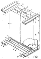
- FIG. 1 In the schematic illustration of a section of a holding device for printed circuit boards in shielded housings shown in FIG. 1, upper bars 1 and 2 and lower bars 3 and 4 are shown, from which the holding device is constructed.
- the spars are laterally attached to a frame or in a housing in a known manner. They are preferably designed as extruded profiles and have T-shaped grooves on both broad and narrow sides.
- T-shaped grooves 10 extending on the broad sides of the spars 1 to 4
- cross members can be fastened between two spars, which carry guide means.
- Fig. 1 two different embodiments of such cross members are shown.
- a guide plane which consists of a cross member 13 formed as a flat sheet metal part exists, which can be screwed by means of screws on the sheet metal strip 12 inserted in the T-shaped grooves with threaded holes.
- This cross member 13 carries as a guide means a plurality of parallel webs 14, which can be produced in a simple manner by punching a sheet metal strip and bending this sheet metal strip out of the surface of the cross member sheet.
- This embodiment has the advantage that only a few fasteners are required for fastening a large number of webs, furthermore that special gauges for maintaining defined distances between the guide means are dispensable for the assembly of the webs and that nevertheless when using modern numerically controlled punching machines without effort for special ones Tools cross beams can be produced in which the webs have different distances.
- a narrow sheet metal strip 15 is used as the crossmember, one longitudinal side of which is bent at right angles, so that an elongated sheet metal angle is formed, one leg of which forms the web 16 as a guide means.
- This sheet metal strip 15 can also be screwed on by means of screws on sheet metal strips 12 with threaded holes (threaded rails) or individual sliding nuts guided in the T-shaped grooves.
- This embodiment is also very simple and inexpensive to manufacture.
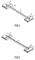
- FIG. 2 A further advantageous embodiment of a cross member with a web is shown in FIG. 2. It consists of a narrow support part 17, which is preferably made of plastic, and by means of corresponding latches on its underside into the T-shaped grooves 10 is snapped. On its upper side it carries a web 18 as a guide means.
- This embodiment like the aforementioned embodiment, has the advantage that the spacings of the cross members 15 from one another, depending on the width of the assemblies to be used, can be determined as desired when assembling a receiving device for a specific purpose.
- Fig. 3 shows a cross member 11, which has a groove as a guide means in a known manner, so that a circuit board with its edge can be guided therein.
- This cross member 11 with groove can also be snapped into the T-shaped grooves 10 of the spars 3 and 4 with corresponding locking means.
- the shield housing 5 for the circuit board 6 is formed from sheet metal.
- the front plate is attached to an angled plate attached to the front edge of the circuit board and is higher than the shield housing itself, so that it protrudes both above and below the outer dimensions of the shield housing. With these protruding sections of the front plate, it is screwed onto the front of the spars 2 or 4 in T-shaped grooves 9 threaded rails or sliding nuts.
- the distance between the upper spars 1 and 2 and the lower spars 3 and 4 is such that printed circuit boards of a certain size, for example in the so-called Euro card format, can be inserted if, as a guide, grooves-carrying cross members are attached to the spars in the usual way . Without changing the spacing of the spars from one another, the use of printed circuit boards of the same size in screen housings is possible if the guide means described above as a web are used.
- the shield housing 5 is against Grooves on the outside. As shown in the exemplary embodiment in FIG. 1, these consist of parallel impressions 8, between which the web 14 is guided. Parallel impressions 7 are also provided on opposite inner sides for guiding the printed circuit board 6 in the shield housing 5.
- Such impressions can be produced quickly and inexpensively in sheet metal material using numerically controlled punching and nibbling machines.
- the position of the grooves formed by the embossments can therefore be varied as desired, depending on the configuration of the printed circuit board or for each shield housing, without any special tool effort.
- Another advantage is that in the same receiving device cross members of conventional type with grooves and cross members with webs can be combined, so that both circuit boards in closed shield housings and unshielded circuit boards of the same size can be used in the same receiving device.
Abstract
Description
Die Erfindung betrifft eine Aufnahmevorrichtung mit Leiterplatten in Schirmgehäusen, die an zwei gegenüberliegenden Seitenwänden innen Nuten für die Aufnahme von wenigstens einer Leiterplatte und außen Führungsmittel aufweisen, welche mit entsprechenden Führungsmitteln in der Aufnahmevorrichtung zusammenwirken. Solche geschirmte Leiterplatten sind in der elektrischen Nachrichtentechnik gebräuchlich, die Aufnahmevorrichtungen können z.B. Gerätegehäuse oder Gestelle sein, in welchen eine Vielzahl solcher geschirmter Leiterplatten unterbringbar ist.The invention relates to a receiving device with printed circuit boards in shield housings which have grooves on the inside on two opposite side walls for receiving at least one printed circuit board and outside guide means which cooperate with corresponding guide means in the receiving device. Such shielded printed circuit boards are common in electrical communications technology, the receiving devices can e.g. Appliance housing or frames in which a large number of such shielded printed circuit boards can be accommodated.
Es ist bekannt, Aufnahmevorrichtungen zur Aufnahme von Leiterplatten an zwei gegenüberliegenden Innenseiten mit Führungsnuten zu versehen, in welche als bestückte Leiterplatten ausgebildete Baugruppen mit ihren Rändern eingeschoben werden können. Die Ränder der Leiterplatten bilden in diesem Fall an zwei einander gegenüberliegenden Seiten angeordnete Führungsmittel. Es ist ferner bekannt, solche Leiterplatten zur Abschirmung auf beiden Seiten mit Abschirmkappen aus Metall zu versehen, wobei die eine Abschirmkappe die Lötseite und die andere Abschirmkappe die Bauelementeseite abdeckt. Die Ränder der Leiterplatte bleiben dabei frei und sind auch in dieser geschirmten Ausführungsform als Führungsmittel verwendbar. Die Fertigung von zwei gesonderten Abschirmkappen und deren Anbringen auf jeweils einer Leiterplattenseite ist jedoch kostenaufwendig.It is known to provide receiving devices for receiving printed circuit boards on two opposite inner sides with guide grooves into which assemblies designed as assembled printed circuit boards can be inserted with their edges. In this case, the edges of the printed circuit boards form guide means arranged on two opposite sides. It is also known to provide such printed circuit boards for shielding on both sides with metal shielding caps, one shielding cap covering the solder side and the other shielding cap covering the component side. The edges of the circuit board remain free and can also be used as guide means in this shielded embodiment. However, the production of two separate shielding caps and their attachment to one side of the circuit board is costly.
Es ist aus DE-PS 27 47 894 ferner bekannt, zur Verbesserung der Abschirmung ein geschlossenes aus Metall gefer tigtes Gehäuse vorzusehen, welches an gegenüberliegenden Innenseiten Nuten aufweist, in welche die Leiterplatte eingeschoben werden kann. An zwei gegenüberliegenden Wänden der auf diese Weise gebildeten Flachbaugruppe befinden sich außen Führungsstege, welche in entsprechend geformten Nuten in einem Gestell oder in einem Aufnahmerahmen geführt sind. Werden in der gleichen Aufnahmevorrichtung sowohl ungeschirmte Leiterplatten wie auch geschirmte Flachbaugruppen vorstehend geschilderter Bauweise eingesetzt, so ergibt sich, daß bei einer gleichmäßigen Ausführung des Aufnahmerahmens die Leiterplatten unterschiedliche Abmessungen haben müssen, je nachdem, ob sie in einem Schirmgehäuse eingesetzt sind oder nicht. Bei der Leiterplattenherstellung haben sich jedoch bestimmte Normmaße herausgebildet, z.B. das sog."Europakartenformat". Entsprechend diesen Normmaßen sind die Abstände zwischen den Leiterplattenführungsebenen in den Gestellen und Aufnahmerahmen bemessen. Eine Verkleinerung der verfügbaren Leiterplattenoberfläche gegenüber dem Normmaß ist auch deshalb unerwünscht, weil hierdurch die Aufnahmekapazität der Leiterplatte eingeschränkt wird.It is also known from DE-PS 27 47 894, to improve the shielding a closed metal gefer Provided housing, which has grooves on opposite inner sides, into which the circuit board can be inserted. On two opposite walls of the flat module formed in this way there are guide webs on the outside, which are guided in correspondingly shaped grooves in a frame or in a receiving frame. If both unshielded printed circuit boards and shielded printed circuit boards of the construction described above are used in the same receiving device, it follows that with a uniform design of the receiving frame, the printed circuit boards must have different dimensions, depending on whether they are used in a shield housing or not. However, certain standard dimensions have emerged in the manufacture of printed circuit boards, for example the so-called "European card format". The distances between the PCB guide levels in the frames and mounting frames are dimensioned according to these standard dimensions. A reduction in the available printed circuit board surface area compared to the standard size is also undesirable because this limits the capacity of the printed circuit board.
Der Erfindung liegt die Aufgabe zugrunde, eine Einrichtung der eingangs Art so auszugestalten, daß ohne Abwandlung der Abmessungen der Gestelle oder Aufnahmerahmen Leiterplatten der sonst hierfür gebräuchlichen Größe in einem geschlossenen Schirmgehäuse einsetzbar sind.The invention is based on the object of designing a device of the type described in such a way that printed circuit boards of the size otherwise customary for this purpose can be used in a closed screen housing without modifying the dimensions of the frames or mounting frames.
Diese Aufgabe wird gemäß der Erfindung dadurch gelöst, daß die Führungsmittel in der Aufnahmevorrichtung Stege und die Führungsmittel am Schirmgehäuse Nuten sind. Eine Weiterbildung der Erfindung wird darin gesehen, daß das Schirmgehäuse aus Blech besteht und die Nuten durch Einprägungen gebildet sind. Ein derart ausgebildetes Schirmgehäuse ist besonders kostengünstig zu fertigen, da für die Nuten keine gesonderten Teile erforderlich sind.This object is achieved according to the invention in that the guide means in the receiving device are webs and the guide means on the screen housing are grooves. A further development of the invention is seen in that the shield housing consists of sheet metal and the grooves are formed by embossing. Such a shield housing is particularly inexpensive to manufacture because for the grooves no separate parts are required.
Eine weitere Verbesserung besteht darin, daß die Aufnahmevorrichtung aus Blech geformte Querträger mit mehreren parallelen Stegen aufweist, wobei die Stege aus der Blechoberfläche freigestanzte und rechtwinklig umgebogene Blechstreifen sind.A further improvement consists in the fact that the holding device has cross members formed from sheet metal with a plurality of parallel webs, the webs being sheet metal strips which are punched out of the sheet metal surface and bent at right angles.
Im folgenden soll die Erfindung anhand eines in den Fig. 1 bis 3 dargestellten Ausführungsbeispieles näher beschrieben und erläutert werden.The invention will be described and explained in more detail below with reference to an exemplary embodiment shown in FIGS. 1 to 3.
Es zeigt in schematischer Darstellung:
- Fig. 1 eine Schrägansicht eines Ausschnittes einer Aufnahmevorrichtung mit einer eingesetzten geschirmten Leiterplatte,
- Fig. 2 einen Querträger mit Führungssteg,
- Fig. 3 einen Querträger mit Führungsnut,
- 1 is an oblique view of a section of a receiving device with an inserted shielded circuit board,
- 2 a cross member with a guide bar,
- 3 shows a cross member with a guide groove,
In der in Fig. 1 gezeigten schematischen Darstellung eines Ausschnittes einer Aufnahmevorrichtung für Leiterplatten in Schirmgehäusen sind obere Holme 1 und 2 sowie untere Holme 3 und 4 gezeigt, aus denen die Aufnahmevorrichtung aufgebaut ist. Die Holme sind in bekannter Weise seitlich an einem Rahmengestell oder in einem Gehäuse befestigt. Sie sind vorzugsweise als Strangpressprofile ausgebildet und tragen sowohl an Breit- wie an Schmalseiten T-förmige Nuten. In den an den Breitseiten der Holme 1 bis 4 verlaufenden T-förmigen Nuten 10 sind zwischen je zwei Holmen Querträger befestigbar, welche Führungsmittel tragen. In Fig. 1 sind zwei verschiedene Ausführungsformen solcher Querträger dargestellt. Als erste Ausführungsform ist eine Führungsebene vorgesehen, die aus einem in als flaches Blechteil ausgebildeten Querträger 13 besteht, welcher mittels Schrauben an in den T-förmigen Nuten eingesetzen Blechstreifen 12 mit Gewindelöchern festschraubbar ist. Anstelle eines Blechstreifens mit Gewindelöchern sind auch einzelne Schiebemuttern verwendbar. Dieser Querträger 13 trägt als Führungsmittel mehrere parallele Stege 14, welche in einfacher Weise durch Freistanzen eines Blechstreifen und Umbiegen dieses Blechstreifens aus der Oberfläche des Querträgerbleches hergestellt werden können. Diese Ausführungsform hat den Vorteil, daß zur Befestigung einer Vielzahl von Stegen nur wenig Befestigungsmittel notwendig sind, daß ferner bei der Montage der Stege besondere Lehren zur Einhaltung definierter Abstände der Führungsmittel voneinander entbehrlich sind und daß dennoch beim Einsatz moderner numerisch gesteuerter Stanzmaschinen ohne Aufwand für besondere Werkzeuge Querträger herstellbar sind, bei denen die Stege unterschiedliche Abstände aufweisen.In the schematic illustration of a section of a holding device for printed circuit boards in shielded housings shown in FIG. 1,
Eine andere Ausführungsform der Querträger besteht darin, daß als Querträger ein schmaler Blechstreifen 15 verwendet ist, dessen eine Längsseite rechtwinklig umgebogen ist, so daß ein langgestreckter Blechwinkel entsteht, dessen einer Schenkel den Steg 16 als Führungsmittel bildet. Dieser Blechstreifen 15 ist ebenfalls mittels Schrauben an in den T-förmigen Nuten geführten Blechstreifen 12 mit Gewindelöchern (Gewindeschienen) oder einzelnen Schiebemuttern anschraubbar. Auch diese Ausführungsform ist sehr einfach und kostengünstig herstellbar.Another embodiment of the crossmember is that a narrow
Eine weitere vorteilhafte Ausführungsform eines Querträgers mit Steg ist in Fig. 2 gezeigt. Sie besteht aus einem schmalen Trägerteil 17, welches vorzugsweise aus Kunststoff gefertigt ist und mittels entsprechenden Rastnasen an seiner Unterseite in die T-förmigen Nuten 10 einschnappbar ist. An seiner Oberseite trägt es als Führungsmittel einen Steg 18. Diese Ausführungsform hat ebenso wie die vorerwähnte Ausführungsform den Vorteil, daß die Abstände der Querträger 15 voneinander je nach der Breite der einzusetzenden Baugruppen beim Zusammenstellen einer Aufnahmevorrichtung für einen bestimmten Zweck beliebig bestimmbar sind.A further advantageous embodiment of a cross member with a web is shown in FIG. 2. It consists of a
Fig. 3 zeigt ein Querträger 11, welcher in bekannter Weise als Führungsmittel eine Nut aufweist, so daß eine Leiterplatte mit ihrer Kante darin führbar ist. Dieser Querträger 11 mit Nut ist ebenfalls mit entsprechenden Rastmitteln in den T-förmigen Nuten 10 der Holme 3 und 4 einschnappbar.Fig. 3 shows a
Das Schirmgehäuse 5 für die Leiterplatte 6 ist aus Blech geformt. Die Frontplatte ist an einem an der Vorderkante der Leiterplatte angebrachten Winkelblech befestigt und ist höher als das Schirmgehäuse selbst, so daß sie sowohl oben als auch unten über die Außenabmessungen des Schirmgehäuses hinausragt. Mit diesen überragenden Abschnitten der Frontplatte ist diese an der Vorderseite der Holme 2 bzw. 4 in T-förmigen Nuten 9 gehaltenen Gewindeschienen oder Schiebemuttern angeschraubt.The
Der Abstand zwischen den oberen Holmen 1 und 2 und den unteren Holmen 3 und 4 ist so bemessen, daß Leiterplatten in einer bestimmten Größe, z.B. im sogenannten Europakartenformat, eingeschoben werden können, wenn als Führungsmittel in üblicher Weise Nuten tragende Querträger an den Holmen befestigt sind. Ohne Veränderung des Abstandes der Holme voneinander ist der Einsatz von Leiterplatten der gleichen Größe in Schirmgehäusen möglich, wenn die vorstehend beschriebenen als Steg ausgebildeteten Führungsmittel verwendet sind. Das Schirmgehäuse 5 ist an gegen überliegenden Außenseiten mit Nuten versehen. Diese bestehen, wie im Ausführungsbeispiel Fig. 1 gezeigt, aus parallelen Einprägungen 8, zwischen denen der Steg 14 geführt ist. Zur Führung der Leiterplatte 6 im Schirmgehäuse 5 sind an gegenüberliegenden Innenseiten ebenfalls parallele Einprägungen 7 vorgesehen. Solche Einprägungen lassen sich in Blechmaterial mittels numerisch gesteuerter Stanz- und Nibbelmaschinen mit hoher Genauigkeit schnell und kostengünstig erzeugen. Die Lage der durch die Einprägungen gebildeteten Nuten kann daher abhängig von der Bestückung der Leiterplatte bzw. für jedes Schirmgehäuse gesondert ohne besonderen Aufwand an Werkzeug beliebig variiert werden.The distance between the
Infolge der Anordnung von nach außen weisenden Einprägungen zur Führung des Schirmgehäuses sowie von nach innen weisenden Einprägungen zur Führung der Leiterplatte im Schirmgehäuse ist der Unterschied der Kantenabmessungen zwischen ungeschirmter Leiterplatte und Schirmgehäuse mit Leiterplatte außerordentlich gering.As a result of the arrangement of outward-facing impressions for guiding the shield housing and of inward-facing impressions for guiding the printed circuit board in the shield housing, the difference in edge dimensions between unshielded printed circuit board and shielded housing with printed circuit board is extremely small.
Ein weiterer Vorteil besteht darin, daß in der gleichen Aufnahmevorrichtung Querträger herkömmlicher Art mit Nuten und Querträger mit Stegen kombinierbar sind, so daß in der gleichen Aufnahmevorrichtung sowohl Leiterplatten in geschlossenen Schirmgehäusen als auch ungeschirmte Leiterplatten gleicher Größe einsetzbar sind.Another advantage is that in the same receiving device cross members of conventional type with grooves and cross members with webs can be combined, so that both circuit boards in closed shield housings and unshielded circuit boards of the same size can be used in the same receiving device.
Claims (5)
Applications Claiming Priority (2)
| Application Number | Priority Date | Filing Date | Title |
|---|---|---|---|
| DE19873735456 DE3735456A1 (en) | 1987-10-20 | 1987-10-20 | RECEIVER WITH SHIELDED CIRCUIT BOARDS |
| DE3735456 | 1987-10-20 |
Publications (2)
| Publication Number | Publication Date |
|---|---|
| EP0313131A2 true EP0313131A2 (en) | 1989-04-26 |
| EP0313131A3 EP0313131A3 (en) | 1989-12-20 |
Family
ID=6338697
Family Applications (1)
| Application Number | Title | Priority Date | Filing Date |
|---|---|---|---|
| EP88202193A Withdrawn EP0313131A3 (en) | 1987-10-20 | 1988-10-04 | Housing device with shielded boards |
Country Status (4)
| Country | Link |
|---|---|
| US (1) | US5008778A (en) |
| EP (1) | EP0313131A3 (en) |
| JP (1) | JPH01135098A (en) |
| DE (1) | DE3735456A1 (en) |
Families Citing this family (11)
| Publication number | Priority date | Publication date | Assignee | Title |
|---|---|---|---|---|
| DE3928461C3 (en) * | 1989-08-29 | 1997-10-16 | Aeg Intermas Gmbh | Subrack |
| DE4105548C1 (en) * | 1991-02-22 | 1992-06-25 | Schroff Gmbh, 7541 Straubenhardt, De | |
| US5642264A (en) * | 1991-04-01 | 1997-06-24 | E-Systems, Inc. | Apparatus for supporting circuit cards in slot locations |
| US5172306A (en) * | 1991-04-01 | 1992-12-15 | E-Systems, Inc. | Adaptive card mounting system |
| US5826201A (en) * | 1992-11-25 | 1998-10-20 | Asterion, Inc. | Antenna microwave shield for cellular telephone |
| US5641301A (en) * | 1995-03-31 | 1997-06-24 | Unisys Corporation | Lead-in guide for printed circuit boards |
| DE19912858A1 (en) * | 1999-03-22 | 2000-10-19 | Tyco Electronics Logistics Ag | Connectable printed circuit boards for e.g. computer card has guide elements for other elements next to computer cards |
| US6958563B2 (en) * | 2003-01-16 | 2005-10-25 | Energy Conversion Systems Holdings, Llc | Riser commutators |
| EP1578146A1 (en) * | 2004-03-18 | 2005-09-21 | 3M Innovative Properties Company | Carrier of a distribution point in the field of telecommunications |
| US20070127225A1 (en) * | 2005-12-05 | 2007-06-07 | Slaton David S | Method and system for mounting circuit boards |
| USD796313S1 (en) * | 2015-05-19 | 2017-09-05 | Triangle Brass Manufacturing Company, Inc. | Door push plate |
Citations (3)
| Publication number | Priority date | Publication date | Assignee | Title |
|---|---|---|---|---|
| FR1367798A (en) * | 1962-07-20 | 1964-07-24 | Sperry Rand Corp | Connector assembly for printed circuit boards |
| DE2747894A1 (en) * | 1977-10-26 | 1979-05-03 | Tekade Felten & Guilleaume | Screen for printed circuit board - has metal housing fitting tightly over lip of metal plate that holds coaxial connectors |
| DE3209205A1 (en) * | 1982-03-13 | 1983-09-22 | Licentia Patent-Verwaltungs-Gmbh, 6000 Frankfurt | Guide holder for electronic assemblies |
Family Cites Families (4)
| Publication number | Priority date | Publication date | Assignee | Title |
|---|---|---|---|---|
| US3289047A (en) * | 1964-10-16 | 1966-11-29 | Sylvania Electric Prod | Housing for a mechanically alterable memory system |
| US3878438A (en) * | 1973-09-28 | 1975-04-15 | William Jacobs A K A Calmark | Printed circuit card guide |
| US4386388A (en) * | 1981-09-04 | 1983-05-31 | Northern Telecom Limited | Printed circuit board assembly |
| US4533977A (en) * | 1984-05-17 | 1985-08-06 | Gte Communication Systems Corporation | Printed wiring board assembly employing track engaging runners |
-
1987
- 1987-10-20 DE DE19873735456 patent/DE3735456A1/en not_active Withdrawn
-
1988
- 1988-10-04 EP EP88202193A patent/EP0313131A3/en not_active Withdrawn
- 1988-10-17 US US07/258,405 patent/US5008778A/en not_active Expired - Fee Related
- 1988-10-18 JP JP63260686A patent/JPH01135098A/en active Pending
Patent Citations (3)
| Publication number | Priority date | Publication date | Assignee | Title |
|---|---|---|---|---|
| FR1367798A (en) * | 1962-07-20 | 1964-07-24 | Sperry Rand Corp | Connector assembly for printed circuit boards |
| DE2747894A1 (en) * | 1977-10-26 | 1979-05-03 | Tekade Felten & Guilleaume | Screen for printed circuit board - has metal housing fitting tightly over lip of metal plate that holds coaxial connectors |
| DE3209205A1 (en) * | 1982-03-13 | 1983-09-22 | Licentia Patent-Verwaltungs-Gmbh, 6000 Frankfurt | Guide holder for electronic assemblies |
Non-Patent Citations (1)
| Title |
|---|
| PRODUCT ENGINEERING. vol. 34, no. 11, 27 Mai 1963, NEW YORK US Seiten 36 - 37; SCHUSTER: "8 printed circuit guides." * |
Also Published As
| Publication number | Publication date |
|---|---|
| EP0313131A3 (en) | 1989-12-20 |
| US5008778A (en) | 1991-04-16 |
| DE3735456A1 (en) | 1989-05-03 |
| JPH01135098A (en) | 1989-05-26 |
Similar Documents
| Publication | Publication Date | Title |
|---|---|---|
| EP0313131A2 (en) | Housing device with shielded boards | |
| DE2833043A1 (en) | Housing for telecommunications circuit boards - is extruded tubular body with guides on inner surface for boards and slots on outer surface for fastening elements | |
| EP0283973B1 (en) | Device for mounting housings in the openings of a switchboard or a matrix panel | |
| WO2022053379A1 (en) | Housing for an electronic circuit which is arranged on a printed circuit board | |
| EP0014391A1 (en) | Module-module support system for electronic circuits | |
| EP0447942A1 (en) | EMI impermeable multiple plug for interconnection of metallic board elements | |
| DE3634462C2 (en) | ||
| DE1490515B1 (en) | HOLDING DEVICE FOR CIRCUIT COMPONENTS | |
| DE2714562B2 (en) | Subrack | |
| DE3023085C2 (en) | Method for pressing a guide carrier with protruding guide elements for cards or printed circuits for electronics | |
| DE1182316B (en) | Support frame for insertion in frames or housings in communications engineering and / or electronics | |
| DE3417451A1 (en) | Plug-in housing | |
| EP2831970B1 (en) | System module for electroinstallation technology for buildings and door communication technology | |
| EP0596349A2 (en) | Electric rack | |
| DE19518220B4 (en) | Extraction device for a telecommunication device frame | |
| DE3624682C2 (en) | ||
| DE3231886C2 (en) | Front panel for an electronic assembly and method for producing this front panel | |
| DE2629207C3 (en) | Housings for electrical devices made from extruded profile parts | |
| DE3521014C2 (en) | ||
| EP0217162B1 (en) | Device for the fixation of guide rails for electrical interior constructions by a standard grid rail | |
| DE3624756C2 (en) | ||
| DE3112642C2 (en) | Frame for slide-in electrical assemblies | |
| DE2611511A1 (en) | CARRYING GRID FOR INSTRUMENT HOUSING | |
| DE2503199C3 (en) | Device carrier plate | |
| EP0906717A1 (en) | Subassembly rack with pluggable subassemblies comprising front plates that can be centred |
Legal Events
| Date | Code | Title | Description |
|---|---|---|---|
| PUAI | Public reference made under article 153(3) epc to a published international application that has entered the european phase |
Free format text: ORIGINAL CODE: 0009012 |
|
| AK | Designated contracting states |
Kind code of ref document: A2 Designated state(s): DE FR GB IT |
|
| PUAL | Search report despatched |
Free format text: ORIGINAL CODE: 0009013 |
|
| AK | Designated contracting states |
Kind code of ref document: A3 Designated state(s): DE FR GB IT |
|
| 17P | Request for examination filed |
Effective date: 19900614 |
|
| 17Q | First examination report despatched |
Effective date: 19920624 |
|
| STAA | Information on the status of an ep patent application or granted ep patent |
Free format text: STATUS: THE APPLICATION HAS BEEN WITHDRAWN |
|
| 18W | Application withdrawn |
Withdrawal date: 19921105 |